
TPT420 - Measuring equipment Megger - Free user manual and instructions
Find the device manual for free TPT420 Megger in PDF.
| Product Type | Bipolar voltage tester |
| Brand | Megger |
| Model | TPT420 |
| Category | Measuring equipment |
| Dimensions | 67 (W) x 205 (H) x 19 mm (D) |
| Weight | 180 g |
| Power supply | 2 AAA 1.5 V batteries (IEC R03) |
| AC voltage range | 12 to 1000 V AC (40-400 Hz) |
| DC voltage range | 12 to 1500 V DC |
| LED voltages | 12, 24, 50, 120, 230, 400, 690, 1000 V |
| Continuity test | 0 to 500 kΩ |
| Phase rotation test | 120 to 400 V phase-earth AC 50/60 Hz |
| Single-pole test | 100 to 1000 V AC 50/60 Hz |
| Display | LCD + LED |
| Protection | IP64 |
| Overvoltage category | CAT IV 1000 V |
| Safety standard | EN61243-3 |
| Operating temperature | -5 to 40 °C |
| Storage temperature | -20 to 70 °C |
| Relative humidity | 85 % max |
| Max altitude | 2000 m |
| Peak current | < 3.5 mA |
| Consumption | Approx. 80 mA |
| Additional functions | LED flashlight, vibrator, polarity detection |
| Maintenance | Clean with a dry cloth, replace batteries if needed |
| Safety | Do not use in humid environment, check batteries before use, respect CAT IV |
Frequently Asked Questions - TPT420 Megger
User questions about TPT420 Megger
0 question about this device. Answer the ones you know or ask your own.
Ask a new question about this device
Download the instructions for your Measuring equipment in PDF format for free! Find your manual TPT420 - Megger and take your electronic device back in hand. On this page are published all the documents necessary for the use of your device. TPT420 by Megger.
USER MANUAL TPT420 Megger
Two pole voltage tester
User guide
Mode d'emploi
Bedienungsanleitung
Guía de usuario
Handleiding
Guida per l'utente
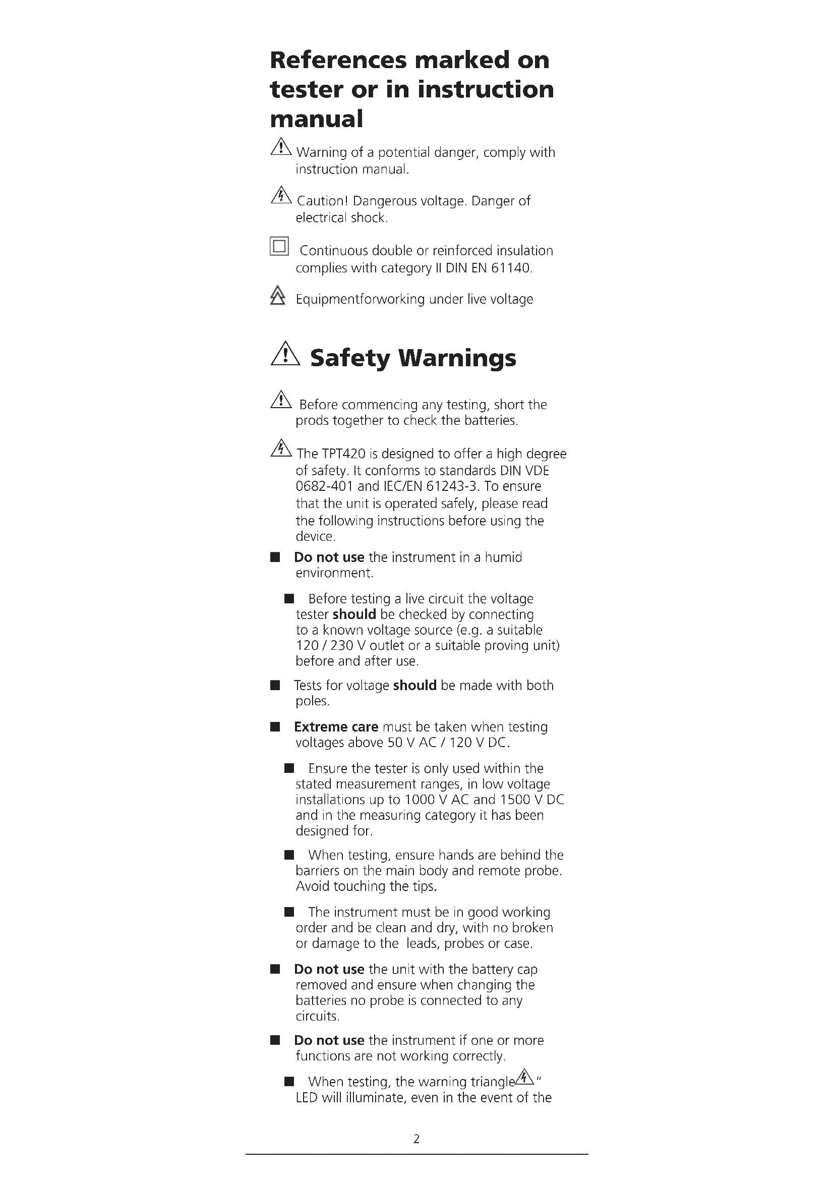
References marked on tester or in instruction manual
⚠ Warning of a potential danger, comply with instruction manual.
Caution! Dangerous voltage. Danger of electrical shock.
Continuous double or reinforced insulation complies with category II DIN EN 61140.
Equipmentforworking under live voltage
⚠ Safety Warnings
⚠️ Before commencing any testing, short the prods together to check the batteries.
The TPT420 is designed to offer a high degree of safety. It conforms to standards DIN VDE 0682-401 and IEC/EN 61243-3. To ensure that the unit is operated safely, please read the following instructions before using the device.
■ Do not use the instrument in a humid environment.
■ Before testing a live circuit the voltage tester should be checked by connecting to a known voltage source (e.g. a suitable 120 / 230 V outlet or a suitable proving unit) before and after use.
■ Tests for voltage should be made with both poles.
■ Extreme care must be taken when testing voltages above 50 V AC / 120 V DC.
■ Ensure the tester is only used within the stated measurement ranges, in low voltage installations up to 1000 V AC and 1500 V DC and in the measuring category it has been designed for.
■ When testing, ensure hands are behind the barriers on the main body and remote probe. Avoid touching the tips.
■ The instrument must be in good working order and be clean and dry, with no broken or damage to the leads, probes or case.
- Do not use the unit with the battery cap removed and ensure when changing the batteries no probe is connected to any circuits.
■ Do not use the instrument if one or more functions are not working correctly.
■ When testing, the warning triangle 4 " LED will illuminate, even in the event of the
batteries being exhausted. This must not be used for measuring purposes.
■ The audible indication may not be heard in noisy environments.
■ Remove the batteries if the tester is not to be used for a long period of time.
■ The voltage tester must not be used with exhausted or leaked batteries. Danger of electric shock!
SAFETY ADVICE
A voltage detector of relatively low internal impedance, compared to the reference value of 100 kΩ, will not indicate all interference voltages or noise having an original voltage value above the ELV level. When in contact with the parts to be tested, the voltage detector may reduce the interference voltage or noise by discharging temporarily to a level below the ELV, but it will go back to the original value when the voltage detector is removed.
A voltage detector declaring two values of internal impedance has passed a performance test of managing interference voltages or noise and is (within technical limits) able to distinguish operating voltage from interference voltage and has a means to directly or indirectly indicate which type of voltage is present.
- When there is no indication of "voltage present", it is still recommended to earth equipment before commencing work.
A voltage detector of relatively high internal impedance, compared to the reference value of 100 kΩ, may not permit to clearly indicate the absence of operating voltage in case of presence of interference voltage.
When the indication "voltage present" appears on a part that is expected to be isolated from the installation, it is highly recommended confirming by another means (e.g. use of an adequate voltage detector, visual check of the disconnecting point of the electric circuit, etc.) that there is no operating voltage on the part to be tested and to ensure that the voltage indicated by the voltage detector is an interference voltage.
A voltage detector declaring two values of internal impedance has passed a performance test of managing interference voltages and is (within technical limits) able to distinguish operating voltage from interference voltage and has a means to directly or indirectly indicate which type of voltage is present.
General point: Voltage tests have priority on the TPT420. That means that if life voltage is detected this will be indicated. If no voltage is detected at the probe tip (<6 V), the device is in continuity mode.
Introduction
The Megger TPT420 voltage tester provides electricians and electrical engineers with voltage indication and has additional functions / features that makes the instrument more versatile.
The TPT420 features both LCD and LED displays that provide AC and DC voltage measurement from 12 to 1000 V AC and 1500 V DC and in addition, a continuity function ranging from 0 to 500 kΩ. Continuity and voltage measurements are accompanied by an acoustic sounder.
A bright LED torch feature allows safe working in poorly lit environments.
When conducting a test between phase and earth on a circuit protected by an RCD, RCBO and Safety Breaker, the TPT420 will not trip these devices.
The phase rotation indication function is simplified which avoids the crossing of the test probes adopted by some 2 pole testers.
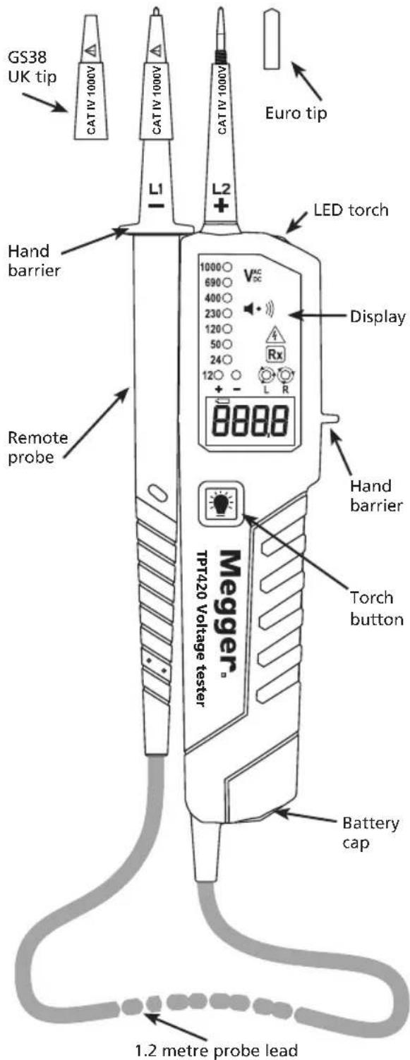
With safety in mind, the TPT420 is CAT IV 1000 V with an IP64 rated housing that provides an easy and comfortable grip. GS38 shrouds are provided as standard.
The unit has a feature that will warn the operator of dangerous test voltages even when the batteries have become exhausted.
Please note: To comply with GS38 (minimum exposed tip) the metal caps on each prod must be unscrewed and replaced with the supplied plastic tip shrouds.
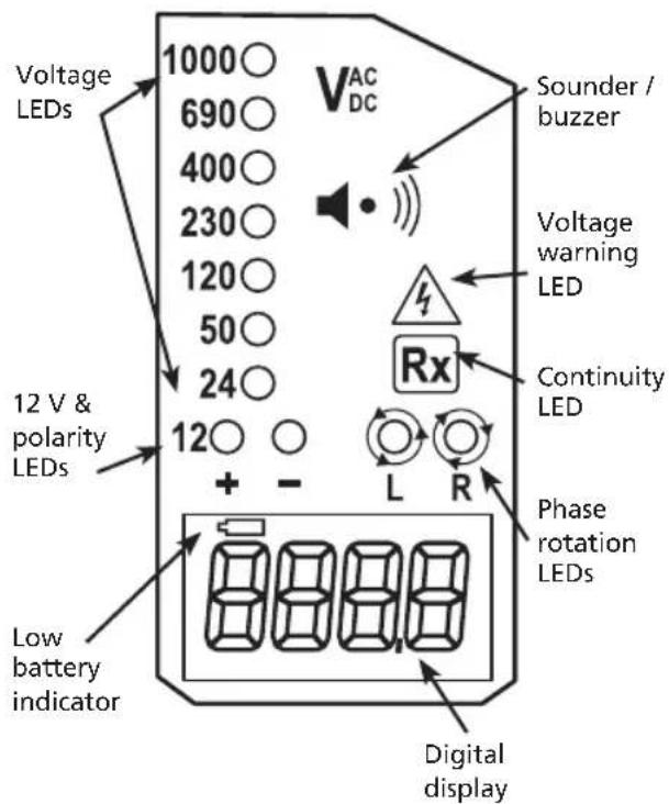
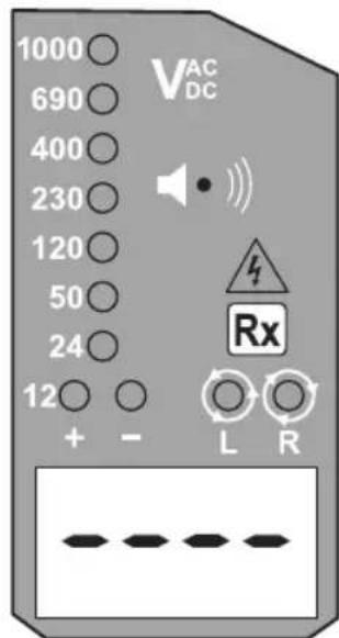
TPT420 Display
TPT420 Feature
Operating instructions
Auto-power-on / switching on
The tester switches on when it detects continuity, an AC or DC voltage above approx. 10 V or a live phase on L2 (single pole test). It can also be switched on with the torch light button.
Auto-power off
The tester is automatically powered off after 5 sec when there is no signal detected by the probes. The torch light switches off after approx. 10 sec.
Self test
Before commencing any measurements with the TPT420 a self test should be made. Short the probes tips together; the continuity LED will illuminate and a continuous audible tone will be heard. This procedure checks the batteries have sufficient power to operate the voltage tester correctly.
CAUTION: This test does not indicate the tester is capable of indicating correct supply voltage; a known live supply or a dedicated proving unit should be utilised to check the voltage measuring capability of the unit before and after testing.
If only the voltage warning LED illuminates (>50 VAC / >120 VDC) and the LCD display is blank then check the batteries.
(This feature must not be used as a means of continuing voltage indications.)
If the low battery indicator appears in the LCD window then change the batteries.
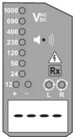
Continuity test
Ensure the circuit under test is not energised. Connect both test probes to the circuit. The continuity LED illuminates and buzzer sounds continuously to indicate continuity < 500 kΩ. Note: No continuity measurement is available on the LCD display.
Diode test
Connect the L1 - probe to the anode of the diode and the L2 + probe to the cathode. The continuity LED will illuminate and the buzzer will sound. Reversing the connections, the continuity LED will not illuminate and no sound will be present.
AC/DC Voltage test
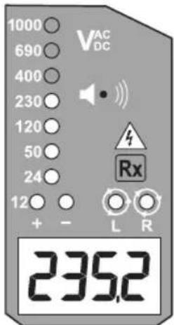
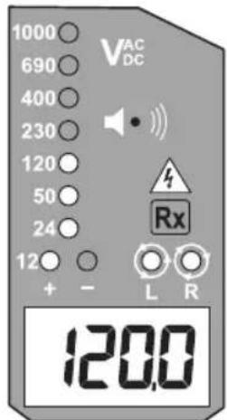
Connect both probes to the circuit under test. The voltage is indicated by LEDs and the LCD display.
The buzzer sounds when a threshold voltage of approximately 38 VAC or approximately 100 VDC is exceeded.
Voltage polarity is indicated in following manner.
AC: Both + and - 12 V LEDs are on.
+DC: +12 V LED is on.
-DC: -12 V LED is on.
When the L2 probe + is the positive (negative) potential, the Polarity indication LED indicates "+DC" ("-DC").
During a voltage test, L or R LEDs may illuminate. For voltages over 1000 V AC and 1500 V DC the LCD will display 'OL'.
Single-pole phase test
Hold the tester securely in your hand. Connect the "L2+" probe to the object under test.
Voltage warning LED lights up and buzzer sounds when a voltage of approximately 100 V AC or more exists in the object under test.
Function of this test may not be fully achieved if the insulation condition / grounding conditions of user or of the equipment under test are not good enough.
Note: Verification of live-circuits should not be dependent on a Single-pole phase test only.
Phase rotation test
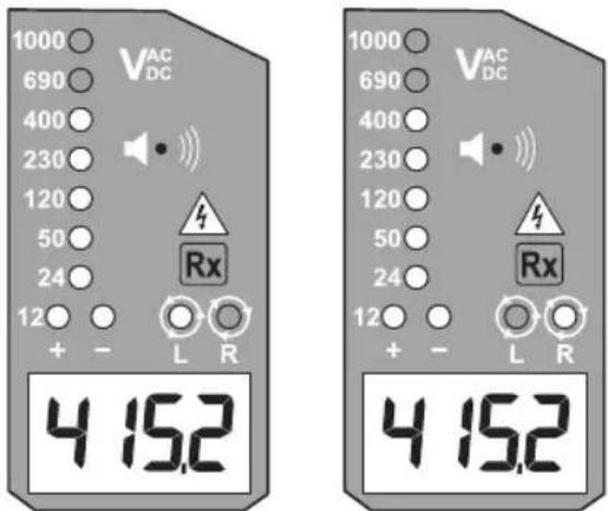
L LED and R LED's for the Phase rotation test may operate on various wiring systems, but an effective test result can only be obtained on three-phase 4-wire systems.
Hold the tester and remote probe firmly in each hand, ensuring hands are behind the hand barriers, and connect the probes to the object under test, each probe to one of the phases that should be tested. Phase-to-phase voltage is indicated by voltage LEDs and LCD display.
R LED lights up for Right rotary field. (L1, L2, L3)
L LED lights up for Left rotary field. (L1, L3, L2)
Measurement principle: The instrument detects the phase rising order referencing the user as earth. The function of this test may not be fully achieved if the insulation condition/ grounding conditions of user or of the equipment under test are not good enough.
Torch light
Pressing the torch light button will turn on the light and after approximately 10s it will turn itself off.
Battery Replacement
Remove the probes from any testing point, when opening the battery cap. Batteries are exhausted when the "continuity/self" test with both test probes connected cannot be achieved anymore. A battery symbol in the LCD display indicates low battery.
Follow the procedure below and replace batteries with new ones (type AAA / IEC R03 1.5 V).
Unscrew the battery cap, e.g. with a screwdriver. Pull out the battery cap and replace the batteries. Insert new batteries according to the engraving on the battery cap and re-assemble battery cap. Confirm that the battery cap is properly locked prior to measurements.
CE - Conformity symbol, the instrument complies with the valid directives. It complies with the EMV Directive (2014/30/EU), Standard EN 61326-1 are fulfilled. It also complies with the Low Voltage Directive (2014/35/EU), Standard EN61243-3 is fulfilled.
CAT IV - Measurement category IV: Equipment connected between the origin of the low-voltage mains supply outside the building and the consumer unit.
CAT III - Measurement category III: Equipment connected between the consumer unit and the electrical outlets.
CAT II - Measurement category II: Equipment connected between the electrical outlets and the user's equipment.

WEEE Directive
The crossed out wheeled bin symbol on the instrument and on the batteries is a reminder not to dispose of them with general waste at the end of their life.
Megger is registered in the UK as a Producer of Electrical and Electronic equipment. The registration no is; WEE/DJ2235XR.
Users of Megger products in the UK may dispose of them at the end of their useful life by contacting B2B Compliance at www.b2bcompliance.org.uk or by telephone on 01691676124.
Users of Megger products in other parts of the EU should contact their local Megger company or distributor.
Battery Disposal
Batteries in this product are classified as Portable Batteries under the Batteries Directive. Please contact Megger Ltd for instructions on the safe disposal of these batteries.
For disposal of batteries in other parts of the EU contact your local distributor.
Megger is registered in the UK as a producer of batteries.
The registration number is BPRN01235.
For Further information see www.megger.com
Specifications
Voltage range: 12...1000 V AC 1500 V DC (40...400 Hz), DC(±)
LED Nominal voltage: 12 / 24 / 50 / 120 / 230 / 400 / 690 / 1000 V, AC (40...400 Hz), DC(±)
LED tolerances: According to EN61243-3
Voltage warning
indication LED <50 VAC, <120 VDC
Response time: < 1s at 100% of each nominal voltage
LCD Range: 12...1000 V AC 1500 V DC (40...400 Hz), DC(±)
LCD Resolution: 0.1 V
LCD Accuracy: ±3%±5dgt
LCD Over range
indication: "OL"
Peak current: Is<3.5 mA (at 1000 V)
Measurement Duty: 30 s ON (operation time), 240 s OFF (recovery time)
Internal battery
consumption: Approx. 80 mA
Single-pole phase
test voltage range: 100...1000 V AC (50/60 Hz)
Phase rotation test: 120...400 V earth-to-phase, AC 50/60 Hz
Continuity test: 0...500 kΩ + 50%
Battery: 2 x 1,5V AAA, IEC R03
Temperature: -5...40 °C operation; -20...70 °C storage, No condensation
Humidity: Max 85 % RH
Altitude: Up to 2000 m
Over voltage: CAT IV / 1000 V
Safety Standard: EN61243-3
Pollution degree: 2
Protection: IP64
Dimensions: 67(W)×205(L)×19mm(D)
Weight: 180 g
Repair and warranty
The instrument contains static sensitive devices, and care must be taken in handling the printed circuit board. If an instrument's protection has been impaired it should not be used, but sent for repair by suitably trained and qualified personnel. The protection is likely to be impaired if for example; it shows visible damage; fails to perform the intended measurements; has been subjected to prolonged storage under unfavourable conditions, or has been subjected to severe transport stresses.
Note: Any unauthorised prior repair or adjustment will automatically invalidate the warranty.
Instrument repair and spare parts
For service requirements for Megger instruments contact:
Megger Limited
Dover, Kent CT17 9EN
England
Tel: +44 (0) 1304 502 243
Fax: +44 (0) 1304 207 342
Megger
Valley Forge Corporate Centre
2621 Van Buren Avenue
Norristown, PA 19403 USA
Tel: +1 610 676 8579
Fax: +1 610 676 8625
or an approved repair company.
Returning an Instrument for Repair
If it is necessary to return an instrument for repair, a Returns Authorisation number must first be obtained by contacting one of the addresses shown. You will be asked to provide key information, such as the instrument serial number and fault reported when the number is issued. This will enable the Service Department to prepare in advance for the receipt of your instrument, and to provide the best possible service to you.
The Returns Authorisation number should be clearly marked on the outside of the product packaging, and on any related correspondence. The instrument should be sent, freight paid to the appropriate address. If appropriate a copies of the original purchase invoice and of the packing note, should be sent simultaneously by airmail to expedite clearance through customs.
For instruments requiring repair outside the warranty period a repair estimate will be submitted to the sender, if required, before work on the instrument commences.
Declaration of Conformity
Hereby, Megger Instruments Limited declares that radio equipment manufactured by Megger Instruments Limited described in this user guide is in compliance with Directive 2014/53/EU.
Other equipment manufactured by Megger Instruments Limited described in this user guide is in compliance with Directives 2014/30/EU and 2014/35/EU where they apply.
The full text of Megger Instruments EU declarations of conformity are available at the following internet address: megger.com/eu-dofc.
Megger.
TPT420
Valley Forge Corporate Centre
2621 Van Buren Avenue
Valley Forge Corporate Centre
2621 Van Buren Avenue
Norristown, PA 19403 USA
Tel: +1 610 676 8579
Fax: +1 610 676 8625
Valley Forge Corporate Centre
2621 Van Buren Avenue
Norristown, PA 19403 USA
Tel: +1 610 676 8579
Fax: +1 610 676 8625
Valley Forge Corporate Centre
2621 Van Buren Avenue
Norristown, PA 19403 USA
Tel.: +1 610 676 8579
Faks: +1 610 676 8625
Valley Forge Corporate Centre
2621 Van Buren Avenue
Norristown, PA 19403 USA
Tel: +1 610 676 8579
Faks: +1 610 676 8625
Archcliffe Road, Dover
Kent CT17 9EN England
T +44 (0)1 304 502101
F +44 (0)1 304 207342
E uksales@megger.com
Megger
Z.A. Du Buisson de la Couldre
23 rue Eugène Henaff
78190 TRAPPES France
Unit 26 9 Hudson Avenue
Castle Hill
Sydney NSW 2125 Australia
T +61 (0)2 9659 2005
F +61 (0)2 9659 2201
E ausales@megger.com
Megger Limited
Unit 106-550 Alden Road
Markham
Ontario L3R6A8
Canada
T +1 416 298 9688 (Canada only)
T +1 416 298 6770
F +1 416 298 0848
E casales@megger.com
Megger products are distributed in 146 countries worldwide.
The company reserves the right to change the specification or design without prior notice.
Megger is a registered trademark
TPT420_ug_en-fr-de-es-nl-it-pl-tr_V03b
www.megger.com
- Two pole voltage tester
- References marked on tester or in instruction manual
- ⚠ Safety Warnings
- SAFETY ADVICE
- Introduction
- TPT420 Display
- TPT420 Feature
- Operating instructions
- Auto-power-on / switching on
- Auto-power off
- Self test
- If only the voltage warning LED illuminates (>50 VAC / >120 VDC) and the LCD display is blank then check the batteries.
- Continuity test
- Diode test
- AC/DC Voltage test
- Voltage polarity is indicated in following manner.
- Single-pole phase test
- Phase rotation test
- R LED lights up for Right rotary field. (L1, L2, L3)
- L LED lights up for Left rotary field. (L1, L3, L2)
- Torch light
- Battery Replacement
- WEEE Directive
- Battery Disposal
- Specifications
- Voltage warning
- LCD Over range
- Internal battery
- Single-pole phase
- Repair and warranty
- Instrument repair and spare parts
- Megger Limited
- Megger
- Returning an Instrument for Repair
- Declaration of Conformity
- Megger.
- TPT420
Brand : Megger
Model : TPT420
Category : Measuring equipment