TH 10 - Thermostat Maico - Free user manual and instructions
Find the device manual for free TH 10 Maico in PDF.
| Product type | Thermostat for fan control |
| Brand | Maico |
| Model | TH 10 |
| Dimensions (L x H x D) | 125 x 110 x 69 mm |
| Weight | 0.4 kg |
| Power supply | 250 VAC, 50/60 Hz |
| Maximum load (inductive) | 4 A |
| Maximum load (resistive) | 10 A |
| Switching differential | 0.2 ... 5 K (adjustable) |
| Temperature setting range | -10 to +30 °C |
| Max. ambient temperature | +50 °C |
| Protection type | IP 54 |
| Protection class | II |
| Mounting type | Surface mounting |
| Interference suppression | EN 55011, degree N |
| Main functions | Heating/cooling switching (plug-in bridge), status LED, relay output |
| Temperature sensor | Built-in, 2 m cable |
| Max. sensor cable length | 100 m (1.5 mm²) |
| Max. terminal cross-section | 2.5 mm² |
| Maintenance and cleaning | Clean the housing and sensor with a dry cloth |
| Safety | Installation by qualified electrician; disconnect power before servicing |
| Repairability | Repair exclusively by an electrician |
| Package contents | TH 10 thermostat, temperature sensor (2 m cable), mounting instructions |
Frequently Asked Questions - TH 10 Maico
User questions about TH 10 Maico
0 question about this device. Answer the ones you know or ask your own.
Ask a new question about this device
Download the instructions for your Thermostat in PDF format for free! Find your manual TH 10 - Maico and take your electronic device back in hand. On this page are published all the documents necessary for the use of your device. TH 10 by Maico.
USER MANUAL TH 10 Maico
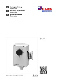
DE
Montageanleitung
Thermostat
UK
Mounting instructions
Thermostat
FR
Notice de montage
Thermostat

MAICO
VENTILATOREN
natural_image
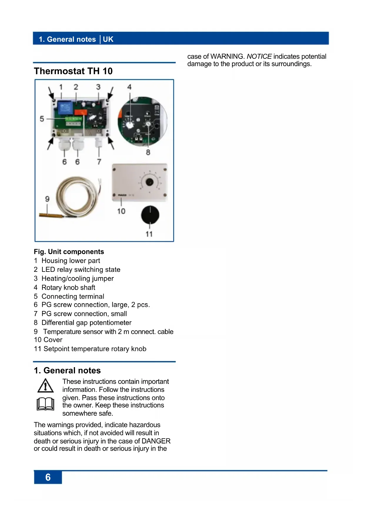
Exterior view of a MAICO TH 10 industrial control device with a coiled hose and temperature scale (no text or symbols on main body)TH 10

text_image
QR code image containing encoded data, no visible human-readable text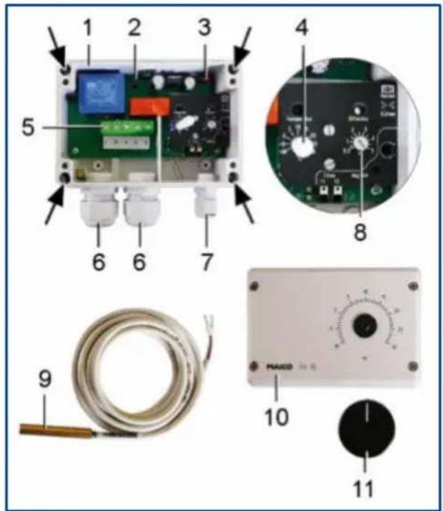
text_image
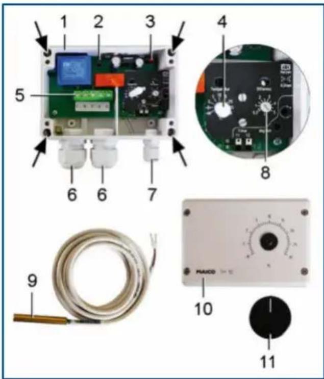
1 2 3 4 5 6 6 7 8 9 MAXO 10 11case of WARNING. NOTICE indicates potential damage to the product or its surroundings.
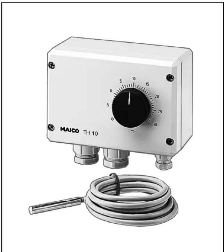
Fig. Unit components
1 Housing lower part
2 LED relay switching state
3 Heating/cooling jumper
4 Rotary knob shaft
5 Connecting terminal
6 PG screw connection, large, 2 pcs.
7 PG screw connection, small
8 Differential gap potentiometer
9 Temperature sensor with 2 m connect. cable
10 Cover
11 Setpoint temperature rotary knob
1. General notes
These instructions contain important information. Follow the instructions given. Pass these instructions onto the owner. Keep these instructions somewhere safe.
The warnings provided, indicate hazardous situations which, if not avoided will result in death or serious injury in the case of DANGER or could result in death or serious injury in the
2. Scope of delivery
Thermostat TH 10 incl. temperature sensor (2 m connection cable) and these mounting instructions.
3. Specialist installer qualification
The thermostat may only be installed by a trained electrician, in line with these instructions. You are deemed competent if you can competently and safely connect units to an electrical power supply in line with the wiring diagram, on the basis of your technical training and experience and are able to recognise and avoid risks and dangers associated with electricity.
4. Intended use
This thermostat is used for controlling fans depending on the air temperature. For indoor deployment. The thermostat is only intended for domestic use and similar purposes.
5. Non-intended use

DANGER
Explosion hazard if operated in an explosive atmosphere in the case of ignition, e.g. from sparks.
Never use the thermostat in an explosive atmosphere.
NOTICE
Unit damage through modifications and alterations. Modifications and alterations to the unit are not permitted and release the manufacturer from any guarantee and liability.
NOTICE
Damage to the unit when used outdoors.
Only use the thermostat in an indoor location.
6. Safety instructions

WARNING
Risks for people (including children) with reduced physical, sensory or mental capabilities or a lack of knowledge.
➢ Thermostat may only be installed, commissioned, cleaned and maintained by people who can safely recognise and avoid the risks associated with this work.

DANGER
Danger from electric shock. Before accessing the connection terminals:
▶ Switch off all supply circuits.
➢ Cover or block off neighbouring live components
- Protect against being accidentally switched back on
➢ Check that there is in fact no voltage present.
7. Function/Operation
When a setpoint temperature is reached, the thermostat switches one or more fans on or off, depending on the settings of the jumpers, in the case of an increasing or a decreasing air temperature (cooling/heating).
The setpoint temperature can be set using the rotary knob [11]. The differential gap between the on/off temperature is determined with potentiometer [8].
8. Technical data
→ Rating plate on the unit.
| Rated voltage | 250 V AC |
| Power frequency | 50/60 Hz |
| Maximum load (inductive load) | 4 A |
| Maximum load (ohmic load) | 10 A |
| Differential gap | 0.2 ... 5 K |
| Radio interference suppression DIN EN 55011 | VDE 0875 Interference level N |
| Degree of protection | IP 54 |
| Protection class | II |
| Type of installation | Surface-mounted |
| Weight | 0.4 kg |
| Dimensions (WxHxD) | 125 x 110 x 69 mm |
9. Environmental conditions and operating limits
| Ambient temperature: | max. + 50°C |
| Temperature setting range | -10 to +30 °C |
10. Storage
Store unit exclusively in a dry location (-20 to +50 °C).
11. Mounting
11.1 Mounting instructions
NOTICE
Incorrect measured values can result from unsuitable installation location. Locate the temperature sensor [9] correctly.
- Avoid disturbing influences.
-
Avoid exposure to direct sunlight.
Do not use in an area prone to draughts, hot or cold air, e.g. near stove, fridge, radiator, refrigerator, air intake, disk valve/internal grille, etc.
Do not install in a unit with other heat-generating devices, e.g. a dimmer switch. -
Only install unit onto a dry, level surface. Any installation position can be selected.
- Only connect the unit to a permanently wired electrical installation after it has been completely mounted.
- The unit may only be operated using the voltage and frequency shown on the rating plate.
- Be sure to observe the relevant regulations for electrical installation; in Germany this is particularly VDE 0100, with the corresponding parts.
- Connection area for the PG screw connection [6] is suitable for connection cables with an external diameter of 6 to 12 mm.
- Connect the temperature sensor to both "sensor" connectors. Permitted cables: max. 100 m long, 1.5 mm ^2 .
- Connection terminals for cable with a max. cross section of 2.5 mm ^4 .
- A mains isolation device with contact openings of at least 3 mm at each pole is mandatory.
- Cooling or heating operating mode can be set with jumpers. Switching state display with LED [2].
- The degree of protection is only guaranteed if installation is undertaken correctly and if the cables are correctly fed into the housing.
11.2 Unit mounting
- Switch off power supply circuits and prevent them from being started up again. Attach a clearly visible warning sign.
- Pull the rotary knob [11] off.
- Remove the cover [10] (4 screws).
- Use 4 screws to secure the bottom part of housing to the wall. Suitable mounting material is to be supplied by the customer.
- Set the operating mode to heating or cooling with jumper [3] (factory setting - heating).
- Set the differential gap between the on/off temperature with the potentiometer [8] (setting range 0.2...5 K).
NOTICE
Danger of short-circuits caused by damp if the connection cable is not inserted in the housing correctly.
➢ Ensure that the rubber seals on the PG screw connections tightly surround the cables.
- Feed the mains power cable through the PG screw connection [6] and the temperature sensor connection cable through the PG screw connection [7] into the housing. Secure the connection cables with the PG screw connections (the rubber seals on the PG screw connections must surround the cables tightly).
- Connect up the connection cables as shown in the wiring diagram ( Chapter 16). Check the wiring and if necessary, tighten the screws in the connection terminals.
- Remount the cover [10] (4 screws) and refit the rotary knob [11]. Make sure that the rotary knob shaft [4] is not damaged and that the rubber seal fits tightly round the shaft.
- Install the fan(s) in accordance with their operating instructions.
12. Start-up
- Check that the technical data has been adhered to rating plate.
- Switch the mains fuse on. Set the setpoint temperature using the rotary knob [11].
- Run function test.
13. Cleaning
Clean the housing and the temperature sensor regularly using a dry cloth.
Fault rectification should only be carried out by a trained electrician.
Check the relay switching state before fault rectification: LED [2] lights up if the relay is energised (terminals 4 and 5 closed).
15. Disassembly and disposal
Dismantling should only be carried out by a trained electrician.
Old devices and electronic components may only be dismantled by specialists with electrical training. Proper disposal avoids detrimental impact on people and the environment and allows valuable raw materials to be reused with the least amount of environmental impact.

Do not dispose of the following components in household waste!
Old devices, wearing parts (e.g. air filter), defective components, electrical and electronic scrap, environmentally hazardous liquids/oils, etc. Dispose of them in an environmentally friendly manner and recycle them at the appropriate collection points ( Waste Management Act).
- Separate the components according to material groups.
- Dispose of packaging materials (cardboard, filling materials, plastics) via appropriate recycling systems or recycling centres.
-
Observe the respective country-specific and local regulations.
-
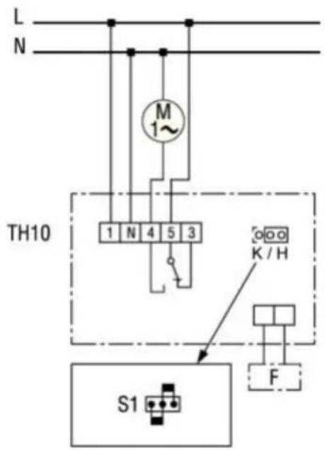
Wiring diagram
text_image
L N M 1~ TH10 1 N 4 5 3 K / H S1 FTH 10 combined with fan
Terminal 3 Cooling
Terminal 4 Heating
F Temperature sensor
M Fan
S1 Jumper:
K: Cooling / H: Heating
Thermostat TH 10