EAT 6 G1 - Thermostat Maico - Free user manual and instructions
Find the device manual for free EAT 6 G1 Maico in PDF.
| Brand | Maico |
| Model | EAT 6 G1 |
| Product type | Temperature control thermostat for fan |
| Dimensions (W x H x D) | 188 x 159 x 110 mm |
| Temperature sensor dimensions | 8.7 x 13 x 4.5 mm |
| Power supply | 230 V AC, 50 Hz, 0.2 to 6 A eff. |
| Protection type | IP 54 |
| Maximum fluid temperature | +40 °C |
| Setpoint temperature range | 5 to 35 °C |
| XP adjustment range | 2 to 10 K |
| Operating modes | Automatic, Off, Continuous |
| Main functions | Thermostatic regulation of room temperature, limit value cut-off, 0-10 V output for optional power element |
| LED indicators | Green (on), yellow (limit value cut-off), red (sensor fault) |
| Maintenance | No maintenance required |
| Cleaning | With a soft dry cloth, no cleaning agents |
| Installation | Wall-mounted, by a qualified electrician |
| Safety | Mains disconnection device mandatory, compliance with electrical standards |
| Warranty | Use of original components, modifications not permitted |
| Delivery contents | EAT 6 G1 unit, temperature sensor, protective cover, manual |
Frequently Asked Questions - EAT 6 G1 Maico
User questions about EAT 6 G1 Maico
0 question about this device. Answer the ones you know or ask your own.
Ask a new question about this device
Download the instructions for your Thermostat in PDF format for free! Find your manual EAT 6 G1 - Maico and take your electronic device back in hand. On this page are published all the documents necessary for the use of your device. EAT 6 G1 by Maico.
USER MANUAL EAT 6 G1 Maico
Installation and operating instructions
for temperature control system
FR
text_image
Automotive Auto Drawer 10°C 30°C MAICO CE CA
text_image
1 2 3 4 5 6 Automatik Aus Dauer 10°C 30°C MAICO 7 8 9 10 11 CE C S Long Long Long Long Long Long Long Long Long Long Long Long Long Long Long Long Long Long Long Long Long Long Long Long Long Long Long Long Long Long Long Long Long Long Long Long Long Long Long Long Long Long Long Long Long
natural_image
Close-up of a mechanical component with mounting holes and a small black component labeled '13' (no readable text or symbols beyond the number)
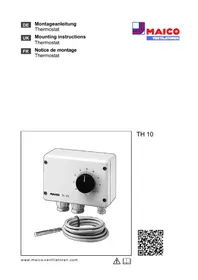
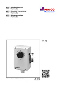
Temperature control system EAT 6 G/1

Please read the instructions carefully before mounting and using for the first time. Follow the instructions. Pass these instructions onto the owner for safekeeping.
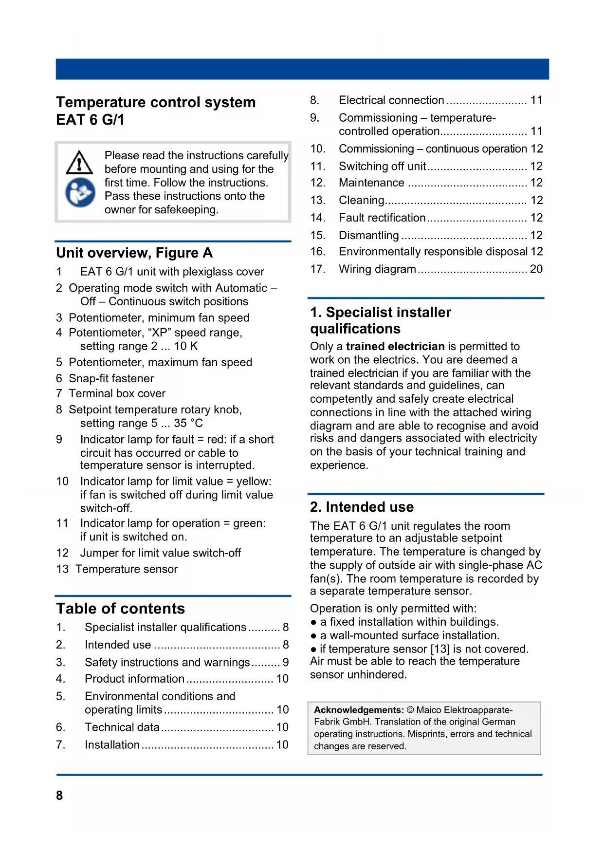
Unit overview, Figure A
1 EAT 6 G/1 unit with plexiglass cover
2 Operating mode switch with Automatic – Off – Continuous switch positions
3 Potentiometer, minimum fan speed
4 Potentiometer, "XP" speed range, setting range 2 ... 10 K
5 Potentiometer, maximum fan speed
6 Snap-fit fastener
7 Terminal box cover
8 Setpoint temperature rotary knob, setting range 5 ... 35 °C
9 Indicator lamp for fault = red: if a short circuit has occurred or cable to temperature sensor is interrupted.
10 Indicator lamp for limit value = yellow: if fan is switched off during limit value switch-off.
11 Indicator lamp for operation = green: if unit is switched on.
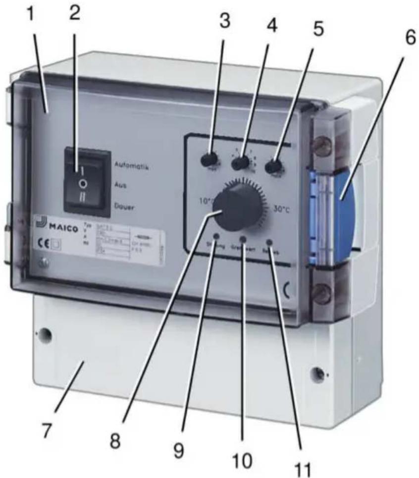
12 Jumper for limit value switch-off
13 Temperature sensor
Table of contents
- Specialist installer qualifications......8
- Intended use 8
- Safety instructions and warnings...... 9
- Product information.... 10
- Environmental conditions and operating limits.... 10
- Technical data.... 10
-
Installation....10
-
Electrical connection.... 11
- Commissioning – temperature-controlled operation.... 11
- Commissioning – continuous operation 12
- Switching off unit.... 12
- Maintenance 12
- Cleaning.... 12
- Fault rectification.... 12
- Dismantling 12
- Environmentally responsible disposal 12
- Wiring diagram....20
1. Specialist installer qualifications
Only a trained electrician is permitted to work on the electrics. You are deemed a trained electrician if you are familiar with the relevant standards and guidelines, can competently and safely create electrical connections in line with the attached wiring diagram and are able to recognise and avoid risks and dangers associated with electricity on the basis of your technical training and experience.
2. Intended use
The EAT 6 G/1 unit regulates the room temperature to an adjustable setpoint temperature. The temperature is changed by the supply of outside air with single-phase AC fan(s). The room temperature is recorded by a separate temperature sensor.
Operation is only permitted with:
- a fixed installation within buildings.
- a wall-mounted surface installation.
- if temperature sensor [13] is not covered. Air must be able to reach the temperature sensor unhindered.
Acknowledgements: © Maico Elektroapparate-Fabrik GmbH. Translation of the original German operating instructions. Misprints, errors and technical changes are reserved.
3. Safety instructions and warnings
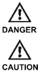
Indicates a hazardous situation which will result in death or serious injuries if not avoided.
Indicates a possibly hazardous situation, which could result in minor to moderate injuries.
The unit must not be used in the following situations under any circumstances.
Risk of combustion/fire from flammable materials, liquids or gases in the vicinity of the unit. Do not place any flammable materials, liquids or gases near the device, which may ignite in the event of heat or sparks and catch fire.
Explosive gases and dusts may ignite and cause serious explosions or fire. Never use unit in an explosive atmosphere (risk of explosion).
Observe all safety instructions.
Risks for children and people with reduced physical, sensory or mental capabilities or a lack of knowledge. Unit may only be installed, commissioned, cleaned and maintained by persons who can safely recognise and avoid the risks associated with this work.
Danger of electric shock when operating a unit which is damaged or not fully mounted or if changes/modifications are undertaken. Before opening the unit, shut down all supply circuits (switch off mains fuse), secure against being accidentally switched back on and position a
visible warning sign. Only operate the unit when it is completely installed. Do not commission a damaged unit. The unit may only be operated with original components. Changes and modifications are not permitted and release the manufacturer from any guarantee obligations and liability, e.g. if the unit is drilled at a point which is not permitted.
Danger if the relevant regulations for electrical installations are not observed.
→ Before installing the electrics, shut down all supply circuits, deactivate the mains fuse and secure it so it cannot be switched back on. Attach a warning sign in a clearly visible place.
→ Be sure to observe the relevant regulations for electrical installation; e.g. DIN EN 50110-1, in Germany this is particularly VDE 0100, with the corresponding parts.
→ A mains isolation device with contact openings of at least 3 mm at each pole is mandatory.
→ Only connect unit to a permanently wired electrical installation with NYM-O / NYM-J, 3 x 1.5 mm ^2 cables.
→ The units may only be operated using the voltage and frequency shown on the rating plate.
→ The degree of protection stated on the rating plate is only guaranteed if installation is undertaken correctly and if the connection cable is correctly guided through the cable grommet(s). The grommets must tightly seal the cable sheathing.
→ Maintenance and fault finding only permissible when carried out by trained specialists.
Exercise caution when handling packaging materials. Observe applicable safety and accident prevention requirements. Store packaging material out of the reach of children.
4. Product information
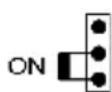
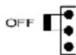
Operating modes with switch [2]
- Automatic operation (=temperature-controlled operation): Room temperature is changed by the supply of outside air with fan until the setpoint temperature selected with rotary knob [8] is reached, see "Temperature control". Green indicator light [11] lights up.
- Off: Fan switches off, green indicator light [11] is off.
- Continuous operation: Fan runs at set minimum speed. Green indicator light [11] lights up.
Temperature control
- When the unit is switched on with switch [2], the fan starts up at maximum speed. The speed is then reduced in proportion to the change in temperature on the temperature sensor [13].
- If the room temperature is above the setpoint temperature, the fan speed increases to the maximum value set with potentiometer [5].
- The fan speed decreases as the room temperature falls through the supply of cold outside air, for example. At setpoint temperature, the minimum value set with potentiometer [3] is reached.
- "XP" speed range: Potentiometer [4] is used to define how quickly the maximum fan speed is to be reached. Fan runs at maximum speed for "setpoint temperature + adjustable value". For example, when "XP = 5", the maximum fan speed is reached at a room temperature 5 K above the setpoint temperature.
- If the room temperature falls at least 3 °C below the setpoint temperature, the fan speed is either – controlled using limit value switch-off. The fan switches off automatically until setpoint temperature is reached again. – or the fan runs constantly at minimum speed. Setting is made using jumper [12]. Ex factory = limit value switch-off “On”.
Dimensions
- EAT 6 G/1 unit (W x H x D): 188 x 159 x 110 mm
- Temperature sensor (W x H x D): 8.7 x 13 x 4.5 mm
Power supply
- Rated voltage: 230 V
- Nominal current range: 0.2 A eff. to 6 A, eff.
• Power frequency: 50 Hz
Protection class
- Degree of protection: IP 54 (splash water protected)
5. Environmental conditions and operating limits
- Maximum permitted temperature of the air medium: +40 °C
6. Technical data
- Refer to the rating plate and/or valid catalogue.
7. Installation
➢ Select installation location for EAT 6 G/1 unit [1] and make sure there is a flat surface.
➢ Select installation location for temperature sensor [13]:
- High up in the room.
- Not in a corner.
- Temperature sensor may only be installed pointed downwards.
➢ Lay cables, for permitted types see chap. 4: – Use 2-core control cable between EAT 6 G/1 unit and temperature sensor and – use 3-core control between EAT 6 G/1 unit and fan.
▶ Lay power cable.
➢ Fit central screw for EAT 6 G/1 unit. For spacing, refer to rear of unit. Suitable mounting material is to be provided by the customer.
➢ Remove terminal box cover [7] from EAT 6 G/1 unit [1].
➢ Cut through desired cable lead-throughs at knockout points on underside of EAT 6 G/1 housing.

Unit will be damaged by water ingress or moisture.
Only lead cables into EAT 6 G/1 housing from underneath. If this is not done, the degree of protection cannot be guaranteed.
➢ Hang EAT 6 G/1 unit on central screw and secure in the bottom right and left with 2 locking bolts. Suitable mounting material is to be provided by the customer.
➢ Guide all connecting cables into the housing.
➢ Remove cover from temperature sensor [13].
➢ Cut through desired cable lead-through at one knockout point on side of temperature sensor housing.
▶ Fit cable grommet on housing.
➢ Fit temperature sensor housing on wall. For spacing, refer to rear of housing. Suitable mounting material is to be provided by the customer.
▶ Feed cable into the housing.
8. Electrical connection

Risk of damage to unit in the event of short-circuits!
➢ Cut off and insulate cable cores that are not required.
information
- EAT 6 G/1 unit is fitted with a 0...10 V output for optional EALT 6 power unit (for permitted maximum loading = 12 A).
- The output voltage at EALT 6 (+/- terminal) is proportional to the controlled 0...10 V voltage.
Connecting temperature controller
▶ Strip cables.
➢ Connect power cable and control cables as shown in wiring diagram on page 7.
➢ Fit cover on temperature sensor [13]. Ensure that the sealing in the cover is inserted correctly and is sealed all the way around.
➢ Check position of jumper [12] in EAT 6 G/1 terminal box and move if desired:
Limit value switch, On.
Fan switches off when temperature falls below setpoint temperature by at least 3 °C and switches back on when setpoint temperature is exceeded.
Limit value switch, Off.
Fan runs at minimum speed when temperature falls below setpoint temperature by at least 3 °C.
➢ Fit terminal box cover [7] on EAT 6 G/1 unit [1].
▶ Switch the mains fuse on.
➢ Run function test.
9. Commissioning – temperature-controlled operation
➢ Move operating mode switch [2] into "Automatic" position.
- Unit switches on.
➢ Use potentiometer [5] to set “XP” speed range:
- All the way to the left, approx. 2 K
– All the way to the right, approx. 10 K
➢ Use rotary knob [7] to select setpoint temperature. Setting range 5...35 °C.
➢ Use potentiometer [6] to select maximum fan speed.
➢ Use potentiometer [4] to select minimum fan speed.
10. Commissioning – continuous operation
➢ Move operating mode switch [2] into "Continuous" position.
- Unit switches on. Fan runs at set minimum speed.
11. Switching off unit
➢ Move operating mode switch [2] into “Off” position.
12. Maintenance
The unit is maintenance-free.
13. Cleaning
If dusty, clean the unit with a soft, dry cloth. Do not use cleaning agents.
- Call on the services of a qualified electrician any time there is a fault!
- Repairs should only be carried out by a qualified electrician!
DANGER
Danger to life. Unit is powered up!
▶ Switch the mains fuse off!
| Fault | Measure |
| In the event of a short circuit or if cable to temperature sensor is interrupted, the fan will run at minimum speed. Red indicator light [9] switches on. | Call on the services of a qualified electrician. |
| Micro-fuse has tripped. | Call on the services of a qualified electrician. |
Tab.1: Fault rectification
15. Dismantling
Dismantling should only be carried out by a trained electrician.
16. Environmentally responsible disposal
The unit and the packaging contain parts that can be recycled, and should not end up in the domestic waste. Dispose of the packaging material in an environmentally-friendly way, in compliance with the regulations valid in the country where you are.
At the end of its service life, dispose of the unit in an environmentally-friendly way, in compliance with the regulations valid in the country where you are.
EAT 6 G/1 mit/with/avec EALT 6:
Temperature controller with power unit