DriForce - Heating Dri Eaz - Free user manual and instructions
Find the device manual for free DriForce Dri Eaz in PDF.
User questions about DriForce Dri Eaz
0 question about this device. Answer the ones you know or ask your own.
Ask a new question about this device
Download the instructions for your Heating in PDF format for free! Find your manual DriForce - Dri Eaz and take your electronic device back in hand. On this page are published all the documents necessary for the use of your device. DriForce by Dri Eaz.
USER MANUAL DriForce Dri Eaz
Models F211, F211-AK, F211-BU
Legend Brands, Inc.
15180 Josh Wilson Road, Burlington, WA 98233
Phone: 800-932-3030 Fax: 360-757-7950 LegendBrandsRestoration.com
The DriForce InterAir Drying System allows the restorer to direct high-pressure air into wet walls, behind cabinets, and into other hard-to-reach structures with minimal disruption to materials. Provides fast, effective drying in all types of assemblies and materials.
Patents: www.LBpatents.com
READ AND SAVE THESE INSTRUCTIONS

WARNING
WARNING! To reduce the risk of fire or electric shock, do not use this fan with any solid-state speed control device.
WARNING! Unit must be grounded. Do not use with an extension cord. Connect only to an outlet provided with a ground fault interrupting device.
WARNING! Do not touch grills when unit is operating.
NOTICE: Keep motor dry. For indoor use only.
NOTICE: Unplug when not in use or when moving unit.
WARNING: Do not allow children to play with or around the unit. Be sure the unit is inaccessible to children when not attended.
NOTICE: Always operate the unit on a stable, level surface so it cannot fall and cause injury.
WARNING! Do not alter or modify your Dri-Eaz product in any way. Use only replacement parts authorized by Legend Brands Restoration, Inc. Modifications or use of unapproved parts could create a hazard and will void your warranty. Contact your authorized Dri-Eaz distributor for assistance.
WARNING!
a) Do not operate any fan with a damaged cord or plug. Discard fan or return to an authorized service facility for examination and/or repair.
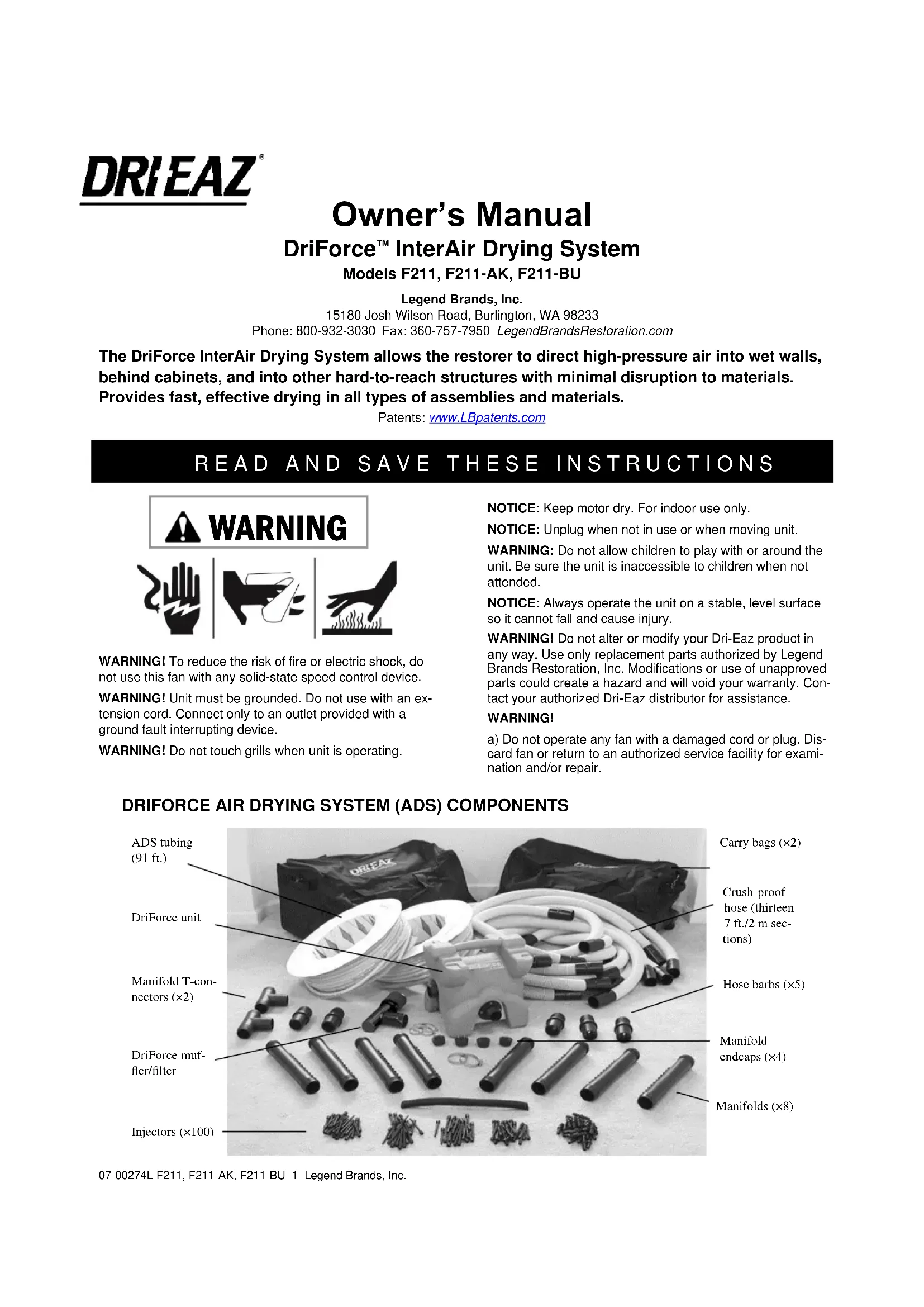
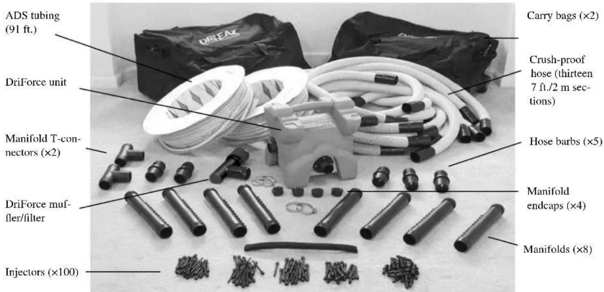
DRIFORCE AIR DRYING SYSTEM (ADS) COMPONENTS
text_image
ADS tubing (91 ft.) DriForce unit Carry bags (×2) Crush-proof hose (thirteen 7 ft./2 m sec- tions) Manifold T-con- nectors (×2) Hose barbs (×5) DriForce muff- fler/filter Manifold endcaps (×4) Injectors (×100) Manifolds (×8)DRIFORCE BLOWER
text_image
GEQIEC VEGETABLE Vacuum IN Wrap cord around unit when not in use. ON/OFF switch in base (not shown) Blower OUTb) Do not run cord under carpeting. Do not cover cord with throw rugs, runners, or similar coverings. Do not route cord under furniture or appliances. Arrange cord away from traffic area and where it will not be tripped over.

WARNING: This product and other substances that may become airborne from its use contain chemicals, including lead and phthalates, known to
the State of California to cause cancer, birth defects, or other reproductive harm. For more information, go to P65Warnings.ca.gov
BEFORE YOU BEGIN
Warranty registration
Please visit warranty.drieaz.com to register your purchase. Registration allows us to better assist you with using, maintaining or servicing your equipment and to contact you in case we have important safety information concerning your Dri-Eaz product. If you determine service is required, have your equipment model, serial number and original proof of purchase available and call your distributor for assistance with obtaining a return material authorization (RMA).
OPERATING INSTRUCTIONS
IMPORTANT: Extract standing water before attempting to dry. Do NOT use the DriForce to extract standing water of any kind.
Tools
Pencil, tape measure, razor knife, drywall taping knife, small pry bar, nail puller, screw driver, a carpet awl, a drill with a 3/16 in. bit. An electronic stud finder is also useful.
Preparing Walls, Cabinets and other Assemblies for Drying
Walls
Wall drying using an inter-air drying system can be accomplished with or without baseboards present. After inspecting walls, insulation, and baseboards, and after evaluating paint finish considerations, proceed in the manner that delivers the most value to the customer.
Remove baseboard or cove base. First, use a razor knife to score along the top of the base where it meets the wall, to reduce damage to the painted surfaces and make a professional re-installation easier. When prying base away from 07-00274L F211, F211-AK, F211-BU 2 Legend Brands, Inc.
the wall, protect the wall surface by inserting a drywall knife between the pry bar and the wall. Pull remaining nails out of the wall, or through the back of the baseboard. Write a number on the wall and the corresponding base so you will know where to reinstall it. However, drying success can also be achieved by making the wall penetrations immediately above the top of baseboard and proceeding to dry with the baseboards in place. This is a necessary procedure where there is a desire to save a wall with a tiled wall base, when value is added by avoiding the detachment of wall baseboards.
Making air access holes
Punch holes with a carpet awl or use a drill with a 3/16 in. bit. Create at least one hole between each set of studs and about 2 in. above the floor. An electronic stud finder can be used to locate studs and find the center of the cavity.
Larger holes are more time-consuming to patch, and may decrease efficiency by leaking air. Try to reduce the need for later repairs by placing the holes behind the rubber wainscoting or cove base, or behind trim that is easily reinstalled over the holes.
Steel Studs
Steel studs are common in commercial buildings. They are set in a channel that can hold large volumes of water. To access these areas, drill holes approximately 12 inch from
natural_image
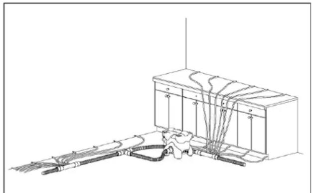
Technical line drawing of a mechanical assembly with hoses and connectors (no text or symbols)The DriForce and the Air Drying System can deliver air to structural cavities in walls, ceilings, under and above cabinets, and many other areas.
natural_image
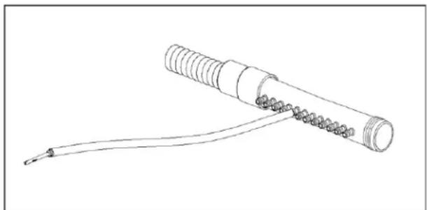
Line drawing of a mechanical connector with threaded end and coiled cable (no text or symbols)The ADS connects to the DriForce blower outlet and attaches to a manifold with a standard hose cuff. Supply tubes run from the manifold to injectors that are inserted into a wall or other structural cavity.
the floor at a downward angle. Take care, however, not to immerse the ends of the tubes in any standing water that may be present.
Ceilings and Cabinets
The larger lumber sizes and structural cavities in ceilings will require more air airflow to dry properly.
Moisture under and behind cabinets may be difficult to detect, but it is safest to assume that moisture is present if water has flowed through these assemblies. Make sure to provide as much airflow as possible. If you cannot properly access all interior spaces, the cabinets may need to be removed.
NOTICE: Do not use the DriForce to extract liquid water or debris of any kind. This may damage the unit and void the warranty.
text_image
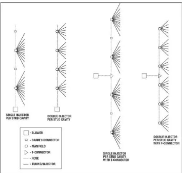
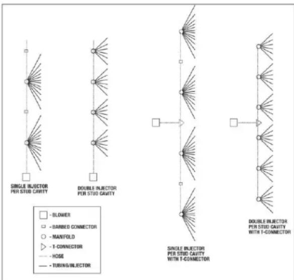
SINGLE INJECTOR PER STUD CAVITY DOUBLE INJECTOR PER STUD CAVITY - BLOWER - BARBED CONNECTOR - MANIFOLD - T-CONNECTOR - HOSE - TUBING/INJECTOR SINGLE INJECTOR PER STUD CAVITY WITH T-CONNECTOR DOUBLE INJECTOR PER STUD CAVITY WITH T-CONNECTORDiagram shows two inline ADS lines (left), and two double-ADS lines running from a T-fitting. It also shows tubing layouts for one or two injectors into each wall cavity.
DriForce Blower Setup
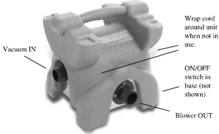
The DriForce Blower is equipped with a blower outlet, a vacuum inlet, a power switch and a power cord. Plug in unit to an appropriate grounded 115V outlet rated for 15 amps.
Attach vacuum hoses to the vacuum inlet and/or blower outlet.
Set the DriForce blower out of high traffic areas to minimize a trip-and-fall hazard from the blower and the ADS.
NOTE: The muffler/filter supplied with the DriForce should only be installed when using the DriForce in the Air Injection (Blower) mode, described under Phase 2 below. Do not use the muffler-filter when using with the DriForce in the air extraction mode (Phase 1). The filter is not intended to be used on the inlet (vacuum) side of the DriForce.
Switch power on and off with the toggle switch, found in the base of the unit.
Air Drying System (ADS) Setup
Manifold configuration
Next, determine the number of manifolds needed for the job. The following setup will deliver 25 to 30 air exchanges per hour in each cavity, which is effective for most situations. Use a formula of one manifold (each manifold has 12 injectors) for each 14 feet of interior 2 × 4 framed wall. For 2 × 6 exterior framed walls, common walls in apartments and condos, double-sheeted fire walls, and dense or water-resistant covered walls, use a formula of one manifold (12 injectors) for each 7 feet of wall.
After determining the number and length of hose assemblies and manifolds, set up the ADS system. Pre-assembling the manifolds, tubing and injectors will save considerable time.
Supply tube configuration
Two 200 ft. (60 m) lengths of 38 in. (0.375 mm) ID air supply tubing are provided. This tubing can be cut to length with a pair of sturdy scissors or a utility knife. We recommend the cutting following tubing lengths to create a setup suitable for most standard wall-drying jobs:
- Set up THREE manifolds with the following lengths of tubing:
| Manifold no. | Tubing quantity | Tubing length | Tubing locations on manifold outlets |
| 1 | 4 | 4 ft. 1.2 m | Outlets 1, 2, 11 and 12 |
| 2 | 4 | 3 12 ft. 1 m | Outlets 3, 4, 9 and 10 |
| 3 | 4 | 1 ft. 30 cm | Outlets 5, 6, 7 and 8 |
- Set up the remaining FIVE manifolds with the following lengths of tubing:
| Manifold no. | Tubing quantity | Tubing Length | Tubing locations on manifold outlets |
| 4 | 2 | 712 ft. 2.3 m | Outlets 1 and 12 |
| 5 | 2 | 612 ft. 2.0 m | Outlets 2 and 11 |
| 6 | 2 | 512 ft. 1.7 m | Outlets 3 and 10 |
| 7 | 2 | 412 ft. 1.4 m | Outlets 4 and 9 |
| 8 | 2 | 212 ft. 0.8 m | Outlets 5 and 8 |
| 9 | 2 | 1 ft. 30 cm | Outlets 6 and 7 |
To install the tubing, slide the one end of the tubing over the manifold outlet nipple and insert an injector in the other end.
Tightly seal off the last manifold on each run of ADS with an end-cap plug. Now place the injectors into the holes you have drilled or punched in the wall, cabinet or other assembly.
Ensure that all T-fittings, hose cuffs, manifolds, supply lines, and injectors are properly installed. Attach the ADS to the DriForce. Plug in the DriForce and switch it on briefly, checking all connections for air leakage. If needed, use a hose clamp to seal off any air leakage where the vinyl products connect up to hose barbs, etc.
Drying Procedure
Phase 1: Air Extraction (Vacuum) Drying
Attach the ADS to the vacuum inlet of the DriForce blower unit and switch unit on.
Use the air extraction (vacuum) mode to draw humid air from structural cavities.
Operate Phase 1 until the humidity of the air being drawn from the affected area is approximately the same as the humidity in an unaffected area of the job. You can use a hygrometer to compare RH readings between the outlet of the DriForce and the surrounding area.
NOTE: Be sure to attach the vacuum hose to the DriForce outlet and direct the exhaust air outside the structure. Do not use the muffler-filter that is supplied with the DriForce in the air extraction mode. This filter is not a HEPA-grade filter, and will not properly capture contaminants that may be drawn into the DriForce. Use the muffler-filter only in the injection (blower) mode, described below.
Phase 2: Air Injection (Blower) Drying
Attach the ADS from the vacuum to the pressure outlet of the DriForce, install the muffler-filter on the air intake, and switch unit on.
Once the humidity inside the structural cavity equals the humidity in the room, it is time to switch to the air injection mode. Injecting room air into the structural cavities will help continue the drying process. This is especially true if you are dehumidifying the room air.
TIP: When drying inside walls, use an awl-punch or drill to create a small vent holes placed just above the highest moisture point on the wall. This will provide a vent and help to speed up the drying process by allowing greater air flow through the affected materials. A small hole can be easily patched.
TIP: To maximize drying in walls that wainscoted, tile-covered, double-sheeted, or covered with vinyl wall paper or impermeable paint, as well as lath and plaster walls, firewalls and insulated walls, place additional injectors per linear foot.
TIP: Accelerate drying with dehumidifiers. To increase drying rates during Phase 2, use a dehumidifier to supply dry air directly into the DriForce. Position the dry air outlet of a dehumidifier near the DriForce air inlet, or duct the dehumidifier outlet toward the DriForce inlet. Desiccant dehumidifiers are especially useful for this purpose, as the extremely dry air they produce can accelerate the drying of dense materials and assemblies.
NOTICE: Do NOT tape or seal the dehumidifier ducting to the DriForce inlet, as this could unbalance the airflow through the dehumidifier and possibly damage the dehumidifier.
Odor and Mold Control
If you suspect that mold and mildew may be growing inside cavities, follow the appropriate industry mold remediation procedures and safety standards.
MAINTENANCE
WARNING: Always unplug unit prior to servicing or cleaning.
As needed
Check both the inlet and outlet of the DriForce unit for obstructions or debris after each use.
Inspect the muffler-filter, and clean as needed by vacuuming or washing. Check manifolds, tubing, injectors and other ADS components, and replace if needed.
Clean the exterior of the DriForce and ADS components with a vinyl cleaner and protectant.
Parts, service, and maintenance and warranty information are available from your Dri-Eaz distributor.
| SPECIFICATIONS | |
| DriForce InterAir Drying System (F211) | |
| BASE UNIT | |
| Dimensions (H × L × D) | 14 × 14 × 12 in. | 35 × 35 × 30 cm |
| Amperage | 5.4 amps |
| Power | 115V / 60Hz |
| Total system airflow (max.) | 100 CFM | 2.3 CMM |
| Working static pressure (water lift) | 38 in. | 97 cm |
| Weight (base unit only) | 14.5 lbs. | 6.3 kg |
| Safety | ETL listed to UL 507 and CSA C22.2 No. 113 |
| AIR DELIVERY SYSTEM (ADS) | |
| Crush-proof ADS tubing | 91 ft. (28 m).of 11⁄2 in. (3.8 cm) tubing. Pre-cut into thirteen 7 ft. (2 m) sections. |
| Injector hole size | Less than 1⁄4 in. (6 mm) |
| Flexible tubing | 400 ft. (122 m) of 3⁄8 in. (0.375 mm) ID tubing |
| Carrying/storage system | 2 suitcase-style duffle bags with handle and wheels |
| Drying modes | Either positive or negative pressure |
| Parts included | 100 injectors, 8 manifolds (12 outlets each), 4 manifold endcaps, 4 coupler fittings, 2 hose clamps, 2 T-fittings, 13 hose assemblies with cuffs, 25 tube extender connections, 1 muffler. |
natural_image
Technical line drawing of a mechanical assembly with hoses and components (no text or symbols)natural_image
Line drawing of a coiled wire or filament with threaded ends, no text or symbols present15180 Josh Wilson Road, Burlington, WA 98233 É.-U.
natural_image
Technical line drawing of a mechanical assembly with hoses and components (no text or symbols)natural_image
Line drawing of a coiled wire or filament with threaded ends, no text or symbols present07-00274L F211, F211-AK, F211-BU 12 Legend Brands, Inc.