VC125 - Multimeter VOLTCRAFT - Free user manual and instructions
Find the device manual for free VC125 VOLTCRAFT in PDF.
User questions about VC125 VOLTCRAFT
0 question about this device. Answer the ones you know or ask your own.
Ask a new question about this device
Download the instructions for your Multimeter in PDF format for free! Find your manual VC125 - VOLTCRAFT and take your electronic device back in hand. On this page are published all the documents necessary for the use of your device. VC125 by VOLTCRAFT.
USER MANUAL VC125 VOLTCRAFT
a) Switching on the Multimeter 32
b) Voltage Measuring "V" 33
c) Direct Current Measuring "A DC" 34
c) Direct Current Measuring "mA/μA DC" 35
e) Resistance Measuring 36
f) Acoustic Continuity Test 36
g) Diode Test 37
h) Battery Test. 37
- ADDITIONAL FUNCTIONS 38
a) HOLD Function 38
b) Display Lighting 38
- CLEANING AND MAINTENANCE 38
a) General 38
b) Cleaning 39
c) Inserting and Changing the Batteries 39
d) Fuse Change 40
- DISPOSAL 41
- TROUBLESHOOTING 41
- TECHNICAL DATA 42
1. INTRODUCTION
Dear customer,
Thank you for making the excellent decision to purchase this Voltcraft® product.
You have acquired a quality product from a brand family which has distinguished itself in the fields of measuring, charging and grid technology thanks to its particular expertise and its continuous innovation.
With Voltcraft, you will be able to handle difficult tasks, either as an ambitious hobbyist or as a professional user. Voltcraft offers reliable technology and a great price-performance-ratio.
We are positive: Starting to work with Voltcraft will also be the beginning of a long, successful relationship.
Enjoy your new Voltcraft® product!
If there are any technical questions, please contact:
International: www.conrad.com/contact
United Kingdom: www.conrad-electronic.co.uk/contact
2. INTENDED USE
Measuring and displaying electric parameters in the range of measurement category CAT III up to 600V against earth potential, pursuant to EN 61010-1 and all lower measuring categories. The meter must not be used in the measuring category CAT IV.
- Measurement of direct and alternating voltage up to 600V
- Measurement of direct currents up to 10 A
- Measurement of resistances up to 2000k
- Acoustic continuity test (< 30)
- Diode test
- Battery test for 9 V-block and 1.5V round cell batteries
The measurement functions are selected using the dial switch. The measuring range is selected manually for all measuring functions.
The VC-125 shows averages in the AC voltage measuring range. Polarity is automatically indicated with the minus prefix (-) if the measured values are negative.
Use of personal protection equipment is recommended for measurements in CAT III environments. The meter must not be used in the measuring category CAT IV.
The multimeter is operated with a conventional 9V block battery (type 6F22, NEDA1604 or same build). The device must only be operated with the specified battery type. Rechargeable batteries should not be used because of the lower capacity and the resulting shorter operating time.
The multimeter must not be operated when it is open, i.e. with an open battery compartment or when the battery compartment cover is missing.
Measuring in potentially explosive areas (Ex) or damp rooms or under unfavourable ambient conditions is not permitted. Unfavourable ambient conditions are: Moisture or high humidity, dust and flammable gases, fumes or solvents, thunderstorms or thunderstorm conditions like strong electrostatic fields, etc.
For safety reasons, only use measuring lines or accessories which are adjusted to the specifications of the multimeter when measuring.
The meter must only be operated by persons who are familiar with the required provisions for the measurement and the possible dangers. Use of personal protection equipment is recommended.
Any use other than that described above will lead to damage to the product and involves additional risks such as, for example, short circuit, fire, electric shock, etc. No part of this product must be modified or converted!
Read the operating instructions carefully and keep them for later reference.
Always observe the safety information!
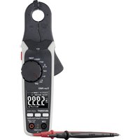
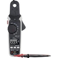
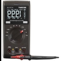
3. OPERATING ELEMENTS
1 Display
2 HOLD button with latching function for holding the measuring display
3 Dial switch for selecting the measuring function
4 10 A-current measuring socket
5 COM measuring socket (reference potential, "minus potential")
6 VΩmA measuring socket ("plus potential")
7 Setup bracket, unfolding
8 Battery compartment
9 Button for display lighting
4. SCOPE OF DELIVERY
Digital multimeter VC-125
- 9V block battery
- 2 safety measuring lines with removable CAT III cover caps
- Operating instructions
5. SAFETY INFORMATION

Please read the operating instructions completely before taking the device into operation. They contain important information for correct operation.
The guarantee/warranty will expire if damage is incurred resulting from non-compliance with the operating instructions! We do not assume any liability for consequential damage!
We do not assume any liability for damage to property or personal injury caused by improper use or the failure to observe the safety instructions! In such cases the warranty/guarantee is voided.
This device left the manufacturer's factory in safe and perfect condition.
To maintain this condition and to ensure safe operation, the user must observe the safety information and warning notes in these operating instructions.
Observe the following symbols:

An exclamation mark in a triangle shows important notes in these operating instructions that must be strictly observed.
The triangle containing a lightning symbol warns against danger of electrical shock or impairment of the electrical safety of the device.

The "arrow" symbol indicates that special advice and notes on operation are provided.

This device is CE-compliance and meets the applicable European directives.

Protection class 2 (double or reinforced insulation)
Attention, read instructions.
CATI
Measuring category I for measurements at electrical and electronic devices that are not directly supplied with mains voltage (e.g. battery-powered devices, protective low voltages, signal and control voltages, etc.)
CAT II
Measuring category II for measurements at electrical and electronic devices connected to the mains supply directly with a mains plug. This category also covers all lower categories (e.g. CAT I for measuring signal and control voltages).
CAT III
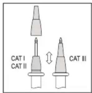
Measuring category III for measuring in building installation (e.g. outlets or sub-distribution). This category also covers all lower categories (e.g. CAT II for measuring electronic devices). Measuring operation in CAT III is only permitted with measuring prods with a maximum free contact length of 4mm or with cover caps above the measuring prods.
CAT IV
Measuring category IV for measurements at the source of the low-voltage installation (e.g. main distribution, building handover points of the energy suppliers, etc.), and outdoors (e.g. work at earthing cable, outdoor line, etc.). This category also contains all lower categories. Measuring operation in CAT IV is only permitted with measuring prods with a maximum free contact length of 4mm or with cover caps above the measuring prods.

Earth potential
For safety and approval reasons (CE), unauthorised conversion and/or modification of the device are not permitted.
Consult an expert when in doubt as to the operation, safety or the connection of the device.
Meters and accessories are not toys and have no place in the hands of children!
In commercial institutions, the accident prevention regulations of the Employer's Liability Insurance Association for Electrical Systems and Operating Materials are to be observed.
In schools, training centres, computer and self-help workshops, handling of meters must be supervised by trained personnel in a responsible manner.
Ensure before every measurement that the meter is not set to another measuring range. Also observe that the HOLD button was not pushed at the beginning of the measurement (display with the HOLD button pushed: "HOLD"). If the HOLD button is pushed at commencement of measuring, no measured value is displayed!
When using the measuring lines without cover caps, measurements between the meter and the earth potential must not be performed above the measuring category CAT II.
When measuring in the measuring category CAT III, the cover caps must be pushed onto the measuring prods to avoid accidental short circuits during measurement.
Push the cover caps onto the measuring prods until they latch. To remove, pull the caps fro the prods with a little force.
The measuring prods have to be removed from the measured object every time the measuring range is changed.
The voltage between the connection points of the meter and earth potential must not exceed 600 V DC/AC in CAT III.
Be especially careful when dealing with voltages higher than 33V alternating (AC) or 70V direct voltage (DC)! Even at these voltages it is possible to receive a potentially fatal electric shock if you touch electrical conductors.
To avoid electric shock, make sure not to touch the connections/measuring points to be measured directly or indirectly during measurement. Never reach beyond the noticeable grip area marks at the measuring prods during measurements.
Check the meter and its measuring lines for damage before each measurement. Never carry out any measurements if the protecting insulation is defective (torn, ripped off etc.). The enclosed measuring cables have a wear indicator. When they are damaged, a second insulation layer in a different colour becomes visible. The measuring accessories must no longer be used and must be replaced.
Do not use the multimeter just before, during or just after a thunderstorm (lightning! / high-energy overvoltage!). Make sure that your hands, shoes, clothing, the floor, circuits and circuit components are dry.
Never operate the product in direct proximity of:
- strong magnetic or electromagnetic fields
- Transmitter aerials or HF generators.
This could affect the measurement.
If you have reason to believe that the device can no longer be operated safely, disconnect it immediately and make sure it is not operated unintentionally. It can be assumed that safe operation is no longer possible if:
- the device shows visible damage
- the device no longer functions
- the device was stored under unfavourable conditions over an extended period of time or
- following considerable stress during transportation.
Do not switch the meter on immediately after it was taken from a cold to a warm environment. The condensation that forms might destroy your device. Allow the device to reach room temperature before switching it on.
Do not leave the packaging material lying around carelessly since such materials can become dangerous toys in the hands of children.
Also observe the safety information in each chapter of these instructions.
6.PRODUCT DESCRIPTION
The multimeter (referred to as DMM in the following) indicates measured values on a digital display that can be illuminated. The measured value display of the DMM comprises 2000 counts (count = smallest display value).
The meter can be used for do-it-yourself or for professional applications up to CAT III.
There are transport protection caps in the angled plugs of the enclosed measuring lines. Remove them before pushing the plugs into the meter sockets.
At the rear, there is an unfolding setup bracket (7) with which the DMM can be set up inclined. This makes it easier to read the display.
Dial switch (3)
The individual measuring functions and ranges are selected via a dial switch.
If the multimeter switch is set to "OFF", the meter is switched off. Always turn the meter off when it is not in use.
7. DISPLAY INDICATIONS AND SYMBOLS
The following symbols and information are present at the device or in the display.
OFF Switch position "off"
HOLD Call/deactivate data hold function Data-Hold function is active
OL Overflow display, the measuring area was exceeded

Battery change symbol. When this symbol appears in the display, the battery must be replaced at once to avoid measuring errors!

Symbol for the battery data used

Symbol for the diode test

Symbol for the acoustic continuity tester

AC Symbol for alternating current

DC Symbol for direct current
V, mV Volt (unit of electric voltage), Milli-Volt (exp.-3)
A, mA, A Ampere (unit of electric current),
Milli-Ampere (exp.-3), Micro-Ampere (exp.-6)
kΩ Ohm (unit of electrical resistance), Kilo-Ohm (exp.3)

Button to switch the display lighting on and off

Symbol for the fuses used
BATT. Measuring function for battery test
8. MEASURING
Do not exceed the maximum permitted input values. Do not touch any circuits or parts of circuits if they may be subject to voltages higher than 33 V ACrms or 70 V DC! Danger to life!
Before measuring, check the connected measuring lines for damage such as, for example, cuts, cracks or squeezing. Defective measuring lines must no longer be used! Danger to life!
During measuring, do not grip beyond the tangible grip range markings present on the measuring prods.
Only the two measuring lines that are required for measuring operation must be connected to the meter at any time. Remove all measuring lines not required from the meter for safety reasons before performing the measurement.
Measurements in electrical circuits >33V / AC and >70V / DC must only be carried out by specialists and technically instructed personnel who are familiar with the relevant regulations and the ensuing risks.
Ensure before every measurement that the meter is not set to another measuring range. Also observe that the HOLD button was not pushed at the beginning of the measurement (display with the HOLD button pushed: "HOLD"). If the HOLD button is pushed at commencement of measuring, no measured value is displayed!
Observe the required safety notes, provisions and safety measures for intrinsic protection.

Always start your measurements with the largest measuring range. Then switch to the next-lower measuring range on demand. Before a measuring range change, always remove the measuring prods from the measuring object. Once shows "OL" (= overflow), you have exceeded the measuring range.
a) Switching on the Multimeter
The multimeter can be turned on and off using the dial switch. Turn the dial switch (3) to the corresponding measurement function. To switch off, turn the dial switch to "OFF". Always turn the meter off when it is not in use.

Before working with the meter, you have to insert the enclosed battery. Insertion and changing of the battery is described in the chapter "Cleaning and Maintenance".
b) Voltage Measuring "V"
Proceed as follows to measure direct voltages (V):
- Switch on the DMM and select the respective measuring range "V DC".
- Plug the red measuring line into the V measuring jack (6) and the black measuring line into the COM measuring jack (5).
- Connect the two measuring prods to the object to be measured (battery, circuit, etc.). The red measuring prod indicates the positive pole, the black measuring prod the negative pole.
- The current measured value is indicated on the display.
- Remove the measuring lines from the object to be measured after completion of the measurement and switch off the DMM.


If a minus “-” appears in front of the measured value for direct voltage, the measured voltage is negative (or the measuring lines are swapped).
The voltage range "V DC" has an input resistance of >1 MOhm.
Proceed as follows to measure alternating voltages "AC" (V)
- Switch on the DMM and select the respective measuring range "V AC".
- Plug the red measuring line into the V measuring jack (6) and the black measuring line into the COM measuring jack (5).
- Connect the two measuring prods to the object to be measured (battery, mains voltage, etc.).
- The current measured value is indicated on the display.
- Remove the measuring lines from the object to be measured after completion of the measurement and switch off the DMM.

The voltage range V AC" has an input resistance of >1M
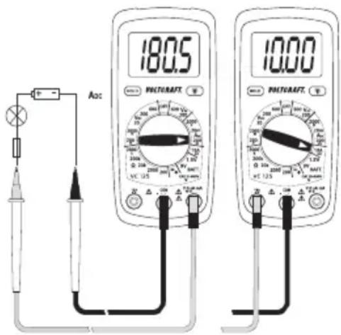
c) Direct Current Measuring "A DC"

The maximum permissible voltage in the measuring circuit against ground potential must not exceed 600V in CAT II and III.
Current measurement always takes place in series with the consumer. Before connecting the meter, the circuit must be powered down. After the end of measuring, power down the circuit before removing the measuring lines. This prevents the occurrence of light arcs.
Current measurements >5 A must only be performed for max. 30 seconds and with measuring breaks of 15 minutes.
Proceed as follows to measure direct voltages (A DC 200 mA:
- Switch on the DMM by the dial switch (3) and select the measuring range "10 A".
- Plug the red measuring line into the 10A measuring jack (4) and the black measuring line into the COM measuring jack (5).
- Connect the two measuring prods in series with the consumer. The red measuring prod indicates the positive pole, the black measuring prod the negative pole. Switch on the measuring circuit.
- The measured value is indicated on the display.

When a minus “-” appears in front of the measured value when measuring direct current, the current has the opposite direction (or the measuring lines have been swapped).
- Power down the measuring circuit after the end of measuring and remove the measuring prods from the measured object. Switch off the device. Turn the dial switch to "OFF".
d) Direct Current Measuring "mA/μA DC"

The maximum permissible voltage in the measuring circuit against ground potential must not exceed 600V in CAT II and III.
Current measurement always takes place in series with the consumer. Before connecting the meter, the circuit must be powered down. After the end of measuring, power down the circuit before removing the measuring lines. This prevents the occurrence of light arcs.
The internal resistance of the meter causes a low voltage drop in the measuring circuit (max. 200mV ) because of the integrated fuse in the mA measuring range. However, this is usually negligible.
Proceed as follows to measure direct currents (mA / A DC 200 mA:
- Switch on the DMM by the dial switch (3) and select the corresponding measuring range "mA/μA".
- Plug the red measuring line into the mA measuring jack (6) and the black measuring line into the COM measuring jack (5).
- Connect the two measuring prods in series with the consumer. The red measuring prod indicates the positive pole, the black measuring prod the negative pole. Switch on the measuring circuit.
- The measured value is indicated on the display.

When a minus “-” appears in front of the measured value when measuring direct current, the current has the opposite direction (or the measuring lines have been swapped).
- Power down the measuring circuit after the end of measuring and remove the measuring prods from the measured object. Switch off the device. Turn the dial switch to "OFF".
e) Impedance Measuring

Make sure that all circuit parts, circuits and components and other objects of measurement are disconnected from the voltage and discharged.
Proceed as follows to measure impedance:
- Switch on the DMM and select the respective measuring range / k
- Plug the red measuring line into the measuring jack (6) and the black measuring line into the COM measuring jack (5).
- Check the measuring lines for continuity by connecting the two measuring prods. The impedance value must be approximately 0 - 1.5 Ohm (inherent impedance of the measuring lines).
- Now connect the two measuring prods to the object to be measured. As long as the object to be measured is not high-impedance or interrupted, the measured value will be indicated on the display. Wait until the displayed value has stabilised. With impedances of >1 MOhm, this may take a few seconds.
- Once "OL" (= overflow) appears on the display, you have exceeded the measuring range or the measuring circuit is interrupted.
- Remove the measuring lines from the object to be measured after completion of the measurement and switch off the DMM.


If you carry out a resistance measurement, make sure that the measuring points you touch with the measuring prods are free from dirt, oil, solderable lacquer or similar. Such circumstances can falsify the measured result.
f) Acoustic Continuity Test

Make sure that all circuit parts, circuits and components and other objects of measurement are disconnected from the voltage and discharged.
- Turn the DMM on and select measuring function
- Plug the red measuring line into the V measuring jack (6) and the black measuring line into the COM measuring jack (5).
- A continuity value of less than approx. 30 Ohm is identified as continuity; in this case a beep sounds. The display is not relevant in this test.
- Once "OL" (= overflow) appears on the display, you have exceeded the measuring range or the measuring circuit is interrupted.
- Remove the measuring lines from the object to be measured after completion of the measurement and switch off the DMM.
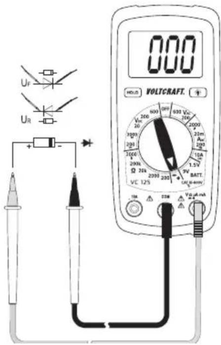
g) Diode Test

Make sure that all circuit parts, circuits and components and other objects of measurement are disconnected from the voltage and discharged.
- Turn the DMM on and select measuring function
- Plug the red measuring line into the V measuring jack (6) and the black measuring line into the COM measuring jack (5).
- Check the measuring lines for continuity by connecting the two measuring prods. The value must be approximately 000. The DMM emits a beet that is not relevant for the diode test.
- Connect the two measuring prods with the object to be measured (diode).
- The display shows the continuity voltage "UF" in milli volt (mV). When "OL" appears, the diode is measured in reverse direction (UR) or the diode is faulty (interruption). Perform a counter-pole measurement to check. At a continuity voltage of approx. < 30mV , a beep sounds. However, this is not relevant.
- Remove the measuring lines from the object to be measured after completion of the measurement and switch off the DMM.
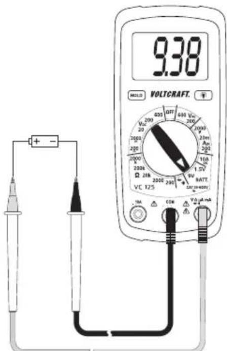
h) Battery Test
The battery test permits review of the terminal voltage of 9V block batteries and 1.5V round cell batteries. When testing, the battery is charged with a low load current that leads to an indicative test result.
- Switch on the DMM and select the respective measuring range "BATT."
- Plug the red measuring line into the V measuring jack (6) and the black measuring line into the COM measuring jack (5).
- Connect the two measuring prods with the object to be measured (battery).
- The display shows the terminal voltage of the battery under load conditions in volt.
- Remove the measuring lines from the object to be measured after completion of the measurement and switch off the DMM.
9. ADDITIONAL FUNCTIONS
a) HOLD Function
The HOLD function keeps the currently indicated measured value in the displays to allow you to read or record it easily.

If you test live wires, make sure that this function is deactivated before the measurement starts. Otherwise, the measurement will be incorrect!
Also observe that the HOLD button was not pushed at the beginning of the measurement (display with the HOLD button pushed: "HOLD"). If the HOLD button is pushed at commencement of measuring, no measured value is displayed!
Push the button "HOLD" (2) to activate the hold function. The button latches and the display shows "HOLD".
Push the button "HOLD" to deactivate the HOLD function. The display "HOLD" goes out.
b) Display Lighting
With the DMM on, the lighting button with latching function (9) switches the display lighting on and off. Every push will switch the lighting on or off. The lighting only remains on until the function is deactivated via the lighting button (9) or the dial switch (position "OFF").
10. CLEANING AND MAINTENANCE
a) General Information
To ensure accuracy of the multimeter over an extended period of time, it should be calibrated once a year.
Apart from occasional cleaning and battery and fuse replacements, the meter requires no servicing.
Notes on replacing the fuses and battery are provided below.

Regularly check the technical safety of the device and measuring lines, e.g. check for damage to the casing or squeezing, etc.
b) Cleaning
Always observe the following safety information before cleaning the device:

Live components may be exposed if covers are opened or parts are removed (unless this can be done without tools).
The connected lines must be disconnected from the meter and all measuring objects before the device is cleaned or repaired. Switch off the DMM.
Do not use any abrasive cleaning agents or petrol, alcohol or the like to clean the product. They will damage the surface of the meter. Furthermore, the fumes are hazardous to your health and explosive. Also do not use any sharp-edged tools, screwdrivers, metal brushes, etc. for cleaning.
Use a clean, lint-free, antistatic, slightly damp cloth for cleaning the device or the display and the measuring lines. Allow the product to dry completely before you use it again to conduct measurements.
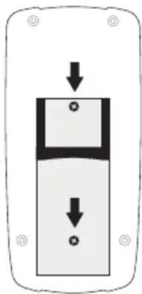
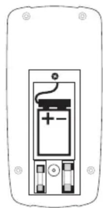
c) Inserting and changing the batteries
Operation of the meter requires a 9 V block battery (e.g. 6F22 or same build). You need to insert a new, charged battery before initial operation or when the battery change symbol appears on the display.
Proceed as follows to insert or change the batteries:
- Disconnect the connected measuring lines from the measuring circuit and the meter. Switch off the DMM.
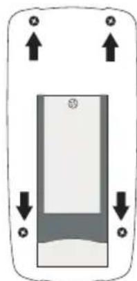
- Fold up the rear setup bracket and loosen the two rear screws at the battery compartment lid (8) with a suitable Phillips screwdriver. Remove the battery compartment lid from the device.
- Replace the flat battery with a new one of the same type. Connect the new battery with the battery clip in the correct polarity and insert the battery into the compartment. Observe the polarity as indicated in the battery compartment.
- Close the casing carefully again.

Never operate the meter when it is open. !DANGER TO LIFE!
leave flat batteries in the meter. Even batteries protected against leaking can corrode and thus release chemicals which may be detrimental to your health or destroy the device.
Do not leave batteries lying around carelessly. They could be swallowed by children or pets. If swallowed, consult a doctor immediately.
Remove the battery if the device is not used for extended periods of time to prevent leaking.
Leaking or damaged batteries may cause alkali burns if they come in contact with the skin. Therefore, use suitable protective gloves.
Make sure that the batteries are not short-circuited. Do not throw batteries into the fire.
Batteries must not be recharged or dismantled. There is a risk of fire and explosion.

You can order suitable alkaline batteries stating the following item no.:
item no. 65 25 09 (please order one).
Only use alkaline batteries, as they are powerful and have a long service life.
d) Fuse Change
The current measuring ranges are protected against overload with high-performance fuses. If no measurements in the current measuring range are possible anymore, the fuses are probably defective and need to be replaced.

Always observe the safety provisions during use changes!
Ensure that only fuses of the indicated type and rated current must be used as spares. Use of wrong or patched-up fuses or bridging of the fuse holder is not permitted and may cause fire.
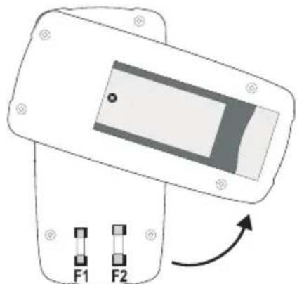
Proceed as follows for fuse replacement:
-
Disconnect the connected measuring lines from the measuring circuit and the meter. Switch off the DMM.
-
Loosen the four rear housing screws with a matching Phillips screwdriver. Carefully loosen the two housing halves from each other and turn away the rear as shown. Observe the battery cable
- Replace the defective fuse with a new fuse of the same type and rated current.
FUSE1:FF200mA600V5mm×20mm
FUSE2:F10A 600V5mm×20mm
However, always observe the information at the device or the values of the fuse used.
- Close the casing carefully again.

Never operate the meter when it is open. !DANGER TO LIFE!
11. DISPOSAL
Old electronic devices are recyclable and should not be disposed of in household waste. At the end of its service life, dispose of the product at the community collection point according to the relevant statutory regulations. It is prohibited to dispose of the device in household waste.
Disposal of used batteries!
You as the end user are required by law (Battery Ordinance) to return all used batteries/rechargeable batteries. Disposing of them in household waste is prohibited!

Batteries/rechargeable batteries containing harmful substances are marked with the following symbols, which point out that they are not allowed to be disposed of in the domestic refuse. The descriptions for the respective heavy metals are: Cd = cadmium, Hg = mercury, Pub = lead. You may return used batteries/rechargeable batteries free of charge at the official collection points of your community, in our stores, or wherever batteries/rechargeable batteries are sold!
You thus fulfil the legal requirements and make your contribution to protecting the environment!
12. TROUBLESHOOTING
In purchasing the DMM, you have acquired a product designed to the state of the art and operationally reliable.
Nevertheless, problems or errors may occur.
For this reason, the following is a description of how you can easily remove possible malfunctions yourself:

Always observe the safety provisions during use changes!
| Error Possible cause Remedy | ||
| The multimeter does not work. Are the batteries dead? Check the status. Replace the battery. | ||
| No measured value change | Is the wrong measuring function activated (AC/DC)? | Check the measuring range (AC/DC) and switch the function if required. |
| Are the measuring lines reliably inserted in the measuring jacks? | Check the proper fit of the measuring lines | |
| Is the Hold function activated (display "HOLD")? | Push the button "HOLD" to deactivate this function. | |
| Fuse in the current measuring range defective | Check the corresponding fuse. | |

Repairs other than those described above should only be carried out by an authorised specialist. If you have any questions about handling the meter, our technical support is available.
13. TECHNICAL DATA
Display. 2000 counts (characters)
Measuring rate...........................approx. 2 measuring operations/second
Measuring method V/AC .arithmetic average
Measuring line length .each approx. 90 cm
Measuring impedance. >1 MΩ (V-range)
Measuring socket distance 19 mm
Voltage supply 9 V block batteries (NEDA 1604, 6F22 or same build)
Operating conditions .0 to 50^ (< 70%) rF
Operating height max. 2000 m
Storage conditions -20 ^ C to +60^ (< 80%) rF
Weight approx. 210 g
Dimensions (LxWxH) 138 x 68 x 37 (mm)
Measuring category... .CAT III 600 V
Degree of contamination 2
Measurement tolerances
Statement of accuracy in ± (% of reading + display error in counts (= number of smallest points)). The accuracy is valid for one year at a temperature of +23^ ± 5^ , and at a relative humidity of less than 75% , non-condensing.
Direct voltage (V DC)
| Range Accuracy Resolution | ||
| 200.0 mV | ±(0.7% + 3) | 0.1 mV |
| 2000 mV 1 mV | ||
| 20.00 V 0.01 V | ||
| 200.0 V | ±(1.0% + 3) | 0.1 V |
| 600 V 1 V | ||
| Overload protection 600 V; Impedance: >1 MΩ | ||
Alternating voltage (A DC)
| Range Accuracy (at 50/60) | Hz) Resolution | |
| 200 V | ±(1.5% + 12) | 0.1 V |
| 600 V 1 V | ||
| Frequency range 45 – 450 Hz; Overload protection 600 V; Impedance: >1 MΩ | ||
Direct current
| Range Accuracy Resolution | ||
| 2000 μA | ±(1.5% + 3) | 1 μA |
| 20 mA 0.01 mA | ||
| 200 mA 0.1 mA | ||
| 10 A ±(2.5% + 2) 0.01 A | ||
| Overload protection 600 V; high-performance ceramic fuses: | ||
Resistance
| Range Accuracy Resolution | ||
| 200.0 Ω | ±(1.2% + 4) | 0.1 Ω |
| 2000 Ω 1 Ω | ||
| 20.00 kΩ 0.01 kΩ | ||
| 200.0 kΩ 0.1 kΩ | ||
| 2000 kΩ ±(1.5% + 2) 1 kΩ | ||
| Overload protection 250 V; max. 15 s. | ||
Battery test
| Range Accuracy Resolution | ||
| 1.5 V | ±(1.5% + 3) | 0.001 V |
| 9 V 0.01 V | ||
| Load current: 1.5 V-range: 100 mA 9 V-range: 6 mA | ||
Diode test
| Test voltage Resolution | |
| approx. 2.8 V 1 mV | |
| Overload protection: 250 V max. 15 s; test current max. 1 mA | |
Acoustic continuity tester
Overload protection: 250V max. 15 s; <30 permanent sound

Do not exceed the maximum permitted input values. Do not touch any circuits or parts of circuits if they may be subject to voltages higher than 33 V/ACrms or 70 V/DC! Danger to life!
Page
- INTRODUCTION 46
- UTILISATION CONFORME 47
- ÉléMENTS DE COMMANDE 48
- ETENDUE DE LA LIVRAISON 48
- CONSIGNES DE SECURITE 48
6.DESCRIPTION DU PRODUIT 51 - INFORMATIONS ET SYMBOLES SUR L'ECRAN 52
- MODE DE MESURE 53
France (email): technique@conrad-france.fr
Suisse:
www.conrad.ch
www.biz-conrad.ch
2. UTILISATION CONFORME
6.DESCRIPTION DU PRODUIT
Tension alternative (V AC)
6.PRODUCTOMSCHRIJVING
Copyright 2015 by Conrad Electronic SE.
GB Legal Notice
This is a publication by Conrad Electronic SE, Klaus-Conrad-Str. 1, D-92240 Hirschau (www.conrad.com).
All rights including translation reserved. Reproduction by any method, e.g. photocopy, microfilming, or the capture in electronic data processing systems require the prior written approval by the editor. Reprinting, also in part, is prohibited. This publication represent the technical status at the time of printing.
Copyright 2015 by Conrad Electronic SE.
F Information legales
Copyright 2015 by Conrad Electronic SE.
NL Colofon
Copyright 2015 by Conrad Electronic SE.
V4_0916_02/VTP