Kronos 400T W - Welding machine GYS - Free user manual and instructions
Find the device manual for free Kronos 400T W GYS in PDF.

| Product type | Professional three-phase welding machine |
| Brand | GYS |
| Model | Kronos 400T W |
| Welding processes | MIG/MAG (GMAW/FCAW), TIG (GTAW), MMA (SMAW) |
| Power supply | Three-phase 400 V ±15%, 50-60 Hz, 32 A plug type EN 60309-1 |
| Maximum power | Welding current up to 400 A (depending on cycle) |
| Duty cycle | At 40°C, on a 10 min cycle (details in manual) |
| Supported wire diameters | Steel/Stainless: ∅ 0.6 to 1.2 mm; Aluminum: ∅ 0.8 to 1.2 mm; Flux-cored: ∅ 0.9 to 1.6 mm |
| Accepted spools | ∅ 200 mm and 300 mm |
| Cooling | Integrated water cooling (cooling unit), with specific liquid ref. 052246 |
| Liquid tank capacity | 5.5 liters |
| Protection | IP23S (protection against inclined rain and solids >12.5 mm) |
| User interface | Digital screen with knobs, Easy and Expert modes, gas flow control, purge, calibration |
| Special functions | Synergic, Hot Start, Arc Force, Anti-Stick, pulsing, spot welding, QuickLoad (20 jobs), traceability |
| Connectivity | USB port for software update and configuration transfer |
| Dimensions (approx.) | Height ~900 mm, width ~500 mm, depth ~800 mm (estimate) |
| Weight (approx.) | ~100 kg (estimate with cooling unit) |
| Operating temperature | -10°C to +40°C |
| Storage temperature | -20°C to +55°C |
| Routine maintenance | Regular dusting, coolant change every 12 months, check connections |
| Safety | Automatic shutdown on overheating, thermal protection, hood locking, emergency stop (switch) |
| Spare parts | Rollers, torches, contact tips, nozzles, liners, coolant, fuses, cables (accessories optional) |
| Repairability | Maintenance by qualified personnel; software update via USB; cable calibration possible |
Frequently Asked Questions - Kronos 400T W GYS
User questions about Kronos 400T W GYS
0 question about this device. Answer the ones you know or ask your own.
Ask a new question about this device
Download the instructions for your Welding machine in PDF format for free! Find your manual Kronos 400T W - GYS and take your electronic device back in hand. On this page are published all the documents necessary for the use of your device. Kronos 400T W by GYS.
USER MANUAL Kronos 400T W GYS
natural_image
Line drawing of a mechanical testing device with wheels and control panel (no text or symbols)| FR | 02-05 / 06-20 / 79-92 |
| EN | 02-05 / 21-34 / 79-92 |
| DE | 02-05 / 35-49 / 79-92 |
| NL | 02-05 / 50-64 / 79-92 |
| IT | 02-05 / 65-78 / 79-92 |
natural_image
Line drawing of a mechanical testing device with wheels and control panel (no text or symbols)KRONOS
400T DUO / 400T W
natural_image
Technical line drawing of a mechanical device with wheels and a central rotating wheel (no text or symbols)
natural_image
Technical line drawing of a mechanical device with wheels and ventilation grilles (no text or symbols)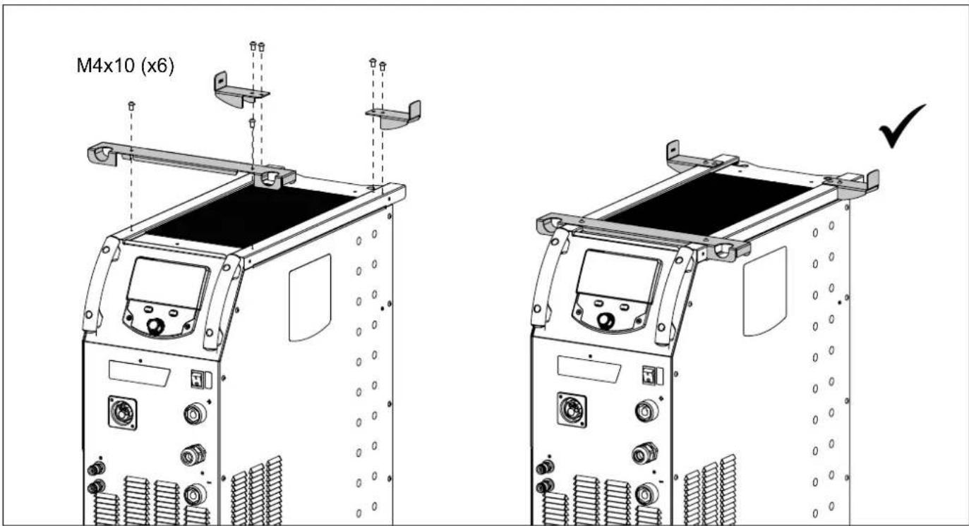
text_image
M4x10 (x6)SUPPORT BOUTEILLE / BOTTLE SUPPORT / FLASCHENHALTER / PORTABOTELLAS / FLESSENHOU-DER / PORTABOTTIGLIE
text_image
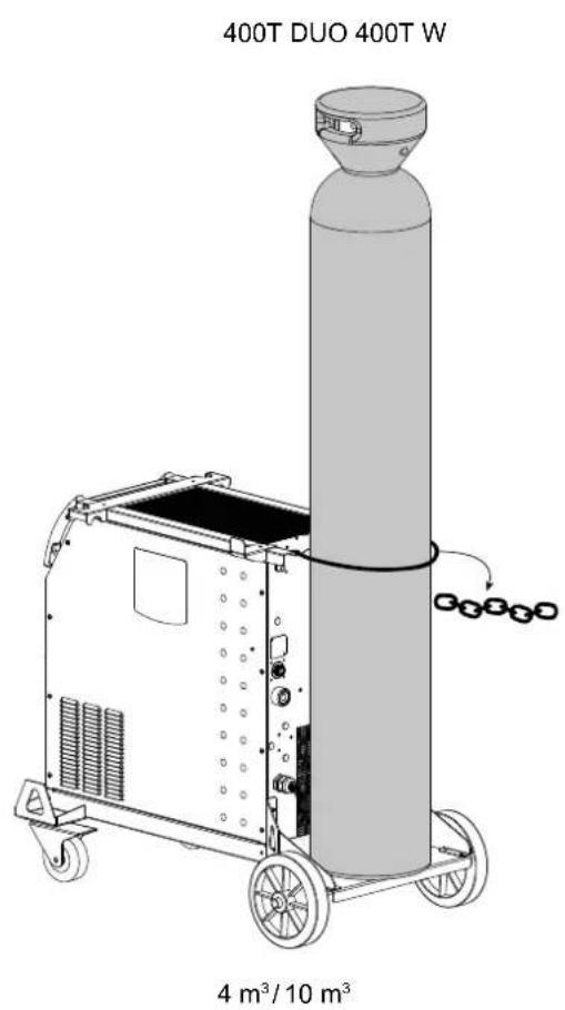
400T DUO 400T W 4 m³/10 m³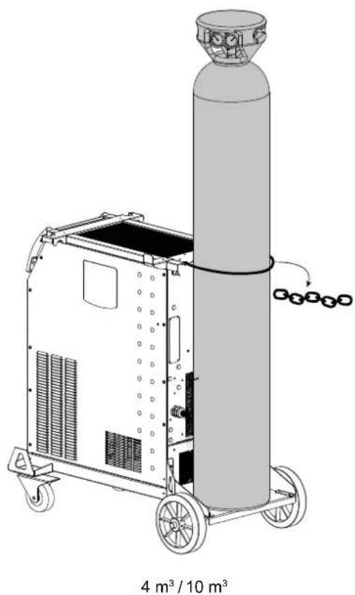
natural_image
Technical line drawing of a cylindrical industrial machine with wheels and a conical top, labeled '4 m³ / 10 m³' at the bottom (no text or symbols on the diagram itself)RACCORD GAZ / GAS FITTINGS / GASANSCHLUSS / CONEXIÓN DE GAS / ГАЗОВОЕ СОЕДИНЕНИЕ / GAS AANSLUITING / COLLEGAMENTO GAS
| 400T W | 400T DUO | 400T DUO + WF 35 (option) | |
| 1 x 2 m | 400T DUO | ||
| Faisceau en optionOptional connection cable | WF 35(option) | ||
| 1 x 1 m | 1 x 2 m | ou / or / oder / o | WF 35(option) |
| 2 | 400T DUO | ||
| 1 | 2 m | ||
| 1 | |||
| 2 Faisceau / Connection cable | |||
PROCÉDURE DE MISE À JOUR / UPDATE PROCEDURE
Clé USB non fournie / USB key not included.
text_image
Technical diagram of a mechanical device with numbered parts for identification and assembly reference.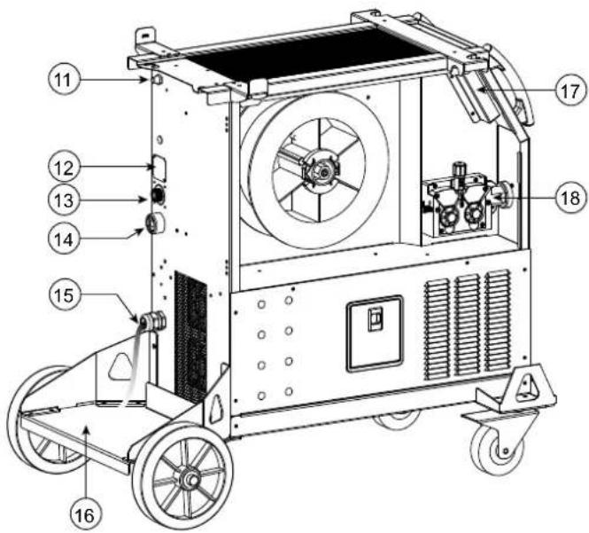
text_image
Technical diagram of a mechanical device with numbered components for identification400T W
text_image
Technical diagram of a mechanical device with numbered components for identification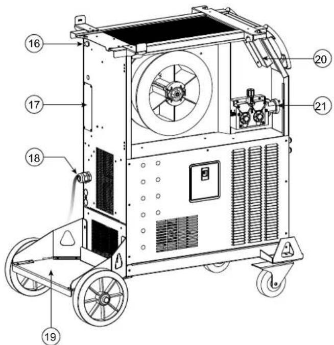
text_image
Technical diagram of a mechanical device with numbered components for identification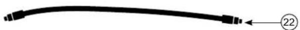
AVERTISSEMENTS - RÈGLES DE SÉCURITÉ
CONSIGNE GÉNÉRALE
INSTALLATION – FONCTIONNEMENT PRODUIT
INTERFACE HOMME-MACHINE (IHM)

IHM
text_image
Technical diagram of a mechanical device with labeled parts a and bnatural_image
Technical line drawing of a mechanical component with labeled parts (a, 1, 2, 3, 4, 5), no readable text or symbols beyond part numbers.natural_image
Line drawing of a portable industrial machine with control panel and wheels (no text or symbols)natural_image
Line drawing of a mechanical device with wheels and control panel (no text or symbols)text_image
Bouton principal T1 T2natural_image
Technical line drawing of a mechanical device mounted on a base panel (no text or symbols visible)ANOMALIES, CAUSES, REMÈDES
CONDITIONS DE GARANTIE
These instructions must be read and fully understood before use. Do not carry out any alterations or maintenance work that is not directly specified in this manual.
The manufacturer shall not be liable for any damage to persons or property resulting from use not in accordance with the instructions in this manual. In case of problems or queries, please consult a qualified tradesperson to correctly install the product.
ENVIRONMENT
This equipment should only be used for welding operations performed within the limits indicated on the information panel and/or in this manual. These safety guidelines must be observed. The manufacturer cannot be held responsible in the event of improper or dangerous use.
The machine must be set up somewhere free from dust, acid, flammable gases or any other corrosive substances. This also applies to the machine's storage. Ensure good air circulation when in use.
Temperature range:
Use between -10 and +40°C (+14 and +104°F).
Store between -20 and +55°C (-4 and 131°F).
Air humidity:
Lower than or equal to 50% at 40°C (104°F).
Lower than or equal to 90% at 20°C (68°F).
Altitude:
Up to 1000m above sea level (3,280 feet).
PROTECTING YOURSELF AND OTHERS
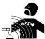
Arc welding can be dangerous and cause serious injury or death.
Welding exposes people to a dangerous source of heat, light radiation from the arc, electromagnetic fields (caution to those using pacemakers) and risk of electrocution, as well as noise and fumes.
To protect yourself and others, please observe the following safety instructions:

To protect yourself from burns and radiation, wear insulating, dry and fireproof clothing without lapels. Ensure the clothing is in good condition and that covers the whole body.

Wear protective gloves which provide electrical and thermal insulation.

Use welding protection and/or a welding helmet with a sufficient level of protection (depending on the specific use). Protect your eyes during cleaning procedures. Contact lenses are specifically forbidden.
It may be necessary to section off the welding area with fireproof curtains to protect the area from arc radiation and hot spatter. Inform people in the welding area not to stare at the arc rays or molten parts and to wear appropriate clothing for protection.

Wear noise protection headphones if the welding process becomes louder than the permissible limit (this is also applicable to anyone else in the welding area).
Keep hands, hair and clothing away from moving parts (the ventilation fan, for example).
Never remove the cooling unit housing protections when the welding power source is live, the manufacturer cannot be held responsible in the event of an accident.
Newly welded parts are hot and can cause burns when handled. When maintenance work is carried out on the torch or electrode holder, ensure that it is sufficiently cold by waiting at least 10 minutes before carrying out any work. The cooling unit must be switched on when using a water-cooled torch to ensure that the liquid cannot cause burns.
It is important to secure the working area before leaving it, in order to protect people and property.
WELDING FUMES AND GAS

The fumes, gases and dusts emitted by welding are harmful to health. Sufficient ventilation must be provided and an additional air supply may be required. An air-fed mask could be a solution in situations where there is inadequate ventilation.
Check the extraction system's performance against the relevant safety standards.
Caution: Welding in confined spaces requires safety monitoring from a safe distance. In addition, the welding of certain materials containing lead, cadmium, zinc, mercury or even beryllium can be particularly harmful. Remove any grease from the parts before welding.
Cylinders should be stored in open or well-ventilated areas. They should be stored in an upright position and kept on a stand or trolley.
Welding should not be carried out near grease or paint.
RISK OF FIRES AND EXPLOSIONS

Fully shield the welding area, flammable materials should be kept at least 11 metres away.
Fire fighting equipment should be kept close to wherever the welding activities are being undertaken.
Beware the expulsion of hot spatter or sparks, even through cracks, which can cause fires or explosions.
Keep people, flammable objects and pressurised containers at a safe distance.
Welding in closed containers or tubes is to be avoided. If the containers or tubes are open, they must be emptied of all flammable or explosive materials (oil, fuel, gas residues, etc.).
Grinding work must not be directed towards the source of the welding current or towards any flammable materials.
GAS CYLINDERS
Gas escaping from cylinders can cause suffocation if there is too high a concentration of it in the welding area (ensure good ventilation).
The machine must be transported in complete safety: gas cylinders must be closed and the welding power source turned off. They should be stored upright and supported to limit the risk of falling.
Close the cylinder between uses. Beware of temperature variations and exposure to the sun.
The cylinder must not come into contact with flames, arcs, torches, earth clamps or any other sources of heat or ignition.
Be sure to keep it away from electrical and welding circuits. Never weld a pressurised cylinder.
When opening the cylinder valve, keep your head away from the valve and ensure that the gas being used is suitable for the welding process.
ELECTRICAL SAFETY

The electrical network used must be earthed. Use the recommended fuse size from the rating plate.
An electric shock can be the source of a serious accident, whether directly or indirectly, or even death.
Never touch live parts connected to the live current, either inside or outside the power source casing unit (torches, clamps, cables, electrodes), as these items are connected to the welding circuit.
Before opening the welding machine's power source, disconnect it from the mains and wait two minutes to ensure that all the capacitors have fully discharged.
Do not touch the torch or the electrode holder and the earth clamp at the same time.
If the cables or torches become damaged, they must be replaced by a qualified and authorised person. Measure the cable cross-section according to the intended application. Always use dry and in-fact clothing to insulate yourself from the welding circuit. Alongside this, wear well-insulated footwear in all working environments.
EMC CLASSIFICATION

This Class A device is not intended for use in a residential environment where power is provided by the public low-voltage local supply network. Ensuring electromagnetic compatibility may be difficult at these sites due to conducted, as well as radiated, radio frequency interference.
Provided that the impedance of the public low-voltage supply network is less than Zmax = 0.29 Ohms at the common coupling point, this equipment complies with IEC 61000-3-11 and can be connected to public low-voltage electrical supply. It is the responsibility of the fitter or operator of the equipment to ensure, by consulting the electricity distribution network provider if necessary, that the network impedance complies with impedance restrictions.
This equipment complies with the IEC 61000-3-12 standard.
ELECTROMAGNETIC INTERFERENCES
An electric current passing through any conductor produces localised electric and magnetic fields (EMF). The welding current produces an electromagnetic field around the welding circuit and the welding equipment.
Electromagnetic fields (EMFs) can interfere with some medical devices, for example pacemakers. Protective measures must be taken for people with medical implants. For example, restricted access for onlookers or an individual risk assessment for welders.
All welders should use the following guidelines to minimise exposure to the welding circuit's electromagnetic fields:
- position the welding cables together - securing them with a clamp if possible;
- position yourself (head and body) as far away from the welding circuit as possible,
-
never wrap the welding cables around your body,
-
do not position yourself between the welding cables. and keep both welding cables on your same side,
- connect the return cable to the workpiece, as close as possible to the area to be welded,
- do not work next to, sit or lean on the source of the welding current,
- do not transport the welding power source or wire feeder while welding.

Pacemaker users should consult a doctor before using this equipment.
Exposure to electromagnetic fields during welding may have other health effects that are not yet known.
RECOMMENDATIONS FOR ASSESSING THE WELDING AREA AND EQUIPMENT
General Information
It is the user's responsibility to install and use the arc welding equipment according to the manufacturer's instructions. If electromagnetic disturbances are detected, it is the user's responsibility to resolve the situation using the manufacturer's technical support. In some cases, this corrective action may be as simple as earthing the welding circuit. In other cases, it may be necessary to construct an electromagnetic shield around the welding current source and around the entire workpiece by setting up input filters. In any case, electromagnetic interference should be reduced until it is no longer an inconvenience.
Assessing the welding area
Before installing arc welding equipment, the user should assess the potential electromagnetic problems in the surrounding area. The following should be taken into account:
a) the presence of power, control, signal and telephone cables above, below and next to the arc welding equipment,
b) radio and television receivers and transmitters,
c) computers and other control equipment,
d) critical safety equipment, e.g. the protection of industrial equipment,
e) the health of nearby persons, e.g. those using of pacemakers or hearing aids,
f) the equipment used for calibrating or measuring,
g) the protection of other surrounding equipment.
The operator has to ensure that the devices and equipment used in the same area are compatible with each other. This may require further protective measures;
h) the time of day when welding or other operations are to be carried out.
The size of the surrounding area to be taken into account will depend on the building's structure and the other activities taking place there. The surrounding area may extend beyond the boundaries of the premises.
Assessment of the welding equipment
In addition to the assessment of the surrounding area, the arc welding equipment's assessment can be used to identify and resolve cases of interference. It is appropriate that the assessment of any emissions should include in situ procedures as specified in Article 10 of CISPR 11. In situ measurements can also be used to confirm the effectiveness of mitigation measures.
GUIDELINES ON HOW TO REDUCE ELECTROMAGNETIC EMISSIONS
a. The mains power grid: Arc welding equipment should be connected to the mains power grid according to the manufacturer's recommendations. If any interference occurs, it may be necessary to take additional precautionary measures such as filtering the mains power supply. Consider protecting the power cables of permanently installed arc welding equipment within a metal pipe or a similar casing. The power cable should be protected along its entire length. The shield should be connected to the welding power source to ensure that there is good electrical contact between the conduit and the welding power source enclosure.
b. The maintenance of arc welding equipment: Arc welding equipment should be subject to routine maintenance as recommended by the manufacturer. All access points, service openings and bonnets should be closed and properly locked when the arc welding equipment is in use. The arc welding equipment should not be modified in any way, except for those modifications and adjustments mentioned in the manufacturer's instructions. The spark gap of arc starters and stabilisers should be adjusted and maintained according to the manufacturer's recommendations.
c. Welding cables: Cables should be as short as possible, placed close together either near or on the ground.
d. Equipotential bonding: Consideration should be given to linking all metal objects in the surrounding area. However, metal objects connected to the workpiece increase the risk of electric shocks to the user if they touch both these metal parts and the electrode. It is necessary to insulate the operator from such metal objects.
e. Earthing the workpiece: In cases where the part to be welded is unearthed for electrical safety reasons or due to its size and location, such as ship hulls or structural steel buildings, an earthed connection can reduce emissions in some cases, although not always. Care should be taken to avoid the earthing of parts which could increase the risk of injury to users or damage to other electrical equipment. If necessary, the workpiece's connection should be earthed directly, but in some countries where a direct connection is not allowed, the connection should be made with a suitable capacitor chosen according to national regulations.
f. Protection and protective casing: The selective protection and encasing of other cables and equipment in the surrounding area may limit interference problems. The safeguarding of the entire welding area may be considered for special applications.
THE TRANSPORTING AND MOVING OF THE MACHINE'S POWER SOURCE
Do not use the cables or torch to move the welding power source. It should be moved in an upright position. Do not carry or transport the power source overhead of people or objects.
Never lift a gas cylinder and the welding power source at the same time. Their transportation requirements are different.
It is advisable to remove the wire spool before lifting or transporting the welding power source.
SETTING UP THE EQUIPMENT
- Place the welding power source on a floor with a maximum inclination of 10^ .
- Provide sufficient space to ventilate the welding power source and access the controls.
- Do not use in an area with conductive metal dust.
- The welding power source should be protected from heavy rain and not exposed to direct sunlight.
• The machine is IP23S rated, meaning: - its dangerous parts are protected from being entered by objects greater than 12.5 mm and,
- it is protected against rain falling at an angle of up to 60° from vertical, providing that any moving parts (fan) are stationary.
This product can therefore be stored outdoors in accordance with the IP23 protection rating.

Stray welding currents can destroy earthing conductors, damage electrical equipment and devices and cause component parts to overheat leading to fires.
- All welding connections must be firmly secured and regularly checked!
- Make sure that the item's attachment is firm and secure, without any electrical problems!
- Join together or suspend any electrically conductive parts of the welding source such as the frame, trolley and lifting systems so that they are insulated!
- Do not place other equipment such as drills or grinding devices etc. on the welding source, trolley, or lifting systems unless they are insulated!
- Always place welding torches or electrode holders on an insulated surface when not in use!
The power cables, extensions and welding cables must be fully uncoiled to prevent overheating.
The manufacturer assumes no responsibility for damage to persons or objects caused by improper and dangerous use of this equipment.
MAINTENANCE / RECOMMENDATIONS

□ Maintenance should only be carried out by a qualified person. Annual maintenance is recommended.
☐ Switch off the power supply by pulling the plug and wait two minutes before working on the equipment.. Inside the machine, the voltages and currents are high and dangerous.
- Regularly remove the cover and blow out any dust. Take advantage of the opportunity to have the electrical connections checked with an insulated tool by a qualified professional.
Regularly check the condition of the power cable. If the power cable is damaged, it must be replaced by the manufacturer, the after sales service team or an equally qualified person to avoid any danger.
- Leave the welding power source vents free for air intake and outflow.
- Do not use this welding power source for thawing pipes, recharging batteries/storage batteries or starter motors.

400T-W :
The coolant should be changed every 12 months to prevent residue from clogging the torch's cooling system. Any leaks or product residues found after use, must be treated in an appropriate treatment plant. If possible, the product should be recycled. It is forbidden to drain the used material into waterways, pits or drainage systems. Diluted fluid should not be emptied into the sewage system, except where allowed under local regulations.
INSTALLATION - USING THE PRODUCT
Only experienced personnel, authorised by the manufacturer, may carry out the machine's set-up. During set-up, ensure that the power source is unplugged from the mains. Series or parallel power source connections are not allowed. It is recommended to use the welding cables supplied with the unit in order to obtain the best possible product performance.
DESCRIPTION
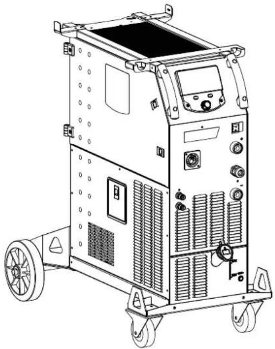
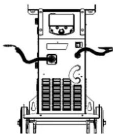
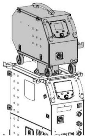
This machine is a three-phase power source for semi-automatic, software-supported welding (MIG or MAG), coated electrode welding (MMA) and refractory electrode welding (TIG). It accepts 200 and 300 mm diameter wire spools.
DESCRIPTION OF THE EQUIPMENT (II)
400T-DUO
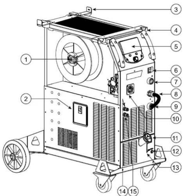
1- Reel support ∅ 200/300 mm 10- Euro connector (torche)
2- Accessory box hatch 11- Gas connector
3- Cable support 12- Cover option
4- Torch support 13- Connector for external wire feeder control
5- HMI (Human Machine Interface) 14- Positive polarity socket
6- START/STOP switch 15- Mains cable (5 m)
7- Positive polarity socket 16- Bottle holder 4m3 or 10m3
8- Polarity reversal cable 17- USB hatch
9- Negative polarity socket 18- Wire-feed motor
400T-W
1- Reel support ∅ 200/300 mm 12- Fuse for cooling unit
2- Accessory box hatch 13- Tank level indicator
3- Cable support 14- Liquid coolant outlet (Blue)
4- Torch support 15- Liquid coolant outlet (Red)
5- HMI (Human Machine Interface) 16- Gas connector
6- START/STOP switch 17- Cover option
7- Positive polarity socket 18- Mains cable (5 m)
8- Polarity reversal cable 19- Bottle holder 4m3 or 10m3
9- Negative polarity socket 20- USB hatch
10- Euro connector (torche)
11- Filling cap
21- Wire-feed motor
22- Priming hose
21- Wire-feed motor
22- Priming hose
HUMAN-MACHINE INTERFACE (HMI)

HMI
Please read the Interface User Guide (HMI) which forms part of the complete product literature.
POWER SWITCH
This machine is fitted with a 32A socket type EN 60309-1 which must only be used on a three-phase 400 V (50-60 Hz) four-wire earthed electrical installation.
The absorbed effective current (I1eff) is indicated on the device for optimum operating conditions. Check that the power supply and its safeguards (fuse and/or circuit breaker) are compatible with the electric current being used. In some countries, it may be necessary to change the plug to allow the use at maximum settings.
- The power source is designed to operate at 400 V +/- 15%. The unit enters protection mode if the supply voltage is less than 330Vrms or greater than 490Vrms. (An error code will appear on the display screen).
- Starting is done by pressing the START/STOP switch (On), and stopping is done by pressing the same switch (Off). Warning! Never switch off the power supply while the unit is under load.
CONNECTING TO A POWER SOURCE
This equipment can be operated with electric generators provided that the auxiliary power supply meets the following requirements:
- The voltage must be alternating with an RMS value of 400V +/- 15% and a peak voltage of less than 700V.
- The frequency must be between 50 and 60 Hz.
It is vital to check these conditions as many generators produce high voltage peaks that can damage equipment.
USING EXTENSION LEADS
All extension leads must be of a suitable length and width that is appropriate to the equipment's voltage. Use an extension lead that complies with national safety regulations.
| Input voltage | Length - Cross-section of the extension cable (Length < 45m) |
| 400 V | 4mm^2 |
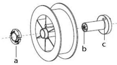
SETTING UP THE REEL

- Remove the nozzle (a) and contact tube (b) from your MIG/MAG torch.
text_image
a b cOpen the power source's hatch.
- Position the reel on its holder.
- Take into consideration the reel stands's drive lug (c). To fit a 200 mm reel, tighten the plastic reel holder (a) to the maximum.
- Adjust the brake wheel (b) to prevent the non-moving spool from tangling the wire when the welding stops. Do not over tighten as this will cause the power source to overheat.
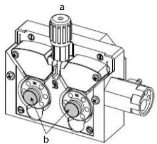
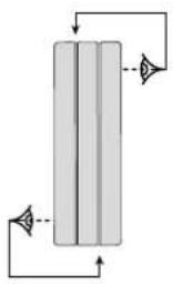
LOADING THE FILLER WIRE
text_image
a bTo change the rollers, do the following:
- Loosen the knob (a) to the maximum and lower it.
- Unlock the rollers by removing the retaining screws (b)
- Fit the appropriate drive rollers for your application and retighten the retaining screws.
The rollers supplied are double groove rollers :
- steel ∅ 1.0/1.2
natural_image
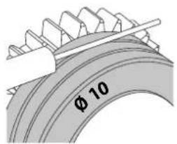
Pure diagram of a vertical cylindrical structure with directional arrows indicating flow or movement (no text or symbols)- Check the inscription on the roller to ensure that the rollers are suitable for the wire diameter and the wire material (for ∅ 1.0 wire, use the ∅ 1.0 groove).
- Use V-grooved rollers for steel and other hard wires.
- Use U-grooved rollers for aluminium and other soft, alloyed wires.
: visible inscription on the roller (example: 10 = ∅ 1.0)
→ : groove to be used
text_image
φ 10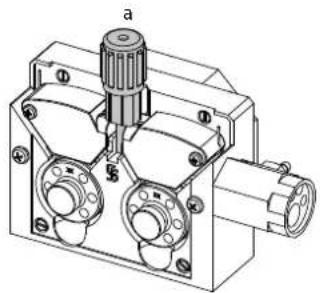
natural_image
Technical line drawing of a mechanical component with no visible text or symbolsTo install the wire, follow the steps below:
- Loosen the knob to the maximum and lower it.
- Insert the wire, then close the motor reel and tighten the knob as shown.
- Press the trigger of the torch to activate the motor, and the procedure will be displayed on the screen..

Notes:
- Too narrow a sheath can lead to unreeling issues and can lead to the overheating of the motor.
- The torch connection must also be properly tightened to prevent it from overheating.
- Ensure that neither the wire, nor the reel, touches the device's mechanism, otherwise there is a danger of short-circuiting the machine.
RISK OF INJURY FROM MOVING COMPONENTS

The reels have moving parts that can trap hands, hair, clothing or tools causing injuries!
- Do not touch rotating, moving or driving parts of the machine!
- Ensure that the housing covers or protective covers remain fully closed when in operation.
- Do not wear gloves when threading the filler wire or changing the filler-wire's spool.
COOLANT PUMP PRIMING (400T-W)
When using the product for the first time, or after completely emptying the coolant tank, the following procedure must be followed to start the circulation:
- Fill the coolant reservoir to its maximum level. The tank has a 5.5 litre capacity.
- Connect the priming hose (II-ww) to the coolant outlet connector (I-14) and place the other end in an empty container (ideally a bottle).
- Turn on the power source.
- In the «System/Cooling unit» menu, press push-button no. 2 (to start the priming procedure.
- Once the pump is primed (container is filling with coolant), stop the cooling unit by pressing one of the buttons on the HMI.
- Disconnect the priming hose and return the liquid to the cooling system: the pump is now primed.
LIQUID COOLING (400T-W)
FILLING
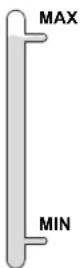
The cooling unit tank must be filled to the MAX level indicated by the gauge on the front, and must never be allowed to fall below the MIN level. A warning message will be triggered if this occurs.
It is essential to use a specific coolant for welding machines that has low electrical conductivity as well as being anti-corrosion and anti-freeze (ref. 052246).
The use of other coolants, in particular the standard automotive coolants, can lead to the accumulation of solid deposits in the cooling system through electrolysis, thus degrading the cooling system and even clogging it entirely.
This recommended MAX level is essential for optimum performance of the liquid-cooled torch.
Any damage to the machine caused by the use of a coolant other than the recommended variety will not be covered under the warranty..
USAGE
1 NEVER USE the machine's power source WITHOUT COOLING LIQUID while the pump is running.
Meet the minimum coolant level. Failure to do so may result in permanent damage to the cooling system pump.
2. Ensure that the cooling unit is switched off before disconnecting the torch's fluid inlet and/or outlet pipes. Coolant is harmful and irritates the eyes, mucous membranes and skin. Hot liquid can cause burns.
3. Danger of burns from hot liquid. Never drain the cooling unit after use. The liquid inside the machine is boiling hot, wait for it to cool before draining.
In «AUTO» mode, the cooler pump starts running when welding is started. When welding stops, the pump continues to run for a further 10 minutes. During this time, the liquid cools the welding torch bringing it back to room temperature. Leave the power source plugged in for a few minutes after welding to allow it to cool.
In the MIG-MAG process, the cooling system is activated by default (AUTO). To use an air-cooled MIG-MAG torch, it is necessary to switch the cooling system off. Please refer to the interface manual to do this.
SEMI-AUTOMATIC STEEL/STAINLESS STEEL WELDING (MAG MODE)
This machine can weld steel and stainless steel wire from 0.6 to 1.2mm (I-A). The unit is supplied with 1.0/1.2 rollers for steel or stainless steel as standard. The contact tip, the grooved roller, and the torch sheath are designed for this application.
For operation on steel, a specific welding gas (Ar+CO2) is required. The amount of CO2 may vary depending on the type of gas used. For stainless steel, use a 2% CO2 mixture. When welding with pure CO2, it is necessary to connect a gas pre-heater to the gas cylinder. For specific gas issues, please contact your gas distributor. The gas flow rate for steel is between 8 and 15 litres per minute depending on the surroundings. To check the gas flow rate on the manometer without unwinding the welding wire, press and hold push-button n°1 and follow the procedure on the screen. This check should be done periodically to ensure the best possible welding. Refer to the HMI manual.
SEMI-AUTOMATIC ALUMINIUM WELDING (MIG MODE)
The unit can weld aluminium wire from ∅ 0.8 to 1.2mm (I-B).
For use with aluminium, pure argon gas (Ar) is required. Seek advice from a gas distributor for a wide selection of gases. The gas flow rate for aluminium is between 15 and 20 l/min depending on the surrounding environment and the welder's experience.
The differences between steel and aluminium processing are as follows:
- Use specific rollers for aluminium welding.
- Put minimum pressure on the motorised reel's pressure rollers so as not to crush the thread.
- Only use the capillary tube (for guiding the wire between the feed rollers and the EURO connector) for steel/stainless steel welding (I-B)
- Use a special aluminium torch. This aluminium torch has a Teflon coating to reduce friction. DO NOT cut away the coating at the tip of the connector! This coating is used to guide the wire from the rollers.
- Contact tips: use a SPECIAL aluminium contact tip that matches the wire's diameter.
When using red or blue sheathing (for aluminium welding), it is recommended to use the accessory 90950 (I-C). This stainless steel sheath guide improves the centering of the sheath and facilitates the flow of the wire.

Video
SEMI-AUTOMATIC WELDING IN CUSI AND CUAL (BRAZING MODE)
The unit can weld ∅ 0.8 and 1.0 mm CuSi and CuAl wire.
In the same way as with steel, a capillary tube must be set up and a torch with a steel sheath must be used. For brazing, pure argon (Ar) should be used.
SEMI-AUTOMATIC WELDING WITH CORED WIRE
The unit can weld flux-cored wire from ∅ 0.9 to 1.6mm. The original rollers must be replaced by specific cored wire rollers (available as an optional extra). Welding flux-cored wire with a standard nozzle can lead to overheating and damage to the torch. Remove the original nozzle from your MIG-MAG torch.
CHOOSING A POLARITY
Polarity + Polarity -
natural_image
Line drawing of a portable electronic device with control panel and wiring (no text or symbols)Gas-shielded MIG/MAG welding generally requires positive polarity.
natural_image
Line drawing of a mobile phone chassis with wheels and control panel (no text or symbols)MIG/MAG welding without gas shielding (No Gas) generally requires negative polarity.
In any case, refer to the wire manufacturer's recommendations for the choice of polarity for your MIG-MAG torch.
GAS SUPPLY
- Fit a suitable pressure regulator to the gas cylinder. Connect it to the welding station with the pipe supplied. Attach the two hose clamps to prevent leaks.
- Ensure that the gas cylinder is held securely in place with a chain attached to the power source.
- Set the gas flow rate by adjusting the dial on the pressure regulator.
NB: To adjust the gas flow rate more easily, use the rollers on the motorised spool by pulling the trigger on the torch (loosen the brake wheel on the motorised reel so that no wire is drawn in). Maximum gas pressure: 0.5 MPa (5 bar).
This procedure does not apply to welding in «No Gas» mode.
RECOMMENDED COMBINATIONS
| (mm) | Current (A) ∅ Wire (mm) ∅ Nozzle (mm) Flow (L/min) | |||
| MIG | 0.8-2 20-100 0.8 | 12 10-12 | ||
| 2-4 100-200 1.0 | 12-15 12-15 | |||
| 4-8 200-300 1.0/1.2 | 15-16 15-18 | |||
| 8-15 | 300-500 1.2/1.6 | 16 18-25 | ||
| MAG | 0.6-1.5 | 15-80 0.6 12 | 8-10 | |
| 1.5-3 80-150 0.8 | 12-15 10-12 | |||
| 3-8 150-300 1.0/1.2 | 15-16 12-15 | |||
| 8-20 | 300-500 1.2/1.6 | 16 15-18 | ||
MIG / MAG (GMAW/FCAW) WELDING MODE
| Welding processes | ||||
| Settings | Settings | Manual | Synergies(pre-installeduser settings) | |
| Torque material/gas | - FeAr 15% CO2- ... | - | √ | Choice of the material to be welded.Synergic welding parameters |
| Wire diameter | ∅ 0.8 > ∅ 1.6mm | - | √ | Choice of wire diameter |
| Using the trigger | 2T, 4T | √ | √ | Choice of trigger welding management mode |
| Spot mode | Spot, Spot-Delay | Selecting the spot mode | ||
| First Setting | ThicknessStart-upSpeed | - | √ | Choosing the main setting to be displayed (thickness of the workpiece, average welding current or wire speed). |
Access to some of the welding parameters depends on the selected display mode: Settings/Display mode: Easy or Expert. Refer to the HMI manual.
WELDING PROCESSES
For more information on GYS pre-installed user settings and welding processes, scan the QR code:

SPOT WELDING MODE
- Spot
This welding mode allows the pre-assembly of parts before welding. Spot welding can be done manually using the trigger or timed with a predefined spot welding period. Spot welding allows for better reproduction and non-oxidised weld points.
- Spot-Delay
This is a welding mode similar to Spot welding but with predefined weld and dwell times, as long as the trigger is held down. This function allows welding very thin steel or aluminium metal sheet, limiting the risk of piercing and distortion (especially for aluminium welding).
CONFIGURING THE SETTINGS
| Units | ||
| Burnback - | Feature to help prevent the wire sticking to the bead. This is timed to coincide with the wire rising from the weld pool. | |
| Crater Filler %/s | This idling current is the next phase after the current is lowered.The intensity (% of welding current) and the time (seconds) can be programmed. | |
| Delay s Time between the end of a point (excluding Post-Gas) and the start of a new point (including Pre-Gas). | ||
| Thickness mm | The pre-installed user settings (synergies) allow for a fully-automatic set-up. Changing the thickness setting automatically sets the appropriate wire tension and speed. | |
| Crater-fill feature s Downslope current. | ||
| Hot Start %/s | The Hot Start is an overcurrent used at the start that prevents the wire from sticking to the workpiece. The intensity (% of welding current) and the time (seconds) can be programmed. | |
| Current A The welding current is adjusted according to the type of wire used and the material to be welded. | ||
| I Start - Adjustment of the ignition current. | ||
| Arc length - Used to adjust the distance between the end of the wire and the weld pool (tension adjustment). | ||
| Pre-Gas s When the torch is bled and the gas shield is created before ignition. | ||
| Tack welding | s Set duration. | |
| Post-Gas s | Duration of the gas protection after the arc is extinguished. It protects the workpiece and the electrode from oxidation. | |
| Self-Induction Coil | - | Lessens the welding current more or less. To be set according to the welding position. |
| Spot welding | s Set duration. | |
| Voltage | V Control over the cord's width. | |
| Upslope | s Upslope current | |
| Approach speed | - | Progressive yarn speed. Before priming, the wire moves slowly to create the first contact without jolting. |
| Wire speed | m/min | Amount of filler metal deposited and consequently the welding intensity and penetration. |
Access to some of the welding settings depends on the selected welding process (Manual, Standard, etc.) and the selected display mode (Easy, Expert or Advanced). Refer to the HMI manual.
GAS FLOW CONTROL
To check the gas flow rate on the manometer without unwinding the welding wire, press and hold push-button n°1 and follow the procedure on the screen. This check should be done periodically to ensure the best possible welding. Refer to the HMI manual.
TIG (GTAW) WELDING MODE
INSTALLATION AND GUIDANCE
- DC TIG welding requires a protective gas shield (Argon).
- Connect the earth clamp to the positive (+) plug connector. Connect the optional TIG torch (ref. 046108) into the EURO connector of the power source and the polarity reversal cable into the negative (-) socket.
- Ensure that the torch is properly fitted and that the consumables (vice grip pliers, collet bodies, diffusers and nozzles) are not worn out.
- The choice of electrode will depend on the current of the DC TIG process.
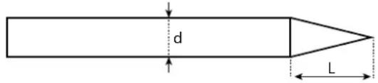
ELECTRODE SHARPENING
For optimum results, it is advised to use an electrode sharpened in the following way:
text_image
d LL = 3 x d for a low current. L = d for a high current
RECOMMENDED COMBINATIONS
 (mm) (mm) | Current (A) ∅ Electrode (mm) ∅ Nozzle (mm) Argon flow rate (L/min) | |||
| 0.3 - 3 3 - 75 1 | 6.5 6 - 7 | |||
| 2.4 - 6 60 - 150 | 1.6 8 6 - 7 | |||
| 4 - 8 100 - 200 | 2 9.5 7 - 8 | |||
| 6.8 - 8.8 170 - 25 | 0 2.4 | 11 | 8 - 9 | |
| 9 - 12 | 225 - 300 3.2 12.5 | 9 - 10 | ||
PROCESS SETTINGS
| Settings | Settings | |
| Welding process | Standard | Smooth current |
| Pulsed | Pulsed current | |
| Spot welding | Smooth tacking | |
| Spot-Pulse | Pulsed tacking | |
| Trigger mode | 2T, 4T, Valve | Choice of trigger welding management mode. |
Access to some of the welding parameters depends on the selected display mode: Settings/Display mode: Easy or Expert. Refer to the HMI manual.
SETTINGS
- Standard
The standard DC TIG welding process allows high quality welding on most ferrous materials such as steel and stainless steel, but also copper and its alloys including titanium. The various current and gas management possibilities allow you to perfectly control your welding operation, from priming to the final cooling of your weld seam.
- Pulse
This pulsed current welding mode combines high current pulses (I = welding pulses) with low current pulses (cold I, workpiece cooling pulses). The pulsed mode allows parts to be assembled while limiting temperature rises and warping. Ideal for on site use.
Example:
The welding current (I) is set to 100 A and % (cold I) = 50%, i.e. cold current = 50% x 100 A = 50. F(Hz) is set to 10 Hz, the signal period will be 1/10 Hz = 100 ms -> a 100 A pulse every 100 ms then followed by another at 50 A.
- Spot
This welding mode allows the pre-assembly of parts before welding. Spot welding can be done manually using the trigger or timed with a predefined spot welding period. Spot welding allows for better reproduction and non-oxidised weld points.
- Spot-Pulse
This method of welding is used to pre-assemble thin sheet metal workpieces prior to the actual welding process. Spot welding can be done manually using the trigger or timed with a predefined spot welding period. Spot welding allows for better reproduction and non-oxidised weld points.
CHOOSING THE ELECTRODE'S DIAMETER
| Electrode (mm) | DC TIG | |
| Pure tungsten | Tungsten with oxides | |
| 1 | 10 > 75 | 10 > 75 |
| 1.6 | 60 > 150 | 60 > 150 |
| 2 | 75 > 180 | 100 > 200 |
| 2.5 | 130 > 230 | 170 > 250 |
| 3.2 | 160 > 310 | 225 > 330 |
| Approx. = 80 A per mm | ||
USING THE TRIGGER
• 2T
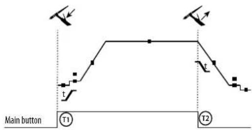
text_image
Main button T1 T2T1 - The main button is pressed, the welding cycle starts (Pre-Gas, I_Start, upslope and welding).
T2 - The main button is released, the welding cycle is stopped (downslope, I_Stop, Post-Gas).
For two-button torches in T2 only, the secondary button is treated as the main button.
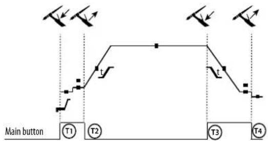
• 4T
flowchart
graph TD
    A["Main button"] --> B["T1"]
    B --> C["T2"]
    C --> D["T3"]
    D --> E["T4"]
    style A fill:#f9f,stroke:#333
    style B fill:#ccf,stroke:#333
    style C fill:#cfc,stroke:#333
    style D fill:#fcc,stroke:#333
    style E fill:#ffc,stroke:#333
T1 - The main button is pressed, the cycle starts from Pre-Gas and stops at the I_Start phase.
T2 - The main button is released, the cycle continues to upslope and welding.
T3 - The main button is pressed, the cycle goes to downslope and stops in the I_Stop phase.
T4 - The main button is released, the cycle ends with the Post-Gas. NB: for torches, double buttons and double button + potentiometer => «up/weld current» button turns on the potentiometer, the «down» button turns it off.
For dual button or dual trigger torches, the «high» trigger retains the same functionality as the single trigger torch. The «low» trigger is not active.
CONFIGURING THE SETTINGS
Units
| End current % This idling current is the next phase after the current is lowered. | ||
| Starting current % This start-up bearing current is a warm-up phase before the current is raised. | ||
| Welding current A Welding current. | ||
| Cold current % Second welding current known as a «cold» welding current. | ||
| Pulse duration s Manual or time-controlled spot pulse phase | ||
| Spot duration s Either manual or a set time. | ||
| Crater-fill feature | s | Avoids cratering at the end of welding and the risk of cracking, particularly in light alloys. |
| Pulse frequency Hz | Pulse frequency (setting guidelines):- If welding with manual filler metal, then the F(Hz) is synchronised to the filler action,- If the metal is thin and without filler (< 0.8mm), F(Hz) > 10Hz- If welding in position, then F(Hz) < 100Hz | |
| Rising current | s Allows a gradual increase in welding current. | |
| Post-Gas | s | Duration of the gas protection after the arc is extinguished. It protects the workpiece and the electrode from oxidation during cooling. |
| Pre-Gas | s When the torch is bled and the gas shield is created before ignition. | |
| Stopping time | s This idling time is a phase that comes after the current is lowered. | |
| Starting time s Starting time before the current is raised. | ||
| Cold weather | % Pulsed hot current (I) time balance | |
Access to some of the welding parameters depends on the selected display mode: Settings/Display mode: Easy or Expert. Refer to the HMI manual.
MANUAL GAS PURGE
The presence of oxygen in the torch can lead to a decrease in mechanical quality and can result in less corrosion resistance. To flush the gas from the torch, press and hold button no. 1 and follow the on-screen procedure. Refer to the HMI manual.
MMA (SMAW) WELDING MODE
INSTALLATION AND GUIDANCE
- Plug the cables, electrode holder and earth clamp into the plug connections.
- Respect the electrical polarities and the strength of the welding power indicated on the electrode boxes.
- Remove the coated electrode from the electrode holder when the welding power source is not in use.
• The equipment is fitted with 3 inverter-specific features: - Hot Start provides an overcurrent at the beginning of the welding process.
- Arc Force creates an overcurrent which prevents the electrode from sticking to the weld pool.
- The Anti-Stick technology makes it easier to unstick the electrode from the metal.
PROCESS SETTINGS
| Welding processes | ||||
| Settings Settings Standard Pulsed | ||||
| Electrode type | RutileBasic | √ | √ | The type of electrode determines the settings in order to optimise its weldability depending on the type of electrode used. |
| Anti-Sticking ON-OFF | √ | √ | The anti-stick feature is recommended to safely remove the electrode in the event of it sticking to the workpiece (the current is cut off automatically). | |
Access to some of the welding parameters depends on the selected display mode: Settings/Display mode: Easy or Expert. Refer to the HMI manual.
WELDING PROCESSES
- Standard
This standard MMA welding mode is suitable for most welding applications. It enables welding with all types of coated, rutile, basic and cellulosic electrodes, as well as on all materials: steel, stainless steel and cast iron.
- Pulse
The pulsed MMA welding mode is suitable for upright (PF) applications. The pulsed setting keeps the weld pool cold while promoting material transfer. Without pulsing, vertical upward welding requires a 'Christmas tree' movement, i.e. a difficult triangular movement. Thanks to Pulsed MMA welding, it is no longer necessary to perform this movement. Depending on the thickness of your workpiece, a straight upward movement should suffice. However, if you want to enlarge your weld pool, a simple sideways movement similar to downheld welding is sufficient.. In this case, you can set the frequency of your pulsed current on the display screen. This method offers greater control of the vertical welding operation.
CHOOSING COATED ELECTRODES
- Rutile electrodes: very easy to use in any position.
- Basic electrodes: it can be used in all positions and is suitable for safety work due to its increased mechanical properties.
CONFIGURING THE SETTINGS
| Units | ||
| Arc Force | Arc Force is an overcurrent administered to prevent sticking when the electrode or weld bead touches the weld pool. | |
| Welding current A The welding current is determined by the type of electrode chosen (see electrode packaging). | ||
| Duration of Hot Start s | Hot Start is an overcurrent at the ignition stage which prevents the electrode from sticking to the workpiece. The intensity (% of welding current) and the time (seconds) can be programmed. | |
| Pulse frequency | Hz PULSE mode's PULSING frequency. | |
| Percentage Hot Start % | Hot Start is an overcurrent at the ignition stage which prevents the electrode from sticking to the workpiece. The intensity (% of welding current) and the time (seconds) can be programmed. | |
| Percentage I cold % | ||
| Cold weather s | ||
Access to some of the welding parameters depends on the selected display mode: Settings/Display mode: Easy or Expert. Refer to the HMI manual.
ADJUSTING THE WELDING INTENSITY
The following settings correspond to the applicable current range depending on the type and diameter of the electrode used. These ranges are quite large as they depend on the usage and the welding position.
| electrode ∅ (mm) Rutile E6013 (A) | Basic E7018 (A) | |
| 1.6 | 30-60 | 30-55 |
| 2.0 | 50-70 | 50-80 |
| 2.5 | 60-100 | 80-110 |
| 3.15 | 80-150 | 90-140 |
| 4.0 | 100-200 | 125-210 |
| 5 | 150-290 | 200-260 |
| 6.3 | 200-385 | 220-340 |
ADJUSTING THE ARC FORCE
It is advisable to set the Arc Force to the middle position (0) to start welding and then adjust it according to the results obtained and individual welding preferences. Note: The adjustment range of the Arc Force is specific to the type of electrode chosen.
ROLLERS (B) OPTIONAL
| Diameter | Reference (x2) | |
| Steel Aluminum Flux-cored wire | ||
| 0.6/0.8 042353 - 0.9/1.2 042407 | ||
| 0.8/1.0 042360 042377 | ||
| 1.0/1.2 046849 040915 | ||
| Diameter | Reference (x2) |
SEPARATE WIRE FEEDER WF 35
natural_image
Technical line drawing of a mechanical device with wheels and control panel (no text or symbols)The KRONOS 400T DUO product can be fitted with a separate WF 35 wire feeder (option, ref. 075078) in order to quickly use 2 different wire types or diameters without changing torches or spools. The connection between these two parts is made through a dedicated cable link, available separately:
| Type of torch cooling Length | Section Reference | ||
| Air | 5m 70mm ^2 075443 | ||
| 10m | 70mm ^2 075450 | ||
| 95mm ^2 077553 | |||
| Water | 1.8m 70mm ^2 075467 | ||
| 5m 70mm ^2 075474 | |||
| 10m | 70mm ^2 075481 | ||
| 95mm ^2 075504 | |||
For connecting the interconnection between the power source and the wire feeder, refer to the wire feeder manual.
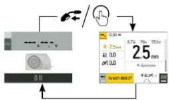
i It is not possible to use 2 MIG/MAG torches at the same time. When one reel is activated, the other is inactive.
HMI - wire feeder active HMI - wire feeder inactive
text_image
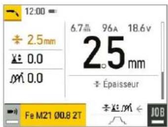
12:00 ÷ 2.5mm × 0.0 × M 0.0 6.7 mm 96A 18.6V 25 mm ÷ Épaisseur Fe M21 Ø0.8 2T ÷ × M ← JOB
text_image
1/U A V 3.8 ONTo switch from an inactive wire feeder to an active wire feeder, press the trigger on the non-active torch or press the thumbwheel on the non-active display.
flowchart
graph TD
    A["Input"] --> B["Processing Unit"]
    B --> C["Output"]
    C --> D["Display: 2.5mm, 0.0, 0.0, 0.0, 0.0, 0.0, 0.0, 0.0, 0.0, 0.0, 0.0, 0.0"]
DEFECTS: CAUSES & SOLUTIONS
| SYMPTOMS POSSIBLE CAUSES SOLUTIONS | ||
| The flow rate of the welding wire is not constant. | Clogs blocking the opening. | Clean the contact tube or replace it with non-stick material. |
| The wire is slipping on the rollers. Reapply the non-stick product. | ||
| One of the rollers is spinning. | Check the tightness of the roller screw. | |
| The torch cable is twisted. | The torch cable should be as straight as possible. | |
| The unwinding mechanism is not working. | The spool's brake or roller is too tight. | Loosen the brake and rollers. |
| Incorrect unwinding of the wire. | Dirty or damaged wire guide. | Clean or replace. |
| Roller pin key is missing. | Reposition the pin in its slot. | |
| Spool's brake is too tight. | Release the brake. | |
| No current or wrong welding current. | Incorrect mains outlet connection. | Check the plug connection and verify that the plug is connected to the power supply. |
| Poor earth connection. | Check the earthing cable (its connection and the condition of the clamp). | |
| No power. Check the torch trigger. | ||
| The wire jams after passing through the rollers. | Crushed wire guide sheath. | Check the wire-guide sheath and body of the torch.. |
| Wire blockage in the torch. Replace or clean. | ||
| No capillary tube. Check that the capillary tube is present. | ||
| Wire speed too high. Reduce the wire speed. | ||
| The weld bead is porous. | The gas flow is insufficient. | Adjustment range from 15 to 20 L / min.Clean the base metal. |
| Gas cylinder empty. Replace it. | ||
| Unsatisfactory gas quality. Replace it. | ||
| Air circulation or wind influence. Avoid draughts and protect the welding area. | ||
| Gas nozzle is too clogged. Clean or replace the gas nozzle. | ||
| Bad wire quality. Use a wire suitable for MIG/MAG welding. | ||
| Condition of the welding surface is too poor (rusted, etc.). | Clean the workpiece before welding. | |
| The gas is not connected. | Check that the gas is connected to the power source's inlet. | |
| Excessive sparks. | Arc voltage is too low or too high. See welding settings. | |
| Poor earth connection. | Check and position the earth clamp as close as possible to the area to be welded. | |
| Insufficient gas protection. Adjust the gas flow. | ||
| No gas coming from the torch. Poor gas connection. | Check the connections of gas inlets. | |
| Check that the solenoid valve is working. | ||
| Error while downloading. | The data on the USB stick is incorrect or corrupted. | Check your data. |
| Backup error. | You have exceeded the maximum number of backups. | You need to delete some programs.The number of backups is limited to 200. |
| Automatic deletion of JOBS. | Some of your JOBs have been deleted because they were incompatible with the new pre-installed user settings (synergies). | - |
| USB key error. | There is no JOB detected on the USB stick. - | |
| The product's memory space is full. Free up some space on the USB key. | ||
| File error. | The file does not match the pre-installed user settings (synergies) downloaded to the product. | The file was created with pre-installed user settings (synergies) that are not present on the machine. |
| Update problem | The USB stick is not recognised. The visualisation of step 5 of the update procedure does not appear on the display. | 1- Insert the USB key into its socket.2- Turn on the power source.3- Hold down on the HMI thumbwheel to force the update. |
WARRANTY CONDITIONS
The warranty covers any defects or manufacturing faults for two years from the date of purchase (parts and labour).
The warranty does not cover:
- Any other damage caused during transport.
• The general wear and tear of parts (i.e.: cables, clamps, etc.) - Incidents caused by misuse (incorrect power supply, dropping or dismantling).
- Environment-related faults (such as pollution, rust and dust).
In the event of a breakdown, please return the appliance to your distributor, along with:
- dated proof of purchase (receipt, invoice, etc.),
a note explaining the malfunction.
natural_image
Technical line drawing of a mechanical component with no visible text or symbolsnatural_image
Line drawing of a portable electronic device with control panel and cables (no text or symbols)natural_image
Line drawing of a mobile device with wheels and control panel (no text or symbols)natural_image
Technical line drawing of a mechanical device with wheels and control panel (no text or symbols)text_image
I/U A V ONWAARSCHUWINGEN - VEILIGHEIDSINSTRUCTIES
ALGEMENE INSTRUCTIES
natural_image
Pure diagram of a vertical cylindrical structure with directional arrows indicating flow or movement (no text or symbols)natural_image
Technical line drawing of a mechanical component with no visible text or symbolsnatural_image
Front view of a portable industrial machine with control panel and wiring (no visible text or symbols)natural_image
Line drawing of a mechanical device with wheels and control panel (no text or symbols)MMA (SMAW) LASMODULE
AANSLUITING EN ADVIEZEN
natural_image
Technical line drawing of a mechanical device with wheels and control panel (no text or symbols)text_image
1/U A V 8.8 ONnatural_image
Technical line drawing of a mechanical component with no visible text or symbolsnatural_image
Line drawing of a portable electronic device with control panel and wiring (no text or symbols)natural_image
Line drawing of a mobile phone chassis with wheels and control panel (no text or symbols)MODALITÀ DI SALDATURA MMA (SMAW)
COLLEGAMENTO E CONSIGLI
natural_image
Technical line drawing of a mechanical device with wheels and control panel (no text or symbols)text_image
1/U A V 3/8 ONtext_image
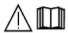
Exploded view diagram of an industrial air conditioning unit with numbered components and labeled parts| 400T DUO | ||
| 1 Embase Texas Femelle / Female Texas socket 51478 | ||
| 2 Interrupteur bipolaire / Two-pole switch 52472 | ||
| 3 Poignée plastique / Plastic handle 56047 | ||
| 4 IHM / HMI E0123C | ||
| 5 Capteur de courant / Current sensor 64463 | ||
| 6 Carte principale / Primary board E0125C | ||
| 7 Carte contrôle / Control board E0124C | ||
| 8 Ventilateur 60x60x20 / Fan 60x60x20 51028 | ||
| 9 Bloc Faible Courant / Low-current block E5047 | ||
| 10 Carte alimentation / Power supply board E0167 | ||
| 11 Transformateur / Transformer 63556 | ||
| 12 Self de sortie / Output choke | 63557 | |
| 13 Carte de puissance / Power board | E0126C | |
| 14 Ventilateur 92x92x38 / Fan 92x92x38 50999 | ||
| 15 Motodévidoir / Feed motor | 51208 | |
| 16 Carte tachymétrie / Tachometer board E0153C | ||
| 17 Support Bobine / Reel holder | 71613 | |
| 18 Electrovanne / Solenoid valve | 70991 | |
| 19 Carte adaptation faisceau / Interconnection adaptation board | E0134C | |
| 20 Cordon Secteur / Mains cable | 21589 | |
| 21 Roue diamètre 200 / Wheel diameter 200 | 71375 | |
| 22 Roue pivotante / Castor wheel | 71360 | |
| 23 Module IGBT / IGBT module | 52204 | |
| 24 Module diodes secondaires / Secondary diode module | 52225 | |
| 25 Module Pont de Diodes / Diode Bridge Module 52196 | ||
400T W
text_image
Exploded view diagram of an industrial machine with numbered components for identification and assembly reference.| 400T W | ||
| 1 Embase Texas Femelle / Female Texas socket 51478 | ||
| 2 Raccord eau rouge / Red coolant connector 71695 | ||
| 3 Raccord eau bleu / Blue coolant connector 71694 | ||
| 4 Interrupteur bipolaire / Two-pole switch 52472 | ||
| 5 Poignée plastique / Plastic handle 56047 | ||
| 6 IHM / HMI E0123C | ||
| 7 Capteur de courant / Current sensor 64463 | ||
| 8 Carte principale / Primary board E0125C | ||
| 9 Carte contrôle / Control board E0124C | ||
| 10 Ventilateur 60x60x20 / Fan 60x60x20 51028 | ||
| 11 Bloc Faible Courant / Low-current block E5047 | ||
| 12 Carte alimentation / Power supply board | E0167 | |
| 13 Transformateur / Transformer | 63556 | |
| 14 Self de sortie / Output choke | 63557 | |
| 15 Carte de puissance / Power board | E0126C | |
| 16 Ventilateur 92x92x38 / Fan 92x92x38 50999 | ||
| 17 Motodévidoir / Feed motor | 51208 | |
| 18 Carte tachymétrie / Tachometer board E0153C | ||
| 19 Support Bobine / Reel holder | 71613 | |
| 20 Electrovanne / Solenoid valve | 70991 | |
| 21 Cordon Secteur / Mains cable | 21589 | |
| 22 Reservoir eau / Water tank | M0204 | |
| 23 Carte groupe froid / Cooling unit board | 97772C | |
| 24 Pompe / Pump | 55327 | |
| 25 Radiateur eau / Water radiator | 71996 | |
| 26 Porte fusible / Fuse holder | 51387 | |
| 27 Fusible / Fuse | 51401 | |
| 28 Roue pivotante / Castor wheel | 71360 | |
| 29 Roue diamètre 200 / Wheel diameter 200 | 71375 | |
| 30 Module IGBT / IGBT module | 52204 | |
| 31 Module diodes secondaires / Secondary diode module | 52225 | |
| 32 Module Pont de Diodes / Diode Bridge Module 52196 | ||
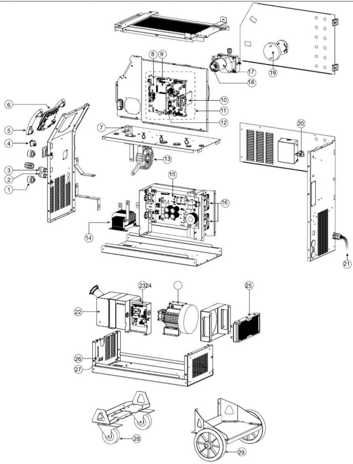
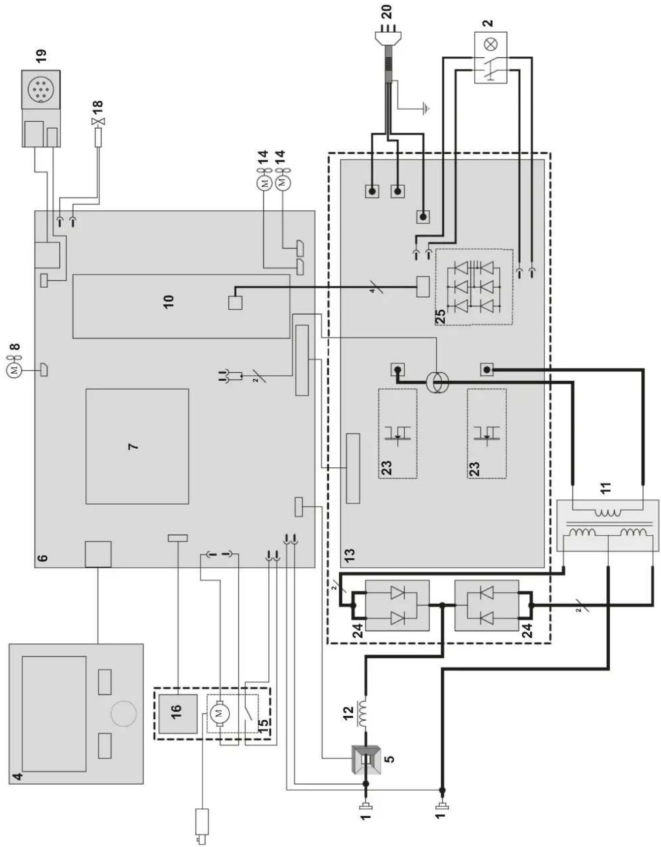
CIRCUIT DIAGRAM / SCHALTPLAN / DIAGRAMA ELECTRICO / ЭЛЕКТРИЧЕСКАЯ СХЕМА / ELEKTRISCHE SCHEMA / SCEMA ELETTRICO
400T DUO
flowchart
graph TD
    A["19"] --> B["18"]
    B --> C["10"]
    C --> D["7"]
    D --> E["6"]
    E --> F["4"]
    F --> G["16"]
    G --> H["15"]
    H --> I["12"]
    I --> J["5"]
    J --> K["1"]
    K --> L["1"]
    L --> M["1"]
    M --> N["12"]
    N --> O["24"]
    O --> P["23"]
    P --> Q["25"]
    Q --> R["20"]
    R --> S["2"]
    S --> T["25"]
    T --> U["23"]
    U --> V["24"]
    V --> W["11"]
    W --> X["12"]
    X --> Y["13"]
    Y --> Z["14"]
    Z --> AA["14"]
    AA --> AB["14"]
    AB --> AC["14"]
    AC --> AD["14"]
    AD --> AE["14"]
    AE --> AF["14"]
    AF --> AG["14"]
    AG --> AH["14"]
    AH --> AI["14"]
    AI --> AJ["14"]
    AJ --> AK["14"]
    AK --> AL["14"]
    AL --> AM["14"]
400T W
flowchart
graph TD
    A["1"] --> B["2"]
    B --> C["3"]
    C --> D["4"]
    D --> E["5"]
    E --> F["6"]
    F --> G["7"]
    G --> H["8"]
    H --> I["9"]
    I --> J["10"]
    J --> K["11"]
    K --> L["12"]
    L --> M["13"]
    M --> N["14"]
    N --> O["15"]
    O --> P["16"]
    P --> Q["17"]
    Q --> R["18"]
    R --> S["19"]
    S --> T["20"]
    T --> U["21"]
    U --> V["22"]
    V --> W["23"]
    W --> X["24"]
    X --> Y["25"]
    Y --> Z["26"]
    Z --> AA["27"]
    AA --> AB["28"]
    AB --> AC["29"]
    AC --> AD["30"]
    AD --> AE["31"]
    AE --> AF["32"]
    AF --> AG["33"]
    AG --> AH["34"]
    AH --> AI["35"]
    AI --> AJ["36"]
    AJ --> AK["37"]
    AK --> AL["38"]
    AL --> AM["39"]
    AM --> AN["40"]
TECHNICAL SPECIFICATIONS / TECHNISCHE DATEN / ESPECIFICACIONES TÉCNICAS / ТЕХНИЧЕСКИЕ СПЕЦИФИКАЦИИ / TECHNISCHE GEGEVENS / SPECIFICHE TECNICHE
| 400T DUO 400T W | ||||
| Primaire / Primary / Primär / Primario / Первичка / Primaire / Primario | ||||
| Tension d'alimentation / Power supply voltage / Versorgungsspannung / Tensión de red eléctrica / Напряжение питания / Voedingss- panning / Tensione di alimentazione | U1 | 400 V +/- 15% | ||
| Fréquence secteur / Mains frequency / Netzfrequenz / Frecuencia / Частота сети / Frequentie sector / Frequenza settore | 50 / 60 Hz | |||
| Nombre de phases / Number of phases / Anzahl der Phasen / Número de fases / Количество фаз / Aantal fasen / Numero di fase | 3 | |||
| Fusible disjoncteur / Fuse / Sicherung / Fusible disyuntor / Плавкий предохранитель прерывателя / Zekering hoofdschakelaar / Fusibile disgiuntore | 32 A | |||
| Courant d'alimentation effectif maximal / Maximum effective supply current / Corriente de alimentación efectiva máxima / Maximale effectieve voedingsstroom / Corrente di alimentazione effettiva massima / Maksymalny efektywny prąd zasilania | I1eff | 21 A | ||
| Courant d'alimentation maximal / Maximum supply current / Corriente de alimentación máxima / Maximale voedingsstroom / Corrente di alimentazione massima / Maksymalny prąd zasilania | I1max | 36 A | ||
| Section du cordon secteur / Mains cable section / Sectie netsnoer / Sección del cable de alimentación / Sezione del cavo di alimenta- zione / Odinek przewodu zasilającego | 4 x 4 mm2 | |||
| Puissance active maximale consommée / Maximum active power consumed / Consumo máximo de energía activa / Maximale actieve verbruikte vermogen / Potenza attiva massima consumata / Maksymalny pobór mocy czynnej | 16.6 kW | |||
| Consommation au ralentí / Idle consumption / Consumo en ralentizado / Stationair verbruik / Consumo al minimo / Zużycie na biegu jałowym | 25.32 W | |||
| Rendement à I2max / Efficiency at I2max / Eficiencia a I2max / Rendement bij I2max / Efficienza a I2max / Sprawność przy I2max | 87 % | |||
| Facteur de puissance à I2max / Power factor at I2max / Factor de potencia a I2max / Inschakelduur bij I2max / Ciclo di potenza a I2max / Współczynnik mocy przy I2max | λ | 0.66 | ||
| Classe CEM / EMC class / Classe CEM / Klasse CEM / Classe CEM / Klasa EMC A | ||||
| Secondaire / Secondary / Sekundär / Secundario / Вторичка / Secondair / Secondario | MMA (SMAW) | TIG (GTAW) | MIG-MAG (GMAW-FCAW) | |
| Tension à vide / No load voltage / Leerlaufspannung / Tensión al vacío / Напряжение холостого хода / Nullastspanning / Tensione a vuoto | U0 (TCO) | 66 V | ||
| Nature du courant de soudage / Type of welding current / Tipo de corriente de soldadura / Type lasstroom / Tipo di corrente di saldatura / Rodzaj prądu spawania | DC | |||
| Modes de soudage / Welding modes / Modos de soldadura / Lasmodules / Modalità di saldatura / Tryby spawania | MMA, TIG, MIG-MAG | |||
| Courant de soudage minimal / Minimum welding current / Corriente mínima de soldadura / Minimale lasstroom / Corrente mínima di saldatura / Minimalny prąd spawania | 20 A 20 A 15 A | |||
| Courant de sortie nominal / Rate current output / nominaler Arbeitsstrom / Corriente de salida nominal / Номинальный выходной ток / Nominale uitgangsstroom / Corrente di uscita nominale | I2 | 20 → 400 A | 20 → 400 A | 15 → 400 A |
| Tension de sortie conventionnelle / Conventional voltage output / entsprechende Arbeitsspannung / Условное выходные напряжения / Tensión de salida convencional / Conventionele uitgangsspanning / Tensione di uscita convenzionale | U2 | 20.8 → 36 V 10.8 | → 26V 14.75 → 34 V | |
| * Facteur de marche à 40°C (10 min), Norme EN60974-1 / Duty cycle at 40°C (10 min), Standard EN60974-1. Einschaltdauer @ 40°C (10 min), EN60974-1-Norm / Ciclo de trabajo a 40°C (10 min), Norma EN60974-1/ ПВ% при 40°C (10 мин), Норма EN60974-1. / Inschakelduur bij 40°C (10 min), Norm EN60974-1, Ciclo di lavoro a 40°C (10 min), Norma EN60974-1. | Imax | 35 % 35 % 35 % | ||
| 60 % | 300 A | 340 A | 300 A | |
| 100 % | 280 A | 300 A | 280 A | |
| Diamètre minimal et maximal du fil d'apport / Minimum and maximum diameter of filler wire / Minimaler und maxi- maler Durchmesser des Schweißfülldrahtes / Diámetro mínimo y máximo del hilo de soldadura / Минимальный и максимальный диаметр присадочной проволоки / Minimale en maximale diameter van het lasdraad / Diametro mínimo o massimo del filo d'apporto | Acier / Steel | 0.6 → 1.2 mm | ||
| Inox / Stainless | 0.6 → 1.2 mm | |||
| Aluminium | 0.8 → 1.2 mm | |||
| Fil fourré / Wire cored | 0.9 → 1.6 mm | |||
| CuSi / CuA | 0.8 → 1.0 mm | |||
| Connectique de torche / Torch connector / Brenneranschluss / Conexiones de antorcha / Соединения горелки / Aansluiting toorts / Connettori della torcia | Euro | |||
| Type de galet / Drive roller type / Drahtführungsrolle-Typ / Tipo de rodillo / Тип ролика / Type draadaanvoerrol / Tipo di rullo | B | |||
| Vitesse de dévidage / Motor speed / Motor-Drehzahl / Velocidad de motor / Скорость двигателя / Snelheid motor / Velocità del motore | 1.5 → 20 min/min | |||
| Puissance du moteur / Motor power / Leistung des Motors / Potencia del motor / Vermogen van de motor / Potenza del motore | 50 W | |||
| Diamètre maximal de la bobine d'apport / Maximum diameter of the supply reel / Maximaler Durchmesser der Schweißfülldrahtspule / Diámetro máximo de la bobina de alambre / Максимальный диаметр проволочной бобины / Maximale diameter van de spoel / Diametro massimo della bobina d'apporto | ∅ 300 mm | |||
| Poids maximal de la bobine de fil d'apport / Maximum weight of the filler wire reel / Maximales Gewicht der Schweißfülldrahtspule / Peso máximo de la bobina de alambre / Максимальный вес проволочной бобины / Maximale gewicht van de spoel / Peso massimo della bobina del filo d'apporto | 18 kg | |||
| Pression maximale de gaz / Maximum gas pressure / Maximaler Gasdruck / Presión máxima del gas / Максимальное давление газа / Maximale gasdruk / Pressione massima del gas | 0.5 MPa (5 bar) | |||
| Puissance de refroidissement à 1l/min à 25°C / Cooling power at 1l/min at 25°C / Kühlleistung bei 1l/min bei 25°C / Potencia frigorifica a 1 l/min a 25°C / Мощность охлаждения 1 л/мин при 25°C / Koelvermogen 1l/min bij 25°C / Potenza di raffreddamento a 1l/min à 25°C | P1 L/min - | 0.8 kW | ||
| Facteur de correction de la puissance de refroidissement à 40°C / Correction factor 40°C / Korrekturfaktor bei 40°C / Factor de corrección a 40°C / Коэффициент коррекции при 40°C / Correctiefactor bij 40°C / Ciclo di correzione a 40°C | -0.58 | |
| Pression maximale / Maximum pressure / Maximaler Druck / Presión máxima / Максимальное давление / Maximale druk / Pression massima / Maximale druk Pmax | -0.53 MPa | |
| Température de fonctionnement / Functionning temperature / Betriebstemperatur / Temperatura de funcionamiento / Рабочая температура / Gebruikstemperatuur / Temperatura di funzionamento | -10°C → +40°C | |
| Température de stockage / Storage temperature / Lagertemperatur / Temperatura de almacenaje / Температура хранения / Bewaartemperatuur / Temperatura di stoccaggio | -20°C → +55°C | |
| Degré de protection / Protection level / Schutzart / Grado de protección / Степень защиты / Beschemingsklasse / Grado di protezione | IP23S | |
| Classe d'isolation minimale des enroulements / Minimum coil insulation class / Clase mínima de aislamiento del bobinado / Minimale isolatieklasse omwikkelingen / Classe minima di isolamento degli avvolgimenti / Minimalna klasa izolacji okablowania | B | |
| 400T DUO 400T W | ||
| Dimensions (Lxlxh) / Dimensions (LxWxH) / Abmessungen (Lxbxt) / Dimensiones (Lxlxh) / Размеры (ДхШхВ) / Afmetingen (Lxlxh) / Dimensioni (Lxlxh) | 90 x 55 x 67 cm 90 x 55 x 81 cm | |
| Poids / Weight / Gewicht / Bec / Peso / Gewicht / Peso 55 kg 70 kg | ||
The duty cycles are measured according to standard EN60974-1 à 40°C and on a 10 min cycle. While under intensive use (> to duty cycle) the thermal protection can turn on. In that case, the arc switches off and the indicator switches on. Keep the machine's power supply on to enable cooling until thermal protection cancellation. The welding power source describes an external dropping characteristic. The power supply shows a flat output pattern... In some countries. UO is called TCO.
This interface (HMI) manual forms part of the complete item documentation. A general manual is included with the product. Read and follow the general manual's instructions, particularly the safety instructions!
For use and application to the following products only
| KRONOS 250M | √ |
| KRONOS 250T | √ |
| KRONOS 320T | √ |
| KRONOS 400T DUO | √ |
| KRONOS 400T W | √ |
| WF 35 | √ |
Software version
This manual covers the following software versions:
1.0
The software version of the interface is displayed in the general menu: Système / Information
Control of the power source
The main screen displays all the information needed before, during, and after welding. The interface is adjustable with 2 different display modes: Easy or Expert.
MIG-MAG (GMAW/FCAW) TIG (GTAW)
text_image
SMART INVERTER TECHNOLOGY 1 10:36 2 1.0mm 3 0.0 4 m 0.0 5 Fe M21 Ø0.8 2T 6 3.2A 51A 14.6V 1.0 mm Thickness 9 8 7 press 3s6
text_image
SMART INVERTER TECHNOLOGY 1 10:50 2 I 100A \t 1.8s 100 A I Welding current 3 Standard - 2T I \t JOB 9 8 5 press 3s 76
| [2x85] | ||
| 1 | Current welding process Schedule, Traceability | |
| 2 | Current settings | |
| 3 | Gas flow control (Hold down / long press) | BP1 |
| 4 | Current process settings BP1 | |
| 5 | Push-button no. 1 (BP1) | |
| 6 | Navigation/setting thumbwheel Short press to confirm Long press = General menu | |
| 7 | Push-button no. 2 (BP2) | |
| 8 | Advanced settings BP2 | |
| 9 | Access to the JOB (long press) BP2 | |
| (TT6D) | |
| 1 Current welding processSchedule, Traceability | |
| 2 Current settings | |
| 3 Gas purge (long press) BP1 | |
| 4 Current process settings BP1 | |
| 5 Push-button no. 1 (BP1) | |
| 6 Navigation/setting thumbwheelShort press to confirmLong press = General menu | |
| 7 Push-button no. 2 (BP2) | |
| 8 Advanced settings BP2 | |
| 9 Access to the JOB (long press) BP2 |
Control of the power source
The main screen displays all the information needed before, during, and after welding. The interface is adjustable with 2 different display modes: Easy or Expert.
MMA (SMAW)
text_image
SMART INVERTER TECHNOLOGY 1 10:54 250 A I Welding current Standard - Basique I ← JOB 7 6 3 5 press 3s4
| ↓ | |
| 1 Current welding processSchedule, Traceability | |
| 2 Current process settings BP1 | |
| 3 Push-button no. 1 (BP1) | |
| 4 Navigation/setting thumbwheelShort press to confirmLong press = General menu | |
| 5 Push-button no. 2 (BP2) | |
| 6 Advanced settings BP2 | |
| 7 Long press BP2 (Hold down) BP2 |
General menu
The navigation between the different sections is done with the thumbwheel.
From the home screen, a long press on the thumbwheel takes you to the main menu. Briefly pressing button no. 1 (◀ returns to the previous menu or accesses the main screen.
text_image
SMART INVERTER TECHNOLOGY Processes Settings System Portability press 35Processes
MIG-MAG (GMAW/FCAW)
Semi-automatic, gas shielded welding
TIG (GTAW)
Gas shielded welding with a non-fusible tungsten electrode
MMA (SMAW)
Arc welding with a coated electrode
Settings
Display mode
- Easy: simplified display suitable for the vast majority of users.
- Expert: comprehensive display suitable for more experienced welders. Allows you to adjust the durations of the different phases in the welding cycle.
Language
Choice of the interface language (French, English, German, etc).
Units of measurement
Choice of measurement units: International (SI) or Imperial (USA).
Name of materials
European standard (EN) or American standard (AWS).
Luminosity
Adjusts the brightness of the interface screen (setting from 1 (dark) to 10 (very bright)).
System
Device name:
Device name information and customisation options.
Clock:
Setting the time, date and format (AM/PM).
Cooling unit (only for machines equipped with a cooling system)
- OFF: the cooling unit is deactivated.
- ON: the cooling unit is permanently active.
- AUTO: automatic operation (activates during welding and deactivates 10 minutes after the end of welding)
PURGE function specifically dedicated to the purging of the cooling unit or filling of the hoses, the protections are disabled (see the general instructions for safe purging of your product).
Information
Configuration data of the product's system components:
- Model
- Serial number
- Device name
- Software version

Press push-button no. 2:
Exporting the machine configuration to the USB stick (not supplied)
Productivity
Product usage data :
- Ignition time
- Welding time
- etc.
Reset
Resets the product settings:
- Partial: defaults the values of the current welding process.
- Total: all the machine's configuration will be reset to the factory settings.
Traceability\*
*This feature is not activated as default. It can be activated via the online configurator, available on Planet GYS / Tools / Product configuration. To activate it, contact your distributor.
This welding management interface is designed to trace/record all the steps of the welding operation, bead by bead, during manufacturing. This qualitative approach ensures a post-production welding quality that allows the analysis, evaluation, reporting and documentation of the recorded welding parameters. This feature allows for the accurate and fast collection and storage of data required under EN ISO 3834. This data can be recovered and exported with a USB stick.
1- Start - Creation of traceability
- Customise the name of the job by pressing the thumbwheel.
- Sampling interval:
- Hold: No recording of current/voltage values (average along the wire) during welding.
- 250 ms, 500 ms, etc. : recording of current/voltage values (average along the wire) every «X» milliseconds or seconds during welding.
Press «REC» to start traceability
Traceability display
At the top left of the main screen, a red symbol is displayed to indicate that a record is being made for traceability.
Stop - Stopping traceability
To end tracking during a welding operation, the user must return to the Traceability block and select «Stop».
Exporting
The recovery of this information is done by exporting the data to a USB stick (not supplied).
The CSV data can be processed with a spreadsheet program (Microsoft Excel®, Calc OpenOffice®, etc).
The file name is linked to the machine name and serial number.
2- Start - Traceability management
The screen lists previously created jobs.
Short pressing push-button no. 1 returns to the previous menu
Holding down on push-button no.1 (deletes the active job or all jobs.
Holding down push-button no. 2 (▶ creates a new traceability.
Short pressing push-button no. 2 (i) allows you to see the details of each of the previously created jobs.
Portability
Import Config.
Loading the configuration from the USB stick (directory: Removable disk\Portability\Config) to the machine. Holding down on the push-button no. 1 (deletes the configurations on the USB stick.
Export Config.
Export the machine configuration to the USB stick (directory : Removable disk\Portability\Config).
Import Job
Importing Jobs to the machine according to the processes available in the USB key's Removable Disk directory.
Export Job
Exporting Jobs from the machine to the USB stick procedure (directory : Removable disk\Portability\Job). Caution, old jobs on the USB stick may be deleted..
To prevent data loss during data import or export, do not remove the USB flash drive or turn off the machine. The file name is linked to the machine name and serial number. The USB stick is not included.
Calibration
Calib. Cables
Function dedicated to the calibration of welding accessories such as MIG torch, or electrode holder and ground clamp cables. The purpose of calibration is to compensate for variations in the length of the accessories in order to match the selected voltage value. Once started, the procedure is illustrated with an animation on the screen.
Important: The cable calibration must be repeated each time the torch, harness or ground cable is changed to ensure optimal welding performance.
Gas flow control (MIG-MAG)
In the main screen, holding down on button no. 1 allows you to adjust the gas flow on the manometer without unwinding the supply wire. Once started, the procedure is illustrated with an animation on the screen. The gas flow setting should be checked periodically to ensure optimal welding.
Gas purge (TIG)
The presence of oxygen in the torch can lead to a decrease in mechanical quality and can result in less corrosion resistance. To flush the gas from the torch, press and hold button no. 1 and follow the on-screen procedure.
Wire loading (MIG-MAG)

To unwind the wire in the MIG/MAG torch without using gas, please follow the procedure below:
1- Hold the trigger down in a non-welding position.
2- When the process is shown on the display, you can release the trigger.
3- The wire starts to feed. 3m of wire feeds at a speed of 5m/min by default. You can change these values with the thumbwheel.
If you wish to exit the animation without waiting for the wire to finish feeding, press the trigger briefly.
Job memory and recalls
Accessible through the «JOB» icon on the main screen.
The settings in use are automatically saved and remembered the next time you turn on the machine.
In addition to the active settings, it is possible to save and recall «JOB» configurations.
There are 200 JOBS for the MIG/MAG process and 100 for the TIG and MMA process. The storage is based on the current process parameters, and the current settings.
Job
This JOB mode allows you to create, save, recall and delete JOBs.
1- Save As - Creating a Job
Customise the job name by pressing the thumbwheel. Confirm by pressing push-button no. 2.
Display the current job
At the bottom right of the screen, the job number is displayed.
Stop the current job
To close the current job, the user must return to the Job menu and select «Close».
2- Open - Jobs Management
The screen lists previously created Jobs.
Short pressing push-button no. 1 returns to the previous menu
Holding down push-button no. 1 (deletes the selected Job or all the Jobs.
Short pressing push-button no. 2 (j) allows you to see the details of each of the previously created jobs.
QuickLoad – Recall JOBs from the trigger when not welding.
QuickLoad is a mode to recall jobs (20 max) outside of welding, and is only possible in MIG-MAG and TIG processes. From a list of previously created JOBs, JOB recalls are done by short trigger presses. All trigger modes and welding modes are supported.
1- New - Creating a QuickLoad
- Customise the name of the QuickLoad by pressing the thumbwheel.
- Choose the number of jobs to be recalled, between 2 and 20.
- Choose the trigger sensitivity: slow, normal or fast
• Choice of Jobs to be recalled
Press push-button no. 2 to confirm the creation of a QuickLoad.
Display the current QuickLoad
At the bottom right of the screen, the QuickLoad number is displayed.
Stopping the QuickLoad in progress
To close the current QuickLoad, the user must return to the Job/QuickLoad menu and select «Close».
2- Open - QuickLoad management
The screen lists previously created QuickLoads.
Short pressing push-button no. 1 returns to the previous menu
Holding down push-button no. 1 (deletes the selected QuickLoad or all the QuickLoads.
Holding down push-button no. 2 (✗) allows the selected QuickLoad to be modified.
Short pressing on push-button no. 2 Ⓞ allows you to see the details of each of the previously created QuickLoads.
Error codes
The following table shows a non-exhaustive list of messages and error codes that may appear. Carry out these checks and inspections before calling in an authorised GYS technician.

If the user needs to open the product, they must turn off the power supply by disconnecting the electrical plug from the socket, and wait two minutes for safety.
| Codes error | Messages Solutions | |
| 001 | OVER-VOLTAGE FAULTCheck the electrical installation | Have your mains supply checked by an authorised person. |
| 002 | UNDER-VOLTAGE FAULTCheck the electrical installation | |
| 005 Earth current fault | Presence of a stray current. Check the cabling of the welding accessories (torch, ground clamp, electrode holder, etc.) | |
| 006 | COOLING UNIT FAULTCooling unit not detected | The cooling unit is no longer being detected. Check the connection between the cooling unit and the power source. |
| 007 | FLOW ERRORCooling circuit blocked | Check the continuity of the torch's coolant flow. |
| Check the fuse of the cooling unit. | ||
| 008 | WATER LEVEL ERRORCheck the coolant level | Fill the tank of the cooling unit to the maximum (recommended coolant: Ref. 062511) |
| 009 | COOLING UNITThermal protection | Wait a few minutes for the cooling unit to cool down.Ensure that the recommended duty cycle for the selected welding current used is not exceeded.Ensure that air inlets and outlets are not obstructed. |
| 010 | POWER SOURCEThermal protection | Wait a few minutes for the power source to cool down.Ensure that the recommended duty cycle for the selected welding current used is not exceeded. |
| 011 | FanFan default. | Switch off the power supply by unplugging the mains connector, and check that the fan is not blocked. |
| 012 | TRIGGERA trigger is being pressed | Remove the torch and check to see if the message is still active.Check that the «Gas purge / Wire feed» switch is not blocked..Check that the trigger on the MIG/MAG torch is not blocked or stuck. |
| 015 | MOTORUnable to reach the required speed | Check the pressure settings on the wire-feeding rollers.Check that the welding wire is not blocked in the torch liner. |
| 019 | Overload, please check your settingsPress and release the trigger to erase | Check the power source settings and installation (welding wire, rollers, gas, torch, etc.)If the problem persists, update the software (via Planet GYS). |
| 020 | Problem with welding start-upPlease check your welding parametersPress and release the trigger to erase | Check the power source settings and installation (welding wire, rollers, gas, torch, etc.)If the problem persists, update the software (via Planet GYS). |
| 024 | USB overloadDisconnect your USB | Change the USB stick. |
| - | An internal system error has occurred.Please restart your product | Turn the product off and on again.If the problem persists, update the software (via Planet GYS) |
| - Calibration error Recalibrate the welding cables («Calibration» menu) | ||
| - | The product's memory space is full. Delete Jobs to | free up internal storage space. |
| - | File %s not supportedErr %dContinue anyway? | The data on the USB stick is corrupted. Check your data. |
| - Unable to write to USB stick | Free up some space on the USB key.If the problem persists, change the USB stick.. | |
| - | The USB stick is not recognised. The display of step 5 of the update procedure does not appear on the screen (see general instructions). | 1- Insert the USB key into its socket.2- Turn on the power source.3- Hold down on the HMI thumbwheel to force the update. |
If an error code which is not listed appears or your problems persist, contact your distributor.