
Thunder Sports MUD100.4 - Speaker MTX Audio - Free user manual and instructions
Find the device manual for free Thunder Sports MUD100.4 MTX Audio in PDF.
| Product Type | 4-Channel Audio Amplifier |
| Brand | MTX Audio |
| Model | Thunder Sports MUD100.4 |
| Output Power (RMS) | 50 W x 4 @ 4 Ω, 100 W x 4 @ 2 Ω, 200 W bridged @ 4 Ω |
| Minimum Impedance | 2 Ω (stereo), 4 Ω (bridged) |
| Frequency Response | 10 Hz - 32 kHz |
| Filters | Fixed low-pass filter (LPF) 80 Hz, fixed high-pass filter (HPF) 80 Hz or selectable 80/200 Hz |
| Input Level | 0.2 - 5 V (RCA) |
| Signal-to-Noise Ratio | > 75 dB |
| Total Harmonic Distortion (THD) | < 0.2% @ 1 W, 4 Ω |
| Power Supply | 12 V DC (vehicle), undervoltage protection (< 8.5 V) |
| Recommended Fuse | 30 A (in-line, within 45 cm of battery) |
| Dimensions (H x W x D) | 47.2 x 140 x 165.5 mm |
| Weight | Approximately 1.5 kg (estimated) |
| Materials and Construction | Double-sided PCB, surface-mount components (SMD), MOSFET design |
| Inputs | 2 stereo RCA inputs (low level), high-level adapter possible |
| Speaker Outputs | Screw terminals, 4 channels |
| Controls | Gain (5 V - 200 mV), mode selector (LP/HP/Full), fixed crossover frequency |
| Maintenance | Clean with a dry, soft cloth. Do not use chemical products. |
| Safety | Disconnect battery before installation. Use an appropriate fuse or circuit breaker. |
| Intended Use | In-vehicle audio system (car, boat, UTV) |
Frequently Asked Questions - Thunder Sports MUD100.4 MTX Audio
User questions about Thunder Sports MUD100.4 MTX Audio
0 question about this device. Answer the ones you know or ask your own.
Ask a new question about this device
Download the instructions for your Speaker in PDF format for free! Find your manual Thunder Sports MUD100.4 - MTX Audio and take your electronic device back in hand. On this page are published all the documents necessary for the use of your device. Thunder Sports MUD100.4 by MTX Audio.
USER MANUAL Thunder Sports MUD100.4 MTX Audio
OWNER'S MANUAL MUD100.4 AMPLIFIER
PRODUCT INFORMATION
Model#
Serial#
Dealer's Name
Date of Purchase
INTRODUCTION
Thank you for purchasing this MTX Audio Hi-Performance amplifier. Proper installation matched with MTX speakers and subwoofoers provide superior sound and performance for endless hours of enjoyment whether you are waking the neighbors or just out enjoying your tunes. Congratulations and enjoy the ultimate audio experience with MTX!
FEATURES
- Compact Size
- Double Sided PCB
- Surface Mount Components
MOSFET Design
LPF and HPF Crossover - Noise Free Design
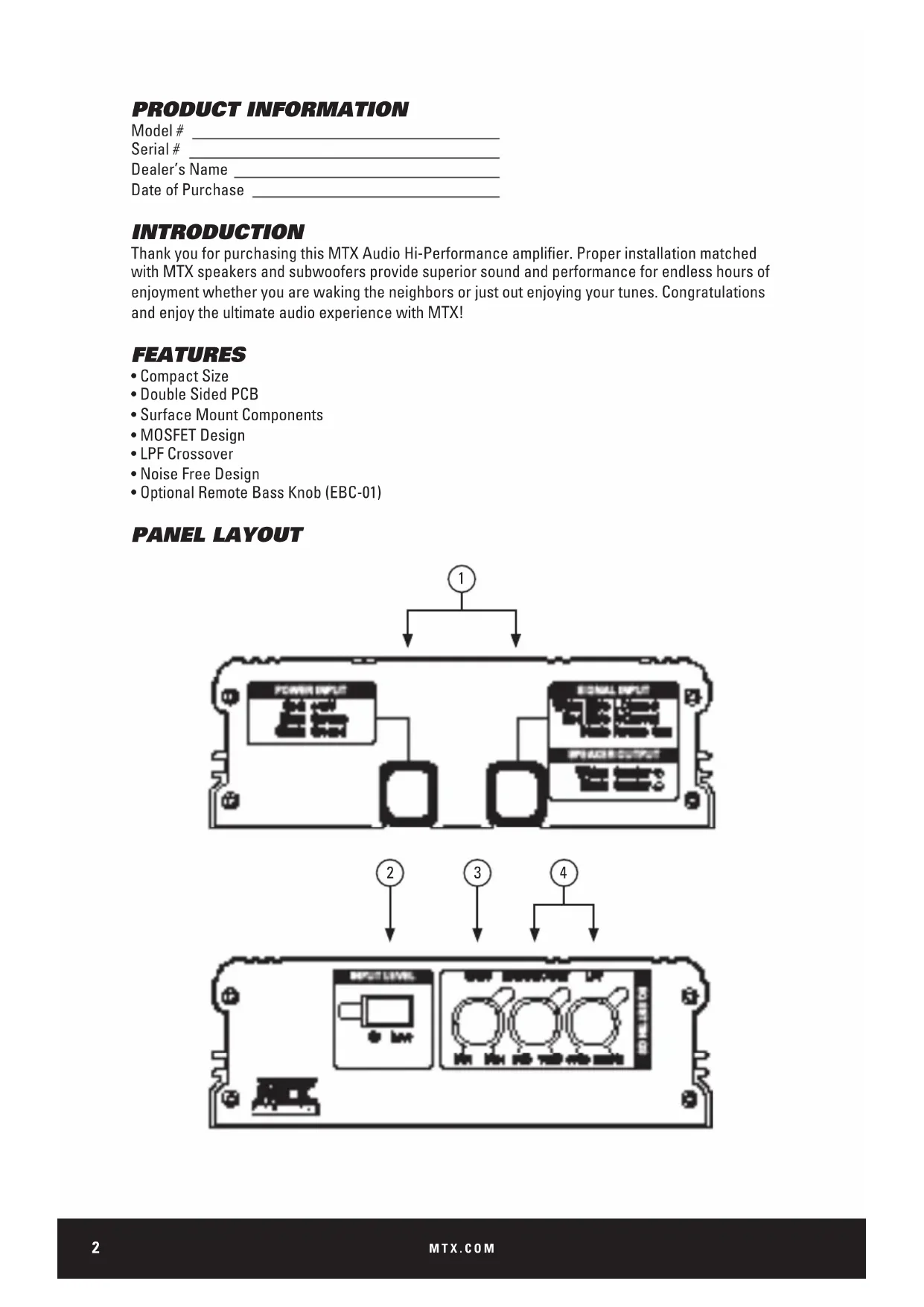
CONTROL FUNCTIONS
- Wiring Harness - All wiring to the amplifier will run through the wiring harness.
Speakers - Connect speakers/subwoofoers to these terminals. Be sure to check wire for proper polarity. Never connect the speaker cables to the chassis ground.
+BATT (+12 Volt Power) - Connect this terminal through a FUSE or CIRCUIT BREAKER to the positive terminal of the vehicle battery or the positive terminal of an isolated audio system
battery. WARNING: Always protect this power cable by installing a fuse or circuit breaker of the appropriate gauge within 18 inches (45cm) of the battery terminal connection.
Remote Turn On - This terminal turns on the amplifier when (+) 12 volt is applied to it. Connect it to the remote turn on lead of the head unit or signal source.
GND - Connect this cable directly to the frame of the vehicle. Make sure the metal frame has been stripped of all paint down to the bare metal. Use the shortest distance possible.
If a suitable ground point is not available on the frame, connect this terminal directly to the vehicle battery ground terminal, or any other factory ground points.
RCA Input Jacks - This unit is designed to function with source units that feature RCA outputs. If your source unit does not have RCA outputs you will need to use the speaker level inputs.
A source unit with a minimum level of 200mV is required for proper operation.
- Gain Control - The Gain control will match the amplifier's sensitivity to the source units signal voltage. The operating range is 10V to 200mV. NOTE: This is NOT a volume control.
- X-Over Mode - These controls allow control over the frequencies played. There is an option for Full, 80Hz, or 200Hz on the front channels, and an option for Full Range, High Pass, or Low Pass on the rear channels.
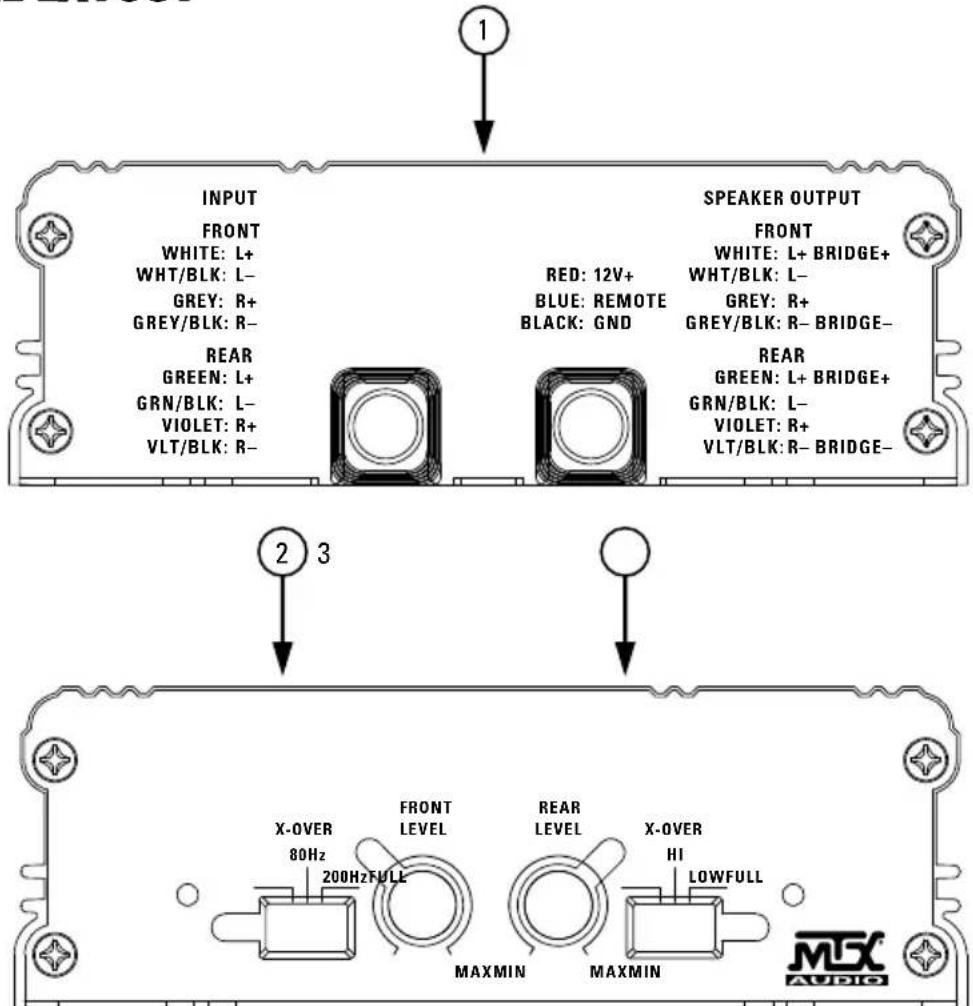
PANEL LAYOUT
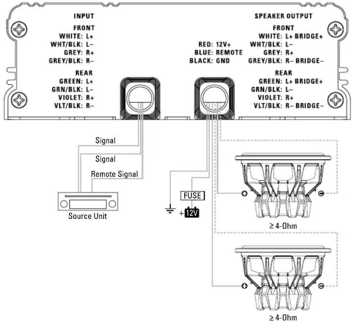
WIRING DIAGRAM
See page 22 for amplifier wiring diagrams.
INSTALLATION AND MOUNTING
MTX recommends your new Thunder Sports amplifier be installed by a 12 volt installation specialist. Any deviation from specified installation instructions can cause serious damage to the amplifier, speakers and/or vehicle's electrical system. Damage caused from improper installation is NOT covered under warranty. Please verify all connections prior to system turn on.
- Disconnect the vehicle's negative battery cable.
- Determine the mounting place for your MTX amplifier. Keep in mind there should be sufficient air flow for proper cooling. Mark the mounting holes from the amplifier to be drilled. Before drilling make sure all vehicle wires, gas lines, brake lines and gas tank are clear and will not interfere with installation. Drill the desired holes and mount the MTX amplifier.
- Install a positive (+) power cable from the vehicle's battery through the firewall using a grommet or firewall bushing to avoid cable damage from sharp edges of the firewall. Run the cable through the interior of the vehicle and connect it to the amplifier's +12V wire. Do not connect to the battery at this time. NOTE: Use only proper gauge wire for both positive and negative connections.
- Install a circuit breaker or fuse within 18 inches of the battery. This effectively lowers the risk of severe damage to you or your vehicle in case of a short circuit or accident. Make sure the circuit breaker is switched Off or the fuse is taken out of the fuse holder until all connections are made. Now connect your positive power cable to the positive battery terminal of the battery.
- Grounding - Locate a proper ground point on the vehicle's chassis and remove all paint, dirt or debris to reveal a bare metal surface. Attach the amplifier's ground wire to that contact point. If a suitable location is not available connect this terminal to the vehicle's negative battery terminal.
- Connect a Remote Turn-On wire from the source unit to the MTX amplifier's (REM) wire. If the source unit does not have a dedicated Remote Turn-On lead, you may connect to the source unit's Power Antenna lead.
- Supply the signal to your MTX amplifier by connecting the signal cables using high quality RCA or speaker wires to the corresponding outputs at the source unit and inputs of the amplifier.
- Connect your speakers to your MTX amplifier's speaker wires using the correct gauge speaker wire. Your MTX amp can drive a 2 stereo/4Ω bridged minimum load for optimum power.
- Double check all previous installation steps, in particular, wiring and component connections. Once verified, reconnect the vehicle's negative battery cable, turn the circuit breaker on or place the fuse in the fuse holder.
NOTE: Gain Levels on the amplifier should be turned all the way down (counter clockwise) before proceeding with adjustments.
INSTALLATION
For proper performance and safety, MTX recommends installing an inline fuse per the owner's manual instructions according to the following.
MUD100.4 30A Fuse
TROUBLESHOOTING
| Problem Cause Solution | ||
| Output Distorted | Head Unit Volume Set Too High Lower | Head Unit Volume |
| Amplifier Gain Set Too High Lower Amplifier Gain | ||
| Balance Reversed | Speaker Wire L & R Reversed Correct | Speaker Wire Orientation |
| RCA Inputs Reversed Reverse RCA Inputs | ||
| Bass is Weak | Speakers Wired Out of Phase Wire Speakers with Correct Phase | |
| Not Using MTX Subwooferbys Buy MTX Subwoofer | ||
| Blowing Fuses | Excessive Output Levels Lower the Volueme | |
| Amplifier Defective Return for Service | ||
SPECIFICATIONS
| Model MUD100.4 | |
| Description 50 W RMS/CH Stereo | |
| RMS Power at 14.4V | |
| 4Ω Bridged Load 200 W RMS | |
| 2Ω Load 100 W RMS | |
| 4Ω Load 50 W RMS | |
| Features | |
| Input Level 0.2 - 5V Low Level, 0.4 - 10V High Level | |
| Frequency Response 10Hz - 32 kHz | |
| Low Pass Filter (LPF) Rear Only 80Hz Fixed | |
| High Pass Filter (HPF) Rear 80Hz Fixed | |
| High Pass Filter (HPF) Front Selectable 80/200Hz | |
| THD at 4Ω, 1W <0.2% | |
| Signal-to-Noise Ratio >75dB | |
| Minimum Load 2Ω | |
| Low Voltage Protection Yes, Protect <8.5V | |
| Components & PCB | SMD Parts / Double Sided FR-4 PCB |
| Dimensions | |
| Height | 1.86" (47.2mm) |
| Width | 5.51" (140mm) |
| Length | 6.52" (165.5mm) |
INFORMACION DEL PRODUCTO
Numero de modelos
Numero de série
MUD100.4 Fusivel 30A
SOLUTION DE PROBLEMAS
INFORMATIONS SUR LE PRODUIT
Stereo 4Ω Front/4Ω Bridged Rear
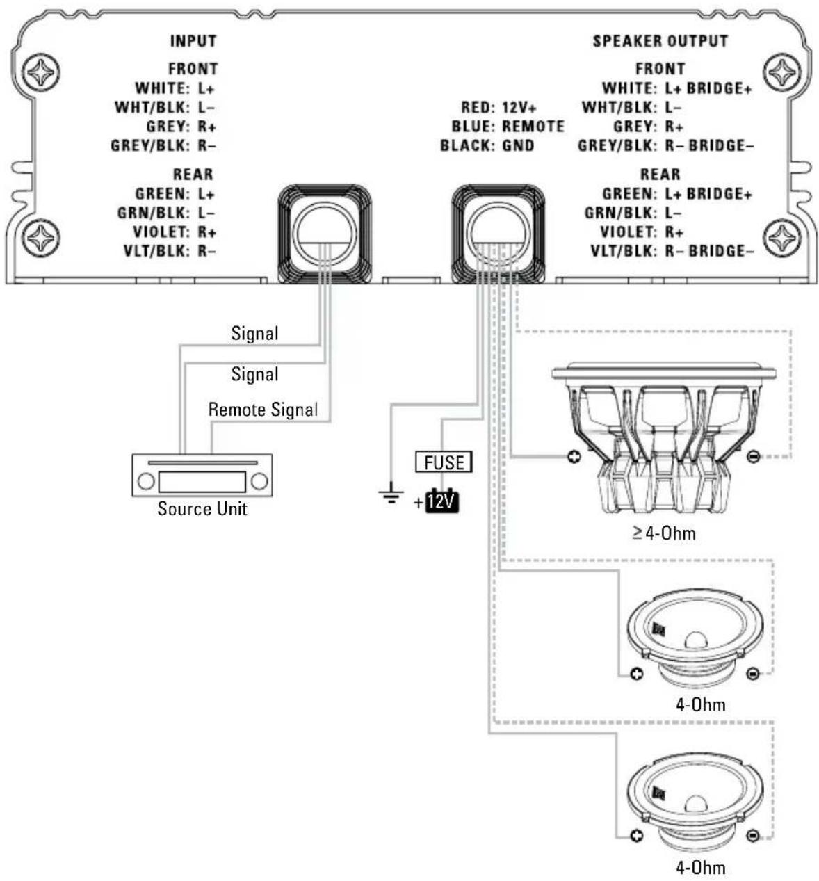
WIRING DIAGRAM
4Ω Bridged Subwoofer
NOTES:
NOTES:
© 2015 Mitek Corporation. All rights reserved. MTX is a trademark of Mitek Corporation. Designed and Engineered in the U.S.A.
Due to continual product development, all specifications are subject to change without notice.
MTX Audio, 4545 East Baseline Rd. Phoenix, AZ 85042 U.S.A.
MTX005172 RevA 4/15 • 21A10394 • AW0015062

N535
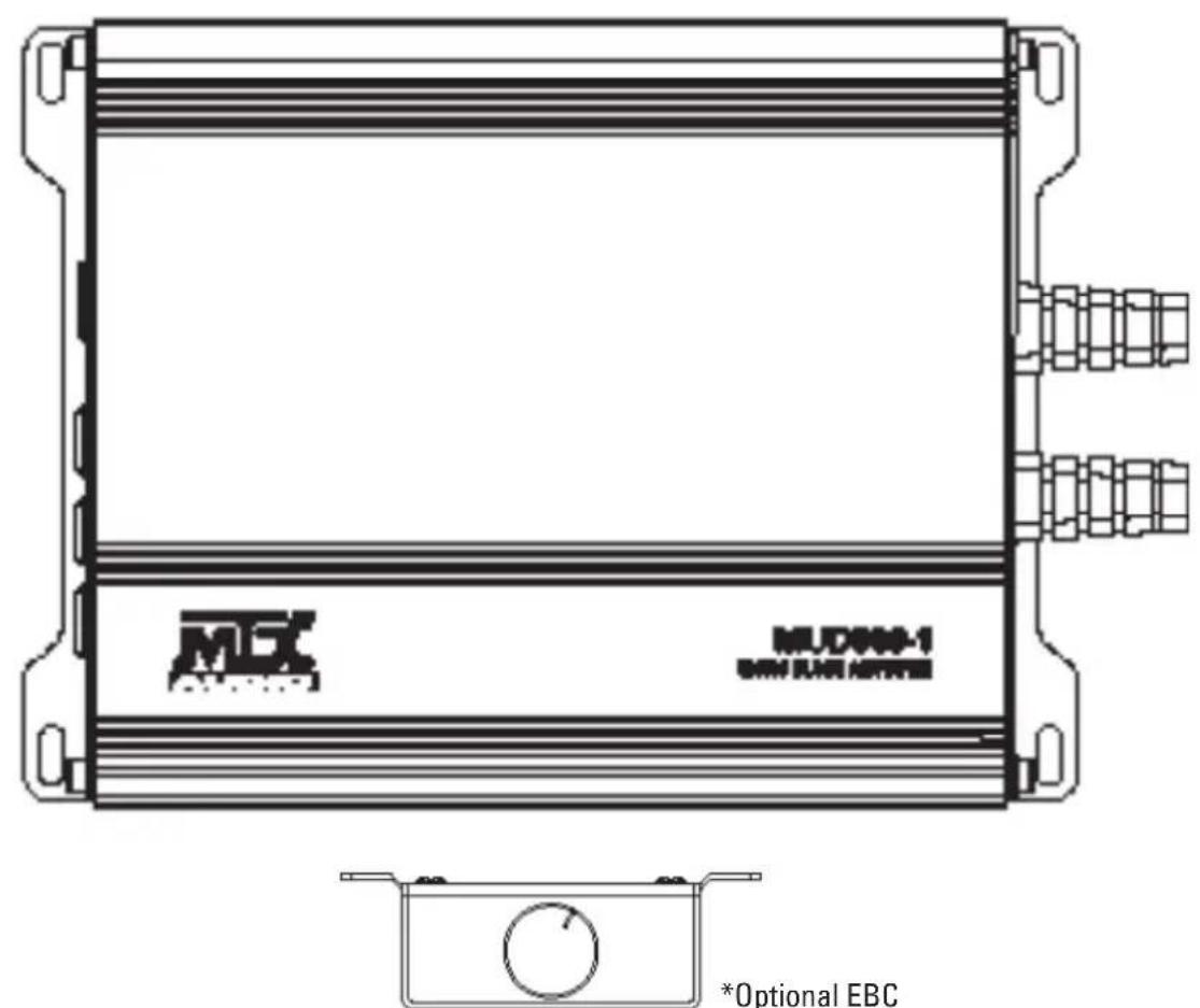
MUD600-1
MONO BLOCK AMPLIFIER
OWNER'S MANUAL
PRODUCT INFORMATION
Model#
Serial#
Dealer's Name
Date of Purchase
INTRODUCTION
Thank you for purchasing this MTX Audio Hi-Performance amplifier. Proper installation matched with MTX speakers and subwoofoers provide superior sound and performance for endless hours of enjoyment whether you are waking the neighbors or just out enjoying your tunes. Congratulations and enjoy the ultimate audio experience with MTX!
FEATURES
- Compact Size
Double Sided PCB - Surface Mount Components
MOSFET Design
LPFCrossover - Noise Free Design
- Optional Remote Bass Knob (EBC-01)
PANEL LAYOUT
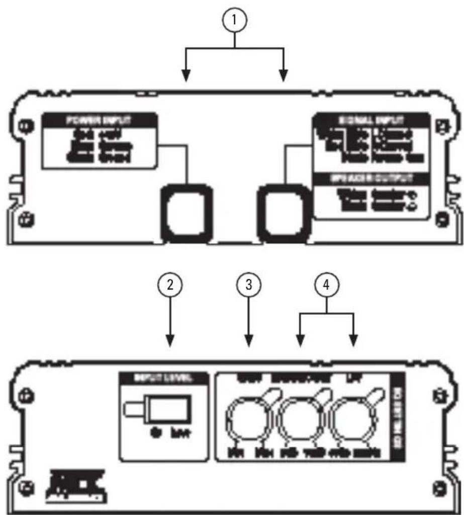
CONTROL FUNCTIONS
- Wiring Harness - All wiring to the amplifier will run through the wiring harnesses.
Speakers - Connect subwoofoers to these terminals. Be sure to check wire for proper polarity. Never connect the speaker cables to the chassis ground.
+BATT (+12 Volt Power) - Connect this terminal through a FUSE or CIRCUIT BREAKER to the positive terminal of the vehicle battery or the positive terminal of an isolated audio system
battery. WARNING: Always protect this power cable by installing a fuse or circuit breaker of the appropriate gauge within 18 inches (45cm) of the battery terminal connection.
Remote Turn On - This terminal turns on the amplifier when (+) 12 volt is applied to it. Connect it to the remote turn on lead of the head unit or signal source.
GND - Connect this cable directly to the frame of the vehicle. Make sure the metal frame has been stripped of all paint down to the bare metal. Use the shortest distance possible.
If a suitable ground point is not available on the frame, or if using in a marine or UTV application, connect this terminal directly to the vehicle battery ground terminal, or any other factory ground points.
RCA Input Jacks - This unit is designed to function with source units that feature RCA outputs. If your source unit does not have RCA outputs you will need to use the speaker level outputs. A source unit with a minimum level of 200mV is required for proper operation.
- Input Level - Allows switching the signal input mode from High (Speaker) level to Low (RCA) Level inputs.
- Gain Control - The Gain control will match the amplifier's sensitivity to the source units signal voltage. The operating range is 200mV to 10V. NOTE: This is NOT a volume control.
- Bass Boost / LPF - These controls allow control over the frequencies played. The Bass Boost allows adjustment of up to 18dB of boost to be applied at 45Hz. The LPF controls the built in Low Pass Crossover cut-off frequency between 40Hz~250Hz.
WIRING DIAGRAM
See page 22 for amplifier wiring diagrams.
INSTALLATION AND MOUNTING
MTX recommends your new amplifier be installed by a 12 volt installation specialist. Any deviation from specified installation instructions can cause serious damage to the amplifier, speakers and/or vehicle's electrical system. Damage caused from improper installation is NOT covered under warranty. Please verify all connections prior to system turn on.
- Disconnect the vehicle's negative battery cable.
- Determine the mounting place for your MTX amplifier. Keep in mind there should be sufficient air flow for proper cooling. Mark the mounting holes from the amplifier to be drilled. Before drilling make sure all vehicle wires, gas lines, brake lines and gas tank are clear and will not interfere with installation. Drill the desired holes and mount the MTX amplifier.
- Install a positive (+) power cable from the vehicle's battery through the firewall using a grommet or firewall bushing to avoid cable damage from sharp edges of the firewall. Run the cable through the interior of the vehicle and connect it to the amplifier's +12V wire. Do not connect to the battery at this time. NOTE: Use only proper gauge wire for both positive and negative connections.
- Install a circuit breaker or fuse within 18 inches of the battery. This effectively lowers the risk of severe damage to you or your vehicle in case of a short circuit or accident. Make sure the circuit breaker is switched Off or the fuse is taken out of the fuse holder until all connections are made. Now connect your positive power cable to the positive battery terminal of the battery.
- Grounding - Locate a proper ground point on the vehicle's chassis and remove all paint, dirt or debris to reveal a bare metal surface. Attach the amplifier's ground wire to that contact point. If a suitable location is not available or if using in a marine or UTV application, connect this terminal to the vehicle's negative battery terminal.
- Connect a Remote Turn-On wire from the source unit to the MTX amplifier's (REM) wire. If the source unit does not have a dedicated Remote Turn-On lead, you may connect to the source unit's Power Antenna lead.
- Supply the signal to your MTX amplifier by connecting the signal cables using high quality RCA or speaker wires to the corresponding outputs at the source unit and inputs of the amplifier.
- Connect your speakers to your MTX amplifier's speaker wires using the correct gauge speaker wire. Your MTX amp can drive a 2 mono minimum load for optimum power.
- Double check all previous installation steps, in particular, wiring and component connections. Once verified, reconnect the vehicle's negative battery cable, turn the circuit breaker on or place the fuse in the fuse holder.
NOTE: Gain Levels on the amplifier should be turned all the way down (counter clockwise) before proceeding with adjustments.
INSTALLATION
For proper performance and safety, MTX recommends installing an inline fuse per the owner's manual instructions according to the following.
MUD600-1 60A Fuse
TROUBLESHOOTING
| Problem Cause Solution | ||
| Output Distorted | Head Unit Volume Set Too High Lower | Head Unit Volume |
| Amplifier Gain Set Too High Lower Amplifier Gain | ||
| Bass is Weak | Speakers Wired Out of Phase Wire Speakers with Correct Phase | |
| Not Using MTX Subwoofoers Buy MTX Subwoofoers | ||
| Blowing Fuses | Excessive Output Levels Lower the Volume | |
| Amplifier Defective Return for Service | ||
For MTX technical support please call 1 (800) 225-5689 or chat with us online at mtx.com
SPECIFICATIONS
| Model MUD600-1 | |
| Description Class D Mono Amplifier | |
| Primary Ratings* | |
| Primary Power | 300 W RMS at 4Ω, 20-165Hz and ≤ 1% THD+N* |
| Signal-to-Noise Ratio 85 dBA | |
| Secondary Ratings* | |
| Dynamic Power | 425 W at 4Ω, ≤ 1% THD+N 650 W at 2Ω, ≤ 1% THD+N |
| Features | |
| Input Level 0.2 - 5V Low Level, 0.4 - 10V High Level | |
| Frequency Response 10Hz - 250 Hz | |
| Low Pass Filter (LPF) 40-250Hz Variable | |
| Minimum Load 2Ω | |
| Low Voltage Protection Yes, Protect <8.5V | |
| Components & PCB SMD Parts / Double Sided FR-4 PCB | |
| Dimensions | |
| Height 1.85" (47mm) | |
| Width 5.51" (140mm) | |
| Length 7.36" (187mm) | |
*Amplifier ratings in accordance with CTA-2006C standards.
INFORMACION DEL PRODUCTO
Numero de modelos
Numero de série
INFORMATIONS SUR LE PRODUIT
Modèle
© 2019 Mitek Corporation. All rights reserved. MTX, Mud Nation, and Let's Do Something Dirty are trademarks of Mitek Corporation. All other trademarks are property of their respective owners. Designed and Engineered in the U.S.A.
Due to continual product development, all specifications are subject to change without notice.
MTX Audio, 4545 East Baseline Rd. Phoenix, AZ 85042 U.S.A. 1-800-225-5689
MTX005930 RevA 2/19 • 21A10713 • AW0015728

N535
MEX AUDIO
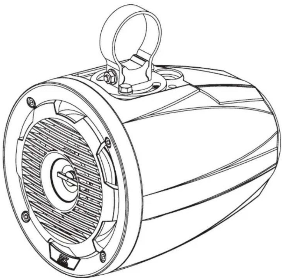
MUD65PL
CAGE MOUNT SPEAKER WITH RGB LEDs
OWNER'S MANUAL

THANK YOU
Thank you for making the AWESOME decision to purchase our MTX Audio cage mount speaker pod. This high performance speaker features all-weather construction designed to deliver exceptional sound quality and volume for high output systems for those that love to hear their music wherever they are. Additionally, each speaker enclosure includes a RGB LED light kit that enables customization of the speaker lighting color on the grille. So, what are you waiting for? It's time to get the rumble in your ride and go hit the trails! Oh, and congratulations on your purchase, thanks for your support and most importantly, enjoy the ultimate audio experience with MTX!
WE'RE HERE TO HELP
We're here to help with any installation or technical support. Visit mtx.com to chat, call 1-800-225-5689 to speak with an MTX Technical Support representative, or visit youtube.com/user/MTXAudioUSA to view product videos.
DON'T FORGET TO REGISTER YOUR PRODUCT
Don't forget to register your new MTX Audio product. Visit mtx.com/productregistration or scan the QR code to the right.
Model #
Serial#
Dealer's Name
Date of Purchase

IMPORTANT NOTICE
Whenever working on the vehicle, it is recommended to disconnect the battery prior to starting work. Failure to do so may lead to a risk of electric shock or equipment damage.
When connecting power and ground wires ensure that the red power wire is fused at the point where it is connected to the vehicle's battery. Failure to do so can result in damage to the vehicle if a short circuit develops between the vehicle connection point and the product.
FEATURES
- Integrated RGB LED Lighting
- Includes Rotating Brackets for 1.75", 1.85", and 2" Bars
- ABS Impact Resistant Enclosure and Grille with UV Inhibitor
- Polypropylene Woofer and Mylar Dome Tweeter
SPECIFICATIONS
RMS Power Handling: 50-Watts
Peak Power Handling: 100-Watts
- Sensitivity (2.83V/1m): 89.9dB
Sensitivity (1W / 1m) :85.6dB
Frequency Response: 70Hz - 20kHz
Impedance: 4Ω
- Fits Bars 1.75", 1.85", and 2"
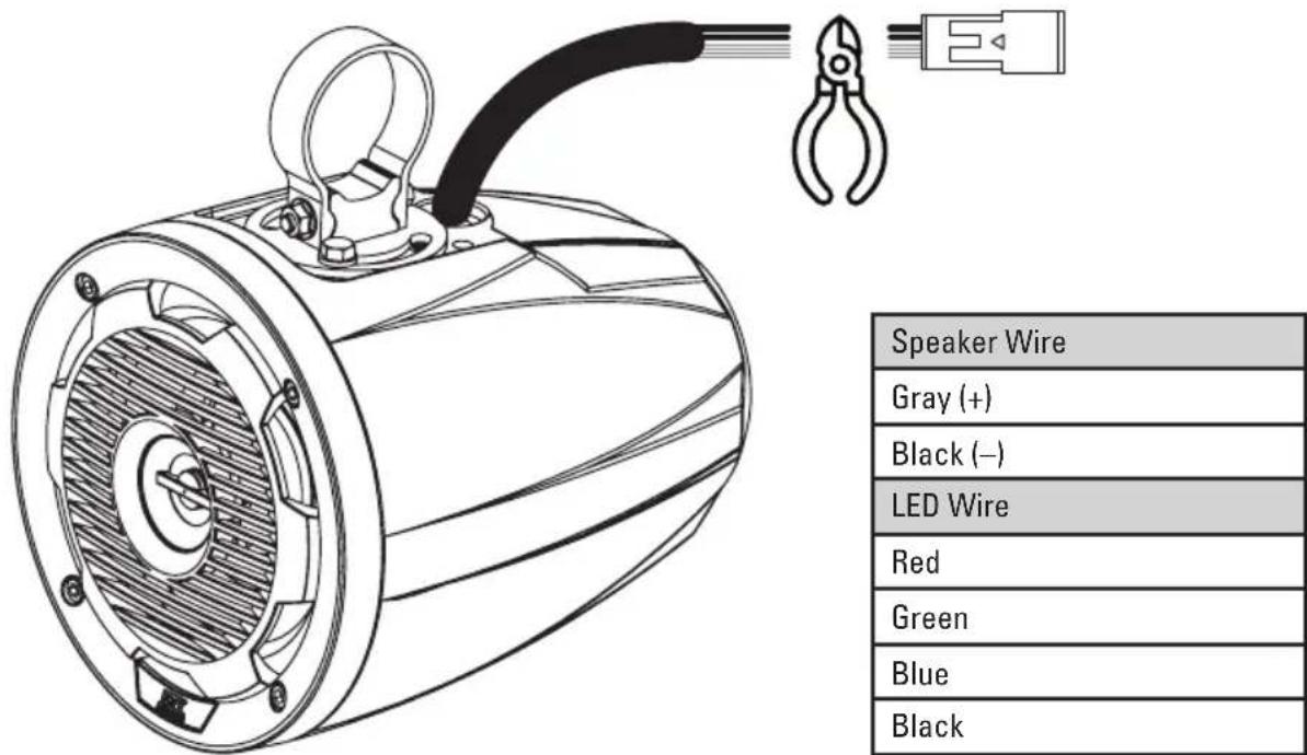
WIRE COLOR
- Grey/Black: +/- speaker wire
- Black / Red / Green / Blue: +/ground speaker illumination
IN THE BOX
- Speaker and Enclosure
-
Brackets
-
For Mounting the Bracket Base to the Enclosure
(8) M6-1.0x14mm Stainless Steel Hex Bolt
(8) M6 Stainless Steel Flat Washer
(8) M6 Stainless Steel Split Lock Washer
- For Tightening the Bracket Strap to the Base
(2) M6-1.0x50mm Stainless Steel Hex Bolt
(2) M6 Stainless Steel Serrated Flange Lock Nut
INSTALLATION
- Choose appropriate bracket clamp, 1.75", 1.85", and 2", for the application. If using the MUD65PL with a ProFit or Profile style enclosure, use optional bracket MUDPFC, to attach speaker enclosure to cage.
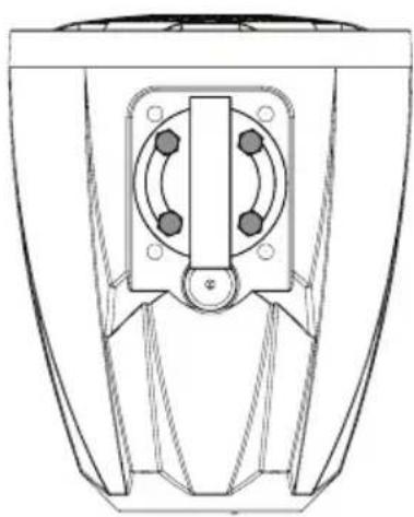
- Attach bracket base to enclosure at desired angle using a minimum of two (2) M6-1.0x14mm Hex bolts and M6 lock washers. If only two (2) bolts are used, ensure there is a bolt on each side of the round base for secure mounting.
- Slide bracket clamp over pipe or bar at desired mounting location.
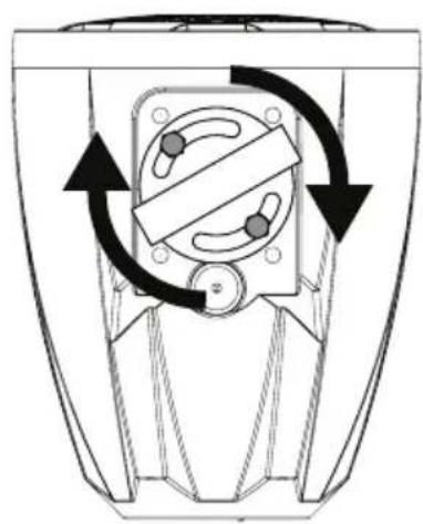
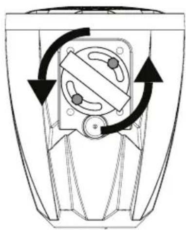
- Hold the enclosure in place where the base fits in the open section of the clamp. Then place the M6-1.0x50mm Hex bolt through making sure the threads are towards the front of the enclosure. See Figure 1.
- Tighten the M6 serrated nut onto the bolt until the bracket is tight. The nut is serrated and will lock in place. The speaker will not rotate on the bar if it is mounted when these are fully tightened.
- Adjust and tighten the bolts to the desired position making sure to use a minimum of two bolts. Depending on the position of the speaker, only two (2) insertion points will be usable.
- Attach the MTX badge to the rear recess of the enclosure with the included double stick tape.
- Connect the speaker wires to your amplifier ensuring correct polarity Grey to positive and Black to negative. The MUD65PL includes speaker illumination. When hard-wiring the RGB lighting, the Black lead is +12V and the Red, Green, and Blue leads are ground. There are seven colors available, depending on the wiring configuration. MTX recommends using the MUDLEDC remote control (sold separately) for more colors, patterns and special effects. See Figure 2.
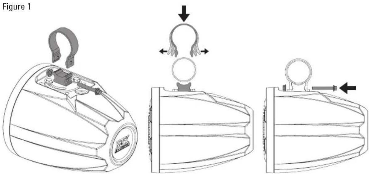
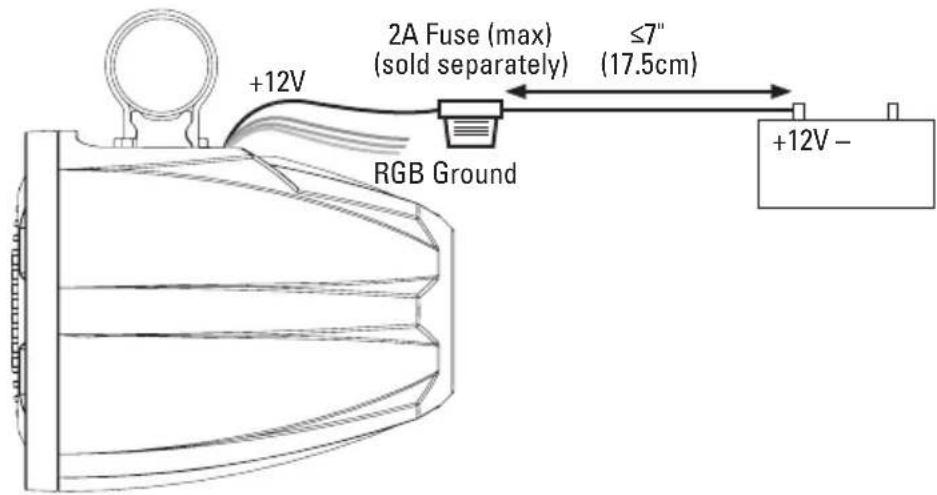
Figure 2
| Color Combinations: Splice and combine the ground wires to yeild a different color. | |
| Red Red | |
| Green Green | |
| Blue Blue | |
| Red / Green Lime Green | |
| Red / Blue Magenta | |
| Green / Blue Aquamarine | |
| Red / Green / Blue Blue-White | |
MUD65PL UNIVERSAL UTV AUDIO KIT INSTALLATION
The MTX Audio MUD65PL coaxial speaker pods come factory equipped with a wiring plug that is specifically designed to pair with our Vehicle Specific Thunder Audio Kits. If using the MUD65PL in a Universal Kit or individually, the wiring plug must be removed from the MUD65PL and the speaker simply hardwired into the system.
The bracket base can rotate in any direction desired, a minimum of 2 bolts must be used, 1 on each side.
WARRANTY PERIOD
At MTX Audio we engineer products that will stand up to the test of time. We also realize that from time to time a problem may occur. That's why our products carry a 2-year limited warranty that begins at the time of sale to the end user.
Of course, we're here to help. If you experience an issue with any of our products within the warranty period, please contact our customer service technical line at 1-800-CALL-MTX to help troubleshoot your issue. If, after speaking with our technical experts it is determined that a problem lies with the product, the technician will provide you with a Return Authorization number and all relevant details you'll need to get the product taken care of.
MITEK WARRANTY
MiTek Mobile products (including, but not limited to: MTX, Coustic, Streetwires, Xtant, BassSlammer, and Thunder Marine) purchased in the USA from an AUTHORIZED MITEK DEALER are guaranteed against defects in material and workmanship for the period of time specified. The warranty period begins the day the product is purchased by the end user, and this warranty is limited to the original retail purchaser of product. Products found to be defective during the warranty period will be repaired or replaced with equivalent product by MiTek at no charge. This warranty is void if it is determined that unauthorized parties have attempted repairs or alterations of any nature, and the warranty does not extend to cosmetics or finish. MiTek disclaims any liability for other incurred or consequential damages resulting from product defects. MiTek's total liability will not exceed the purchase price of the product.

Let's Get Social mtx.com

Like, Follow, & Subscribe
© 2020 MiTek Corporation. All rights reserved. MTX is a trademark of MiTek Corporation. All other trademarks are property of their respective owners. Designed and Engineered in the U.S.A.
Due to continual product development, all specifications are subject to change without notice.
MTX Audio, 4545 East Baseline Rd. Phoenix, AZ 85042 U.S.A. 1-800-225-5689
MTX005835 RevB 11/20 • 21A10844 • AW0015909

RZR-14-FS
POLARIS® RZR® FRONT SPEAKER PODS
OWNER'S MANUAL
THANK YOU
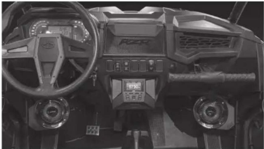
Thank you for making the AWESOME decision to purchase our MTX Audio 6.5" weatherproof kick panel speakers for your Polaris® RZR®. With a few simple tools from your trusty toolbox, these speakers are so easy to install that even a 5-year old can do it. Trust us when we say we've tried it. The rotationally molded enclosures are built as a single piece, designed to take years of abuse without failure and the Quick Install Bracket with POD-LOC technology makes mounting them a snap, literally. And of course, who can forget the integrated RGB lighting in the speakers, because, who doesn't like things that light up, right? So, congratulations on your purchase, thanks for your support and most importantly, enjoy the ultimate audio experience with MTX!
WE'RE HERE TO HELP
We're here to help with any installation or technical support. Visit mtx.com to chat, call 1-800-225-5689 to speak with an MTX Technical Support representative, or visit youtube.com/user/MTXAudioUSA to view product videos.
DON'T FORGET TO REGISTER YOUR PRODUCT
Don't forget to register your new MTX Audio product. Visit mtx.com/productregistration or scan the QR code to the right.
Model #
Serial #
Dealer's Name
Date of Purchase

MAKE SURE TO READ THIS
If the RZR-14-FS kick panel speaker pods are being installed along with the RZR-14-SW subwoofer enclosure, the subwoofer MUST be installed first.
IMPORTANT NOTICE
Whenever working on the vehicle, it is recommended to disconnect the battery prior to starting work. Failure to do so may lead to a risk of electric shock or equipment damage.
When connecting power and ground wires ensure that the red power wire is fused at the point where it is connected to the vehicle's battery. Failure to do so can result in damage to the vehicle if a short circuit develops between the vehicle connection point and the product.
FEATURES
- Integrated RGB LED Lighting
- Custom Fit for RZR® Kick Panel
- Custom Quick Mount Bracket with POD-LOC Technology for Easy Installation
- Rotationally Molded Sealed Enclosure
Factory Matched Texture - Polypropylene Woofer and Mylar Dome Tweeter
- Installer Friendly Design
- Direct Fit, No Cutting or Drilling Required
SPECIFICATIONS
RMS Power Handling: 50-Watts
Peak Power Handling: 100-Watts
- Sensitivity (2.83V/1m): 89.9dB
Sensitivity (1W / 1m) :85.6dB
Frequency Response: 70Hz - 20kHz
Impedance: 4Ω
FIT GUIDE
RZR 900 2014-2020
RZR 900 XC 2015-2020
RZR 2 900 EPS 2014 - 2018
RZR 4 900 EPS. 2014 - 2020
RZR S 900. 2014 - 2020
RZR S 1000. 2017 - 2020
RZR S4 1000 2019-2020
RZR XP 1000 2014-2020
RZR XP Turbo 2016-2020
RZR XP Turbo S. 2019 - 2020
RZR XP Turbo Dynamix Edition 2018 - 2020
RZR XP 4 1000 2014 - 2020
RZR XP 4 Turbo . 2016 - 2020
RZR XP 4 Turbo S. 2019 - 2020
RZR XP 4 Turbo Dynamix Edition 2018 - 2020
RZR XP 1000 Trails and Rocks. 2019 - 2020
RZR XP 1000 High Lifter. 2014 - 2020
RZR XP 4 1000 High Lifter. 2014 - 2020
IN THE BOX
RZR-14-FS Kick Panel Speaker Pods (Left and Right Enclosures)
- Mounting Hardware
(2) Mounting Brackets
(2) 10mm Screws
INSTALLATION
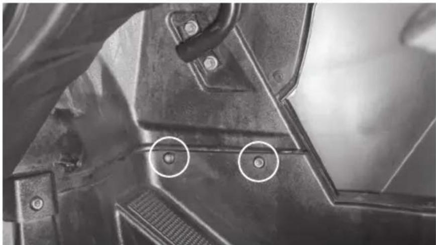
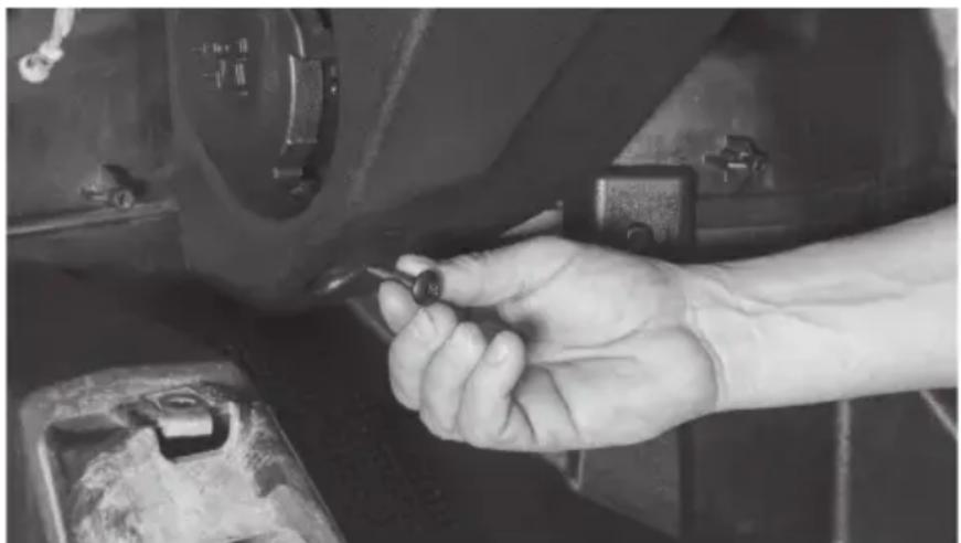
Step 1 - Remove the two (2) T40 screws at the bottom of the kick panel.
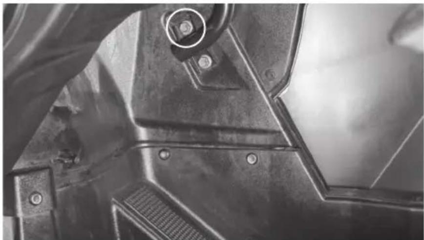
Step 2 - Remove the top 13mm body bolt.
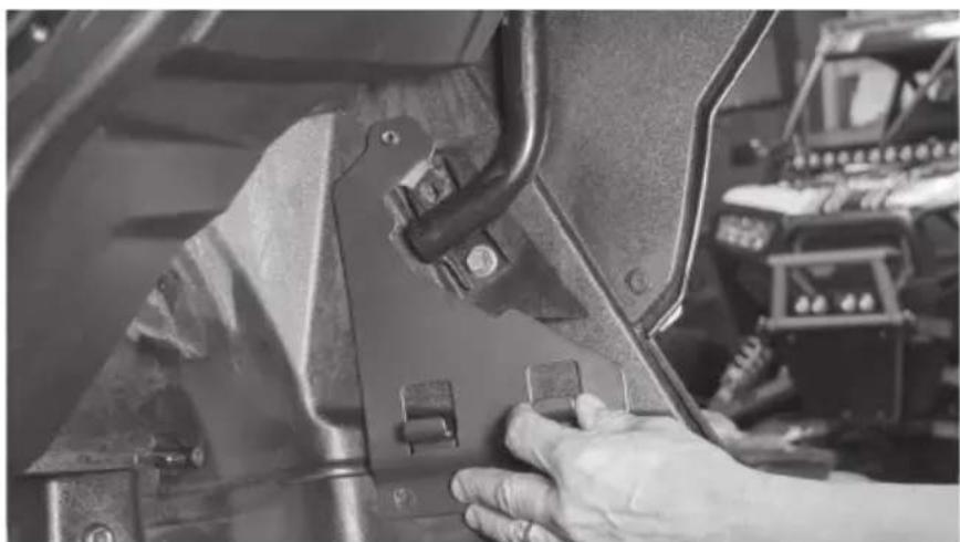
Step 3 - Place the custom quick mount speaker bracket.
Step 4 - Reinstall the body bolt and two (2) T40 screws.
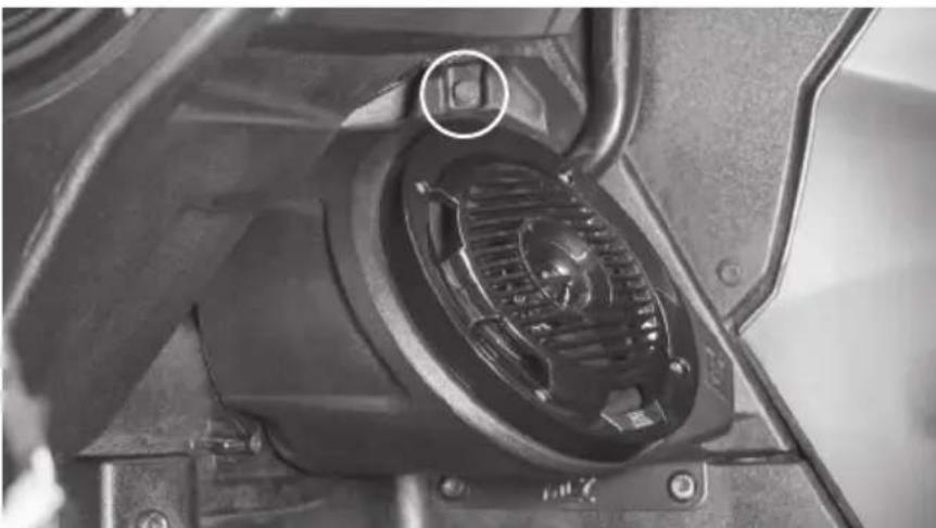
Step 5 - Align the bottom of the RZR-14-FS speaker pod with the hooks on the custom quick mount speaker bracket. Tilt the top of the speaker pod toward the outer body until flush against the mounting bracket. Push down until the pod locks in place.
Step 6 - Align the top of the speaker pod with the speaker bracket and insert the supplied 10mm bolt.
Step 7 - Feed wire into dash towards amplifier mounting location. Note: In the event these are not used with an MTX THUNDER SYSTEM, it will be necessary to cut off the connectors and hardwire directly to your equipment.
Step 8 - Reassemble and go ride.
WARRANTY PERIOD
At MTX Audio we engineer products that will stand up to the test of time. We also realize that from time to time a problem may occur. That's why our products carry a 2-year limited warranty that begins at the time of sale to the end user.
Of course, we're here to help. If you experience an issue with any of our products within the warranty period, please contact our customer service technical line at 1-800-CALL-MTX to help troubleshoot your issue. If, after speaking with our technical experts it is determined that a problem lies with the product, the technician will provide you with a Return Authorization number and all relevant details you'll need to get the product taken care of.
MITEK WARRANTY
Mitek Mobile products (including, but not limited to: MTX, Coustic, Streetwires, Xtant, BassSlammer, and Thunder Marine) purchased in the USA from an AUTHORIZED MITEK DEALER are guaranteed against defects in material and workmanship for the period of time specified. The warranty period begins the day the product is purchased by the end user, and this warranty is limited to the original retail purchaser of product. Products found to be defective during the warranty period will be repaired or replaced with equivalent product by Mitek at no charge. This warranty is void if it is determined that unauthorized parties have attempted repairs or alterations of any nature, and the warranty does not extend to cosmetics or finish. Mitek disclaims any liability for other incurred or consequential damages resulting from product defects. Mitek's total liability will not exceed the purchase price of the product.

Let's Get Social mtx.com

Like, Follow, & Subscribe
© 2020 Mitek Corporation. All rights reserved. MTX is a trademark of Mitek Corporation. All other trademarks are property of their respective owners. Designed and Engineered in the U.S.A.
Due to continual product development, all specifications are subject to change without notice.
MTX Audio, 4545 East Baseline Rd. Phoenix, AZ 85042 U.S.A. 1-800-225-5689
MTX006072 RevA 2/20 • 21A10764 • AW0015797

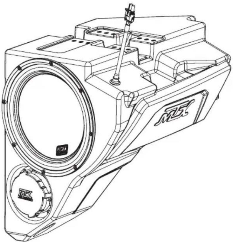
RZR-14-SW
POLARIS® RZR® SUBWOOFER ENCLOSURE
OWNER'S MANUAL

THANK YOU
Congratulations and thank you for purchasing the MTX Audio direct-fit subwoofer enclosure designed for the Polaris® RZR®. Our sub enclosure, with its high output 10" subwoofer, will belt out the bass and deliver ground pounding audio making you the party vehicle in any ride! With a few basic hand tools in your trusty toolbox, you can have this installed in no time. So, what are you waiting for? It's time to get the rumble in your ride and go hit the trails! Oh, and congratulations on your purchase, thanks for your support and most importantly, enjoy the ultimate audio experience with MTX!
WE'RE HERE TO HELP
We're here to help with any installation or technical support. Visit mtx.com to chat, call 1-800-225-5689 to speak with an MTX Technical Support representative, or visit youtube.com/user/MTXAudioUSA to view product videos.
DON'T FORGET TO REGISTER YOUR PRODUCT
Don't forget to register your new MTX Audio product. Visit mtx.com/productregistration or scan the QR code to the right.
Model #
Serial#
Dealer's Name
Date of Purchase

MAKE SURE TO READ THIS
Installation of this enclosure will delete the factory supplied glove box.
If the RZR-14-SW subwoofer enclosure is being installed along with the RZR-14-FS kick panel speaker pods, the subwoofer must be installed first.
The Quick Install Port Seal cap allows the enclosure to be used as a sealed system. For maximum bass, we recommend removing the cap for normal operation but keeping it in the vehicle. In the event of a deep water or submersion situation, the cap can quickly be reinstalled to prevent water penetration into the enclosure.
IMPORTANT NOTICE
Whenever working on the vehicle, it is recommended to disconnect the battery prior to starting work. Failure to do so may lead to a risk of electric shock or equipment damage.
When connecting power and ground wires ensure that the red power wire is fused at the point where it is connected to the vehicle's battery. Failure to do so can result in damage to the vehicle if a short circuit develops between the vehicle connection point and the product.
FEATURES
- Can Be Used as a Ported or Sealed Enclosure
- Includes an MTX 55 Series Subwoofer for its Deep Bass Reproduction Capabilities
- QuIPS (Quick Install Port Seal) Technology
- Mounts Behind Dashboard
Factory Matched Texture - Installer Friendly Design
- Direct Fit, No Cutting or Drilling Required
SPECIFICATIONS
- 10" Loaded Subwoofer Enclosure
RMS Power Handling: 400-Watts
Peak Power Handling: 800-Watts - Sensitivity (2.83V/1m): 90.2dB
- Sensitivity (1W/1m): 83.5dB
Frequency Response: 28Hz - 130Hz
Impedance: Dual 4Ω
FIT GUIDE
RZR 900 2014-2020
RZR 900 XC 2015-2020
RZR 2 900 EPS 2014 - 2018
RZR 4 900 EPS 2014 - 2020
RZR S 900. 2014 - 2020
RZR S 1000. 2017 - 2020
RZR S4 1000 2019-2020
RZR XP 1000 2014 - 2020
RZR XP Turbo 2016-2020
RZR XP Turbo S. 2019 - 2020
RZR XP Turbo Dynamix Edition 2018 - 2020
RZR XP 4 1000 2014 - 2020
RZR XP 4 Turbo 2016-2020
RZR XP 4 Turbo S. 2019 - 2020
RZR XP 4 Turbo Dynamix Edition 2018 - 2020
RZR XP 1000 Trails and Rocks. 2019 - 2020
RZR XP 1000 High Lifter. 2014 - 2020
RZR XP 4 1000 High Lifter. 2014 - 2020
FITGUIDENOTES
Kits featuring a subwoofer are not compatible with Polaris® heater option (located where the subwoofer enclosure should fit).
IN THE BOX
RZR-14-SW Loaded Subwoofer Enclosure
- Mounting Hardware
(2) Mounting Brackets
(6) 10mm Screws
(1) T40 Torx Screw
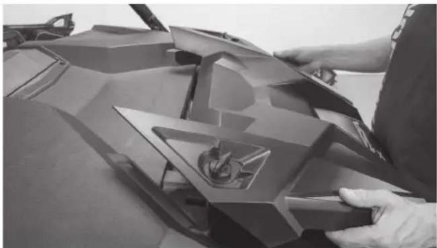
DISASSEMBLY - RZR MODELS 2019+
Step 1 - Release the two quick locks to remove the hood from the vehicle. Lift the hood and slide it towards the front of the vehicle
Step 2 - Remove the four (4) T40 screws holding down the top dash cover.
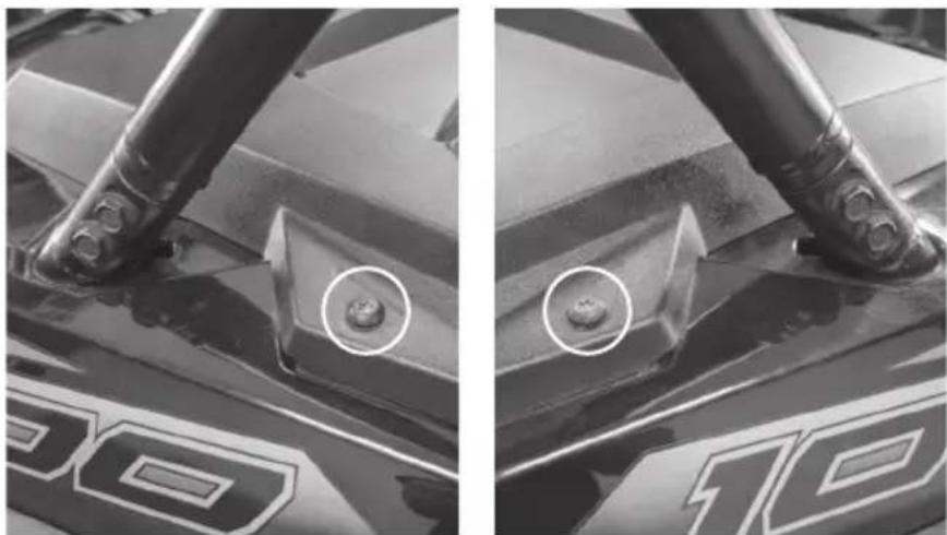
Driver Side Passenger Side
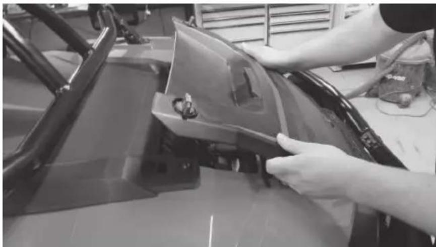
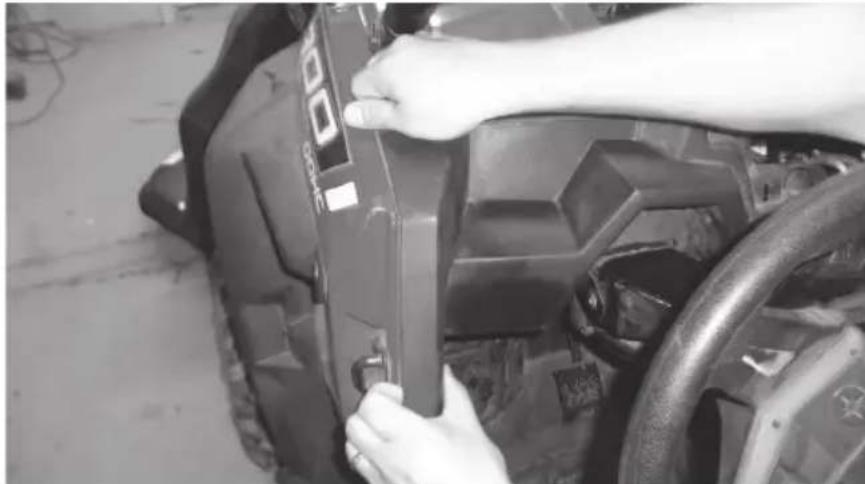
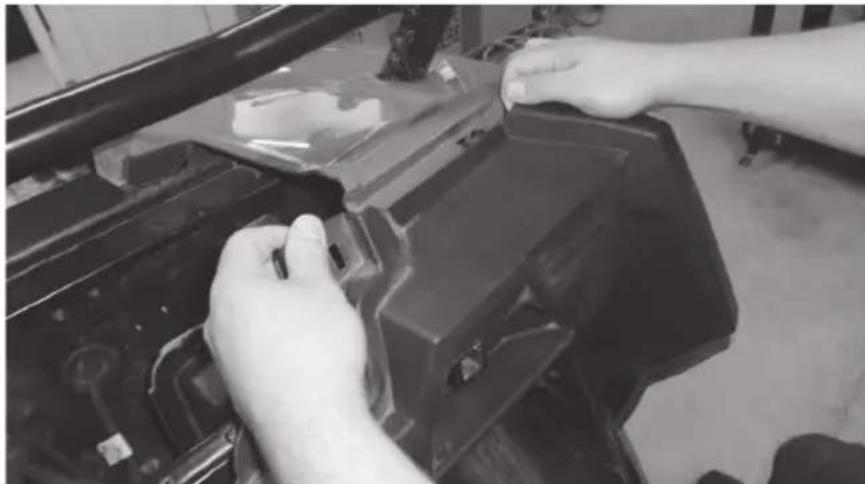
Step 3 - Remove the retaining clips holding the center dash compartment in place. Remove the compartment.
Step 4 - Remove the dash top panel.
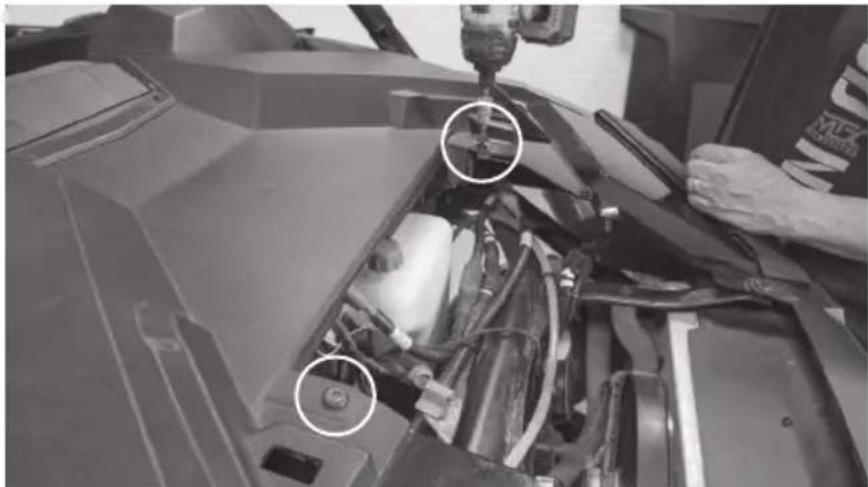
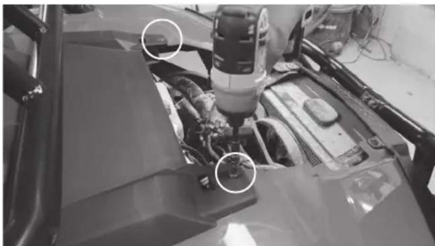
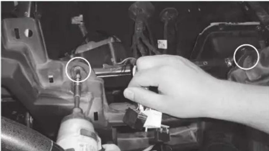
Step 5 - Remove the two (2) bolts in the center behind the dash. Note: For vehicles with Ride Command units, you may find two additional bolts on either side of the display. Remove these if present.
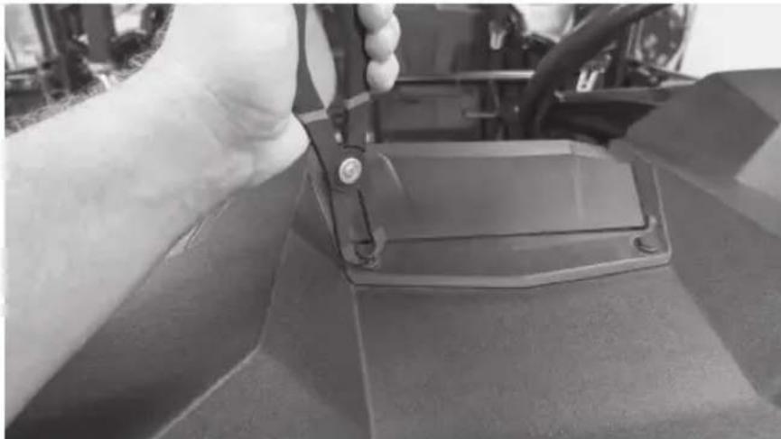
Step 6 - Remove the T-handle and clip.
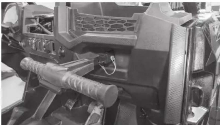
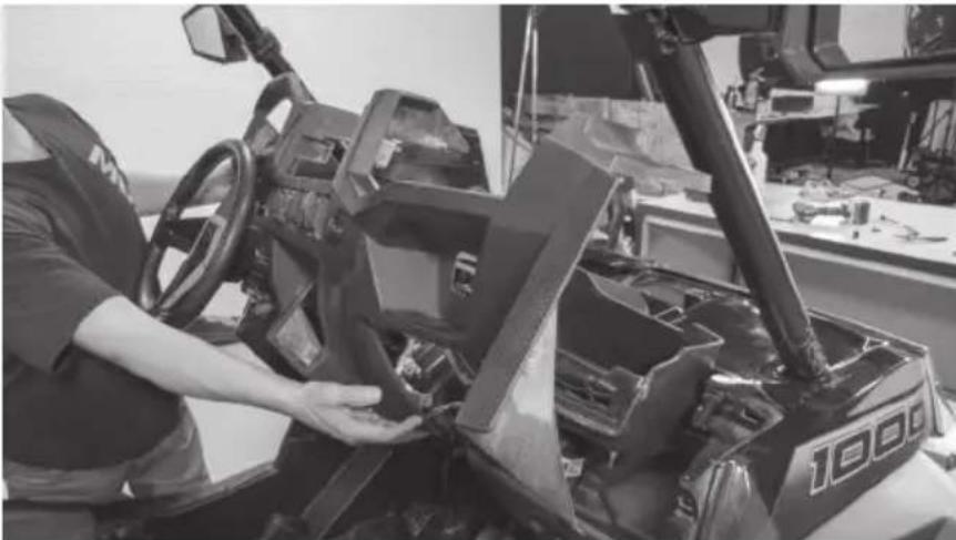
Step 7 - Remove the Torx head screw from the dash pocket brace. After this is removed the plastic dash pocket can be pulled out of the dash.
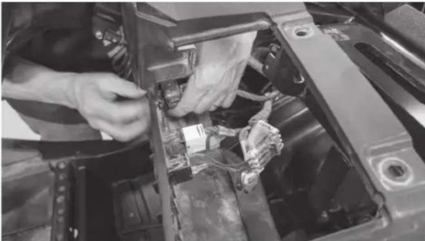
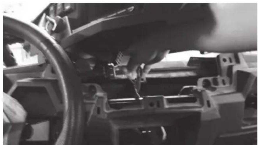
Step 8 - Unplug the gauge and switches making sure not to damage the vehicle and ignition wiring. Make note to remember what connector is associated with each specific switch.
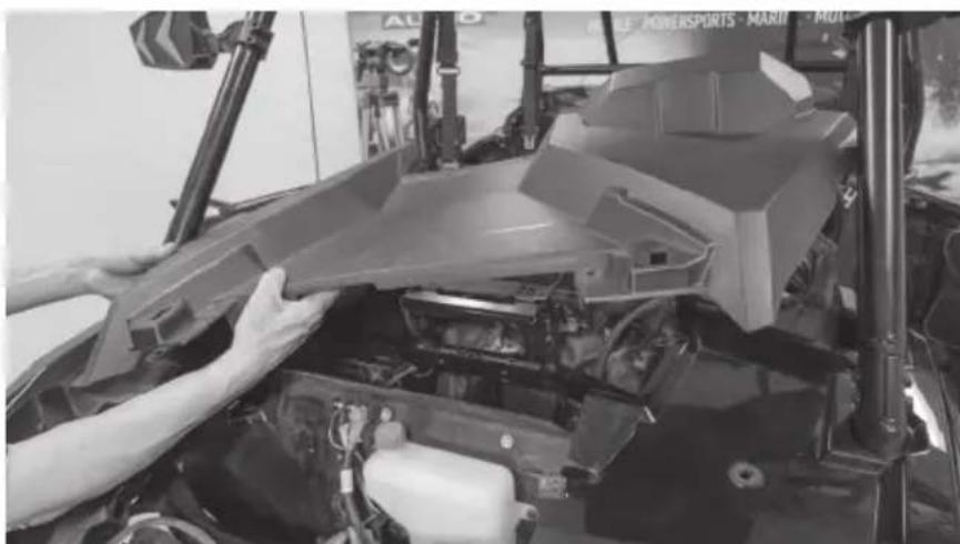
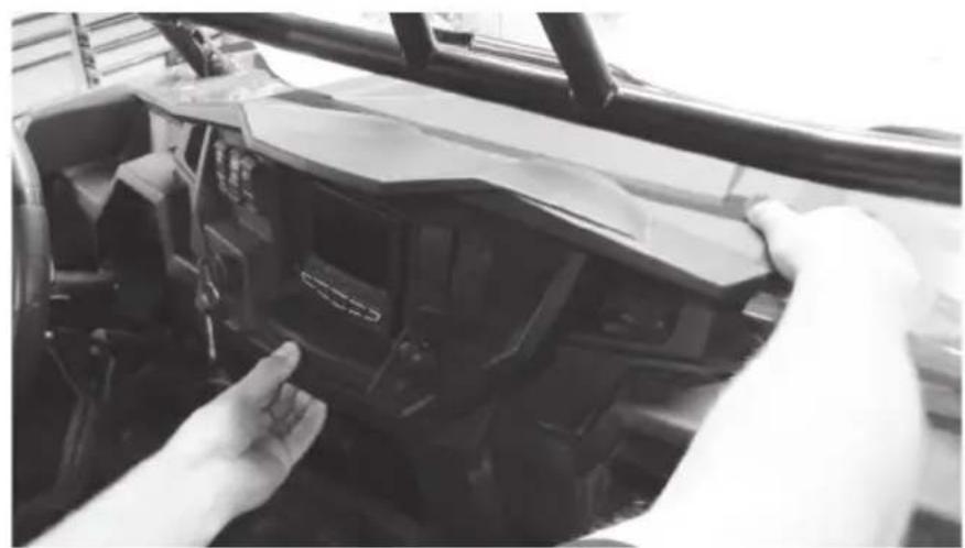
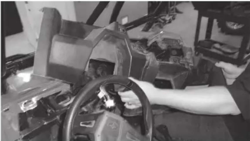
Step 9 - Carefully lift the dash out of the vehicle. There are locking clips on the right and left side that hold it in place. The dash will pop out. If the locking clips have fallen off, place them back onto the locking tabs on the dash. These are needed to re-assemble the dashboard.
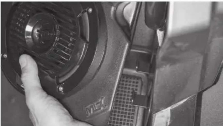
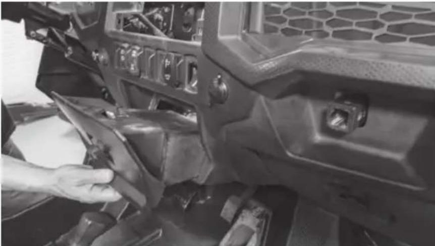
Step 10 - Remove the retaining clips holding the passenger side dash compartment in place. Remove the compartment.
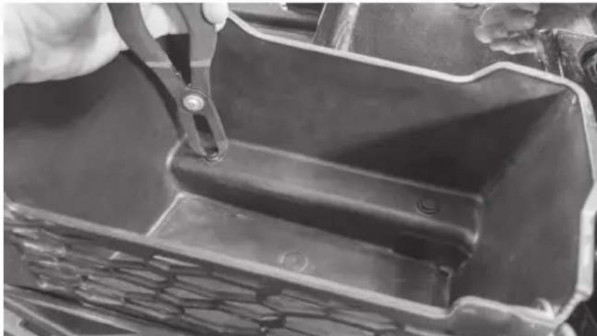
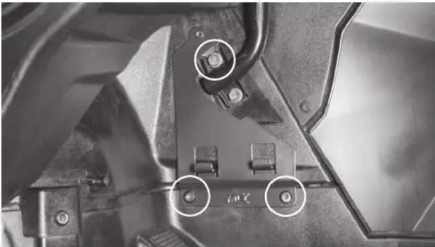
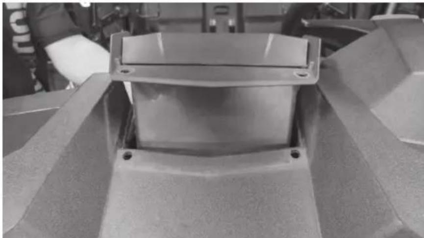
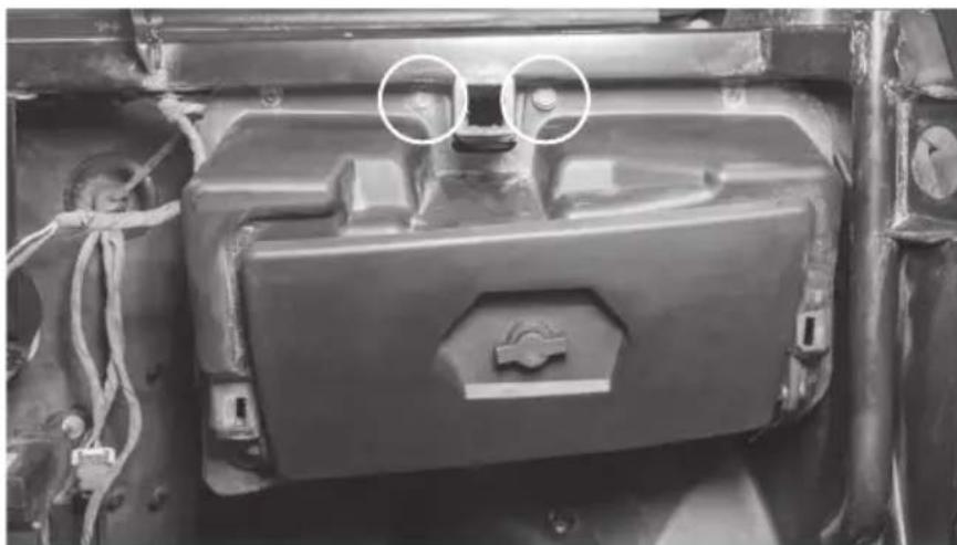
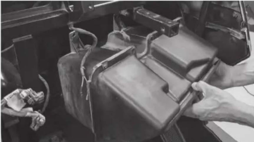
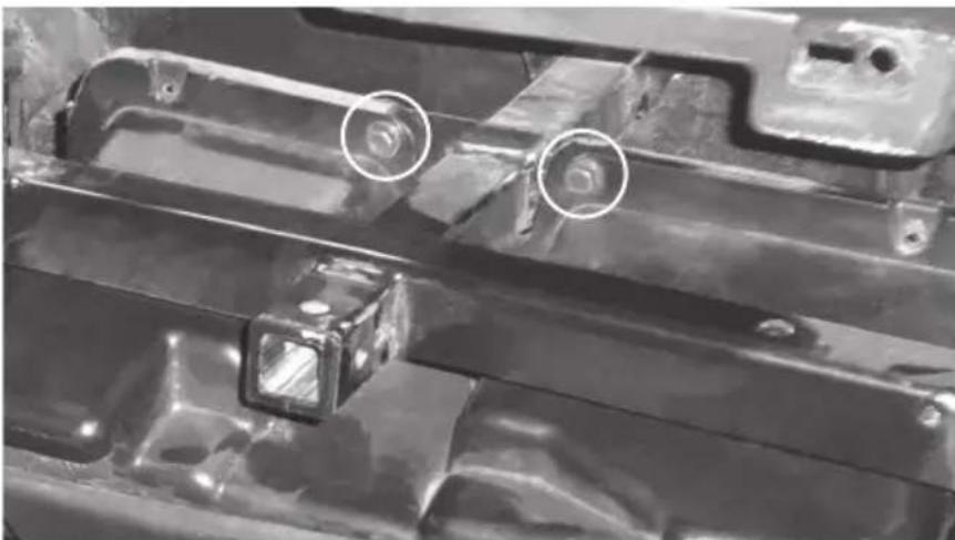
Step 11 - Remove the two (2) 10mm bolts above the glove box.
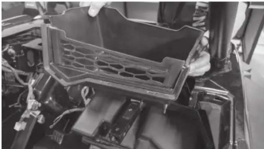
Step 12 - Remove the glove box.
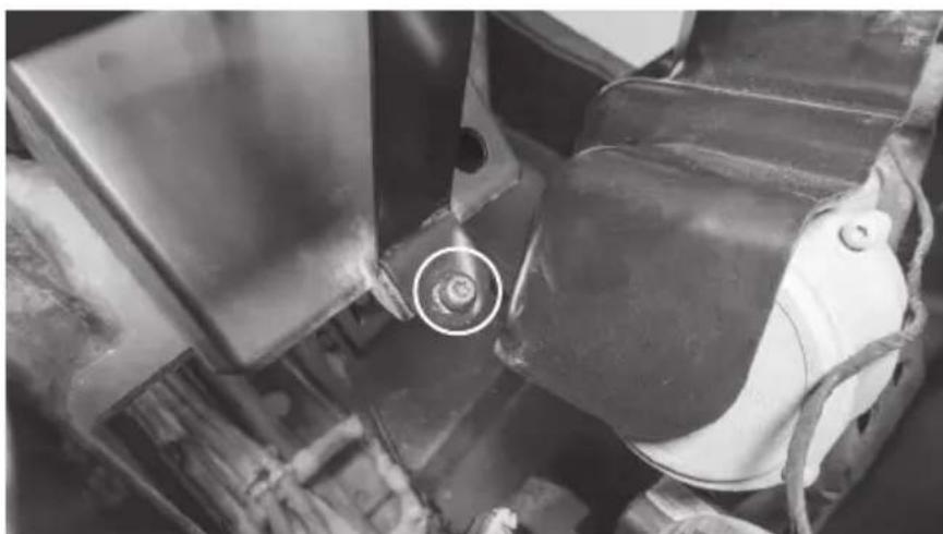
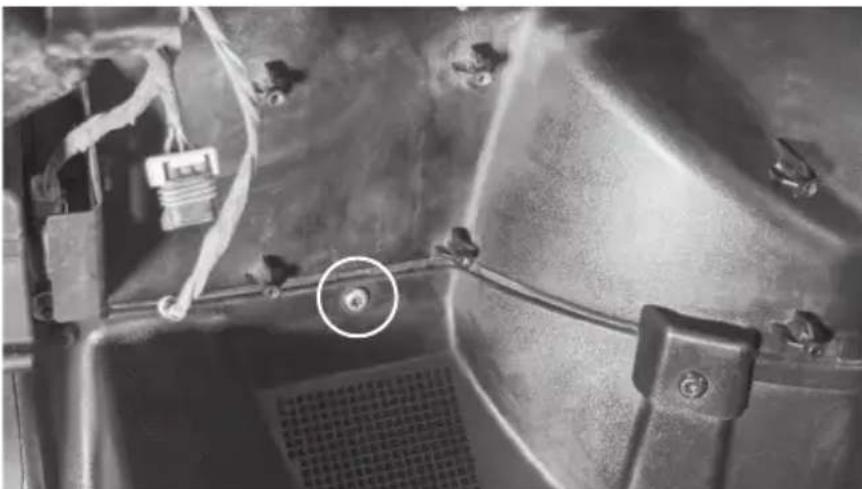
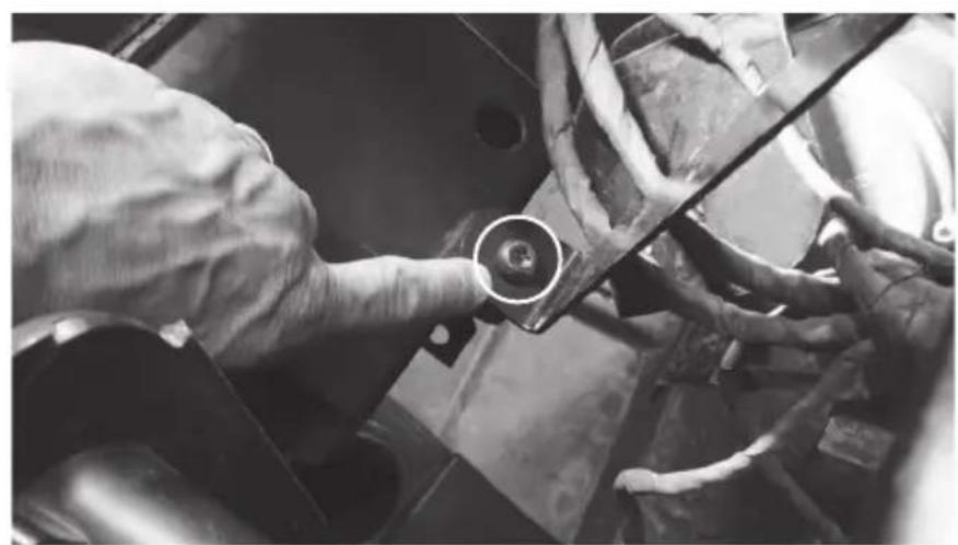
Step 13 - Remove one (1) T40 Torx screw located directly above left foot rest on passenger side.
The vehicle disassembly process is now complete. Please turn to page 14 to continue with the product installation process.
DISASSEMBLY - RZR MODELS 2014 - 2018
Step 1 - Release the two quick locks to remove the hood from the vehicle.
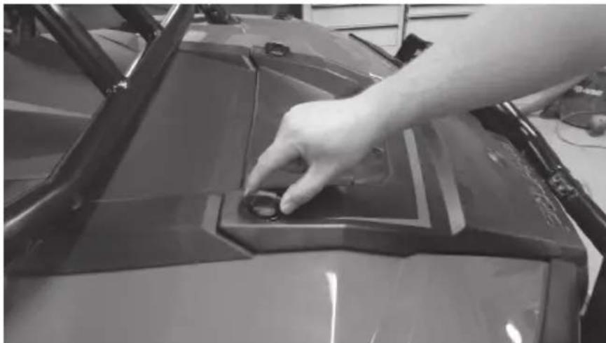
Step 2 - Lift up the hood and slide towards the front of the vehicle.
Step 3 - Remove the two (2) T40 screws holding down the top dash cover.
Step 4 - Lift and pull back the top dash cover to release the clips holding it in place. Unplug the gauge and switches making sure not to damage the vehicle and ignition wiring. Make note to remember what connector is associated with each specific switch.
Step 5 - Remove the Torx head screw from the dash pocket brace. After this is removed the plastic dash pocket and bracket can be pulled out of the dash.
Step 6 - Remove the two (2) T40 screws holding the dashboard in place.
Step 7 - Pull the dashboard towards the back of the vehicle. There are locking clips on the right and left side that hold it in place. The dash will pop out.
Step 8 - Carefully lift the dash out of the vehicle. If the locking clips have fallen off, place them back onto the locking tabs on the dash. These are needed to re-assemble the dashboard.
Step 9 - Remove the two (2) 10mm hex bolts that are holding the glove box to the vehicle frame. When the screws are removed the glove box can be lowered down and out of the enclosure.
The vehicle disassembly process is now complete. Please turn to page 14 to continue with the product installation process.
INSTALLATION
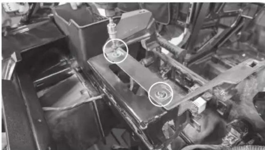
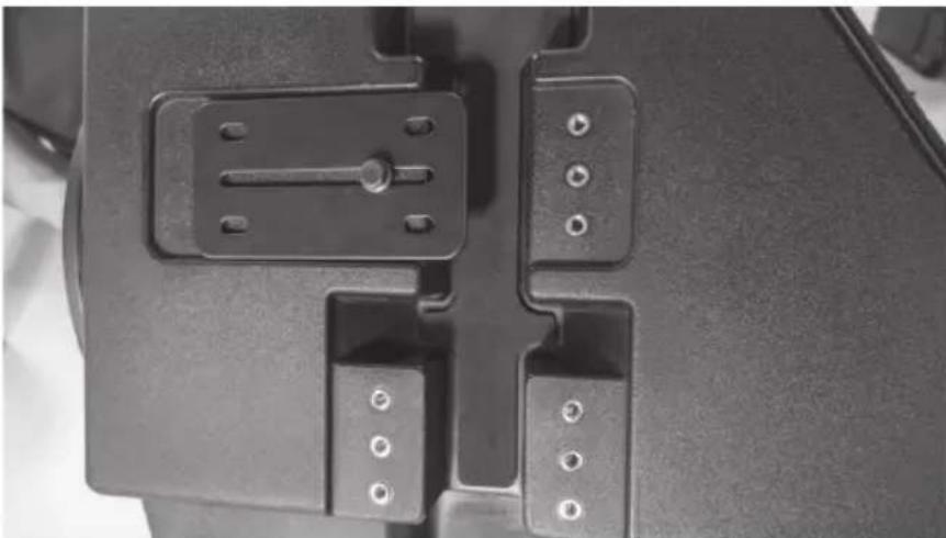
Step 1 - Install the large hardware bracket on the RZR-14-SW subwoofer enclosure using one 10mm bolt as pictured. Hand-tighten so the bracket is able to slide left to right.
Step 2 - Hang the subwoofer enclosure from the T-handle mounting bar as shown by sliding the installed bracket over the bar. Install five additional 10mm bolts hand-tight.
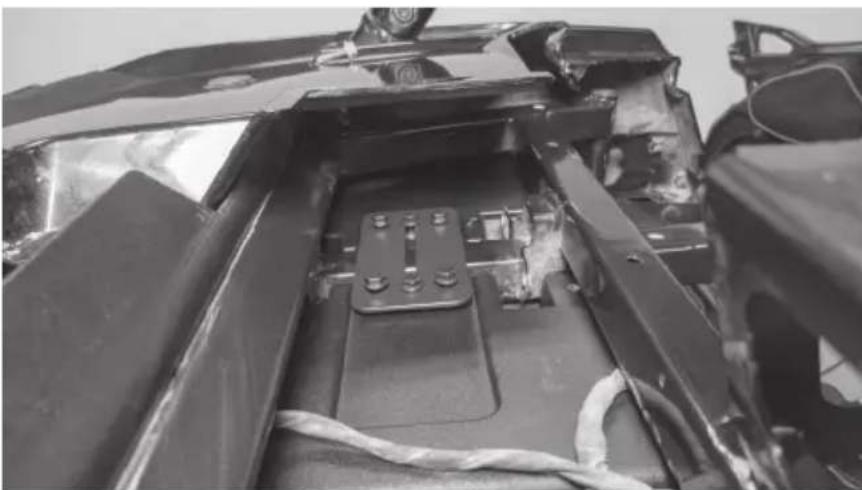
Note: The second mounting bracket included is used for all 2014 - 2018 models only.
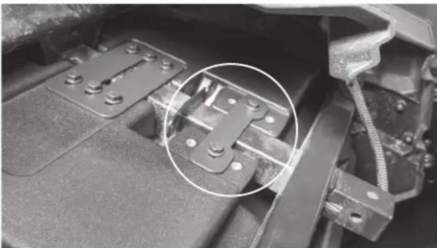
Step 3 - Install the supplied Torx screw in the lower mounting hole aligning with the factory hole in the footwell and tighten.
Step 4 - Tighten all remaining hardware.
Step 5 - Feed wire into dash towards amplifier mounting location. Note: In the event this is not used with an MTX THUNDER SYSTEM, it will be necessary to cut off the connector and hardwire directly to your equipment.
Step 6 - Reassemble and go ride.
WARRANTY PERIOD
At MTX Audio we engineer products that will stand up to the test of time. We also realize that from time to time a problem may occur. That's why our products carry a 2-year limited warranty that begins at the time of sale to the end user.
Of course, we're here to help. If you experience an issue with any of our products within the warranty period, please contact our customer service technical line at 1-800-CALL-MTX to help troubleshoot your issue. If, after speaking with our technical experts it is determined that a problem lies with the product, the technician will provide you with a Return Authorization number and all relevant details you'll need to get the product taken care of.
MITEK WARRANTY
Mitek Mobile products (including, but not limited to: MTX, Coustic, Streetwires, Xtant, BassSlammer, and Thunder Marine) purchased in the USA from an AUTHORIZED MITEK DEALER are guaranteed against defects in material and workmanship for the period of time specified. The warranty period begins the day the product is purchased by the end user, and this warranty is limited to the original retail purchaser of product. Products found to be defective during the warranty period will be repaired or replaced with equivalent product by Mitek at no charge. This warranty is void if it is determined that unauthorized parties have attempted repairs or alterations of any nature, and the warranty does not extend to cosmetics or finish. Mitek disclaims any liability for other incurred or consequential damages resulting from product defects. Mitek's total liability will not exceed the purchase price of the product.

Let's Get Social mtx.com

Like, Follow, & Subscribe
© 2020 Mitek Corporation. All rights reserved. MTX is a trademark of Mitek Corporation. All other trademarks are property of their respective owners. Designed and Engineered in the U.S.A.
Due to continual product development, all specifications are subject to change without notice.
MTX Audio, 4545 East Baseline Rd. Phoenix, AZ 85042 U.S.A. 1-800-225-5689
MTX006073 RevA 2/20 • 21A10765 • AW0015798
MUDLEDC
LED REMOTE CONTROL
OWNER'S MANUAL
PRODUCT INFORMATION
Model#
Serial #
Dealer's Name
Date of Purchase
IN THE BOX
Remote Control
RF Receiver
INTRODUCTION
Thank you for purchasing the MUDLEDC LED remote control. This remote expands the functionality of RGB LED equipped components like the MUD65PL. Up to 12 speakers can be connected to the MUDLEDC in parallel. For additional speakers, additional remotes will be required. Congratulations and enjoy the ultimate audio experience with MTX!
SPECIFICATIONS
Dynamic Modes: 19 Modes
Static Colors: 20 Colors
Brightness: 5 Levels
Speed: 10 Levels
Demo Mode: Yes
Working Voltage (V): +12
Output Current (A): 3-way, 4A peak per channel
Remote Frequency (MHz): 433.92
Remote Distance (M): 30 (open area)

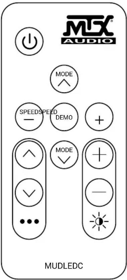
GENERAL OPERATION
- Power / Standby - Power on or switch to standby mode.
- Speed Down - Press to decrease speed of flash.
- Speed Up - Press to increase speed of flash.
- Static Color - Cycle through static colors.
- Static Color - Cycle through static colors.
- Adjust Dynamic Mode - Cycle through dynamic modes.
- Adjust Dynamic Mode - Cycle through dynamic modes.
- Brightness Up - Press to increase brightness.
- Brightness Down - Press to decrease brightness.
- Demo Mode - Loop through nine dynamic modes. Each mode will play three times.
INSTALLATION
Do not install the dongle/RF receiver in enclosed metal parts, as this may interfere with connectivity between it and the remote. Remote Battery: 3V CR2025 (use only the approved battery)
Connect the MUDLEDC LED pig-tail (left) to the MUDLEDC LED dongle (right). The dongle is keyed and will only fit when oriented properly. To prevent battery discharge, install a switch on the RED MUDLEDC power wire so you can turn off the MUDLEDC's remote receiver when the vehicle is stored.

- You can use the remote turn-on lead from the head unit to trigger a relay. However, do not connect the MUDLEDC power wire directly to the head unit power wire; it pulls more current than a typical turn-on circuit provides.
- You can also use the stereo's rocker-style power switch on the dash, if equipped, to turn the MUDLEDC controller On and Off.
- You can also simply install a toggle or rocker-switch in a convenient location.
Do not wire your MUDLEDC's power wire into your navigational lighting circuit. Depending on USCG or local laws, it may be inappropriate or illegal to be showing navigation lights and accent lighting.
Connect all LED capable speakers and MUDLEDC LED pig-tail wires together according to color. Each LED pig-tail will have Green, Red, Blue, and Black wires. Splice every green wire together, every red wire together et al. Test for functionality with the remote. Troubleshoot beginning with power and LED wiring. If problems persist, test with one speaker to ensure the MUDLEDC is functioning properly.
© 2018 Mitek Corporation. All rights reserved. MTX, Mud Nation, and Let's Do Something Dirty are trademarks of Mitek Corporation. All other trademarks are property of their respective owners. Designed and Engineered in the U.S.A.
Due to continual product development, all specifications are subject to change without notice.
MTX Audio, 4545 East Baseline Rd. Phoenix, AZ 85042 U.S.A. 1-800-225-5689
MTX005868 RevA 10/18 •21A10687 • AW0015693