RZR-14-SW - Speaker MTX Audio - Free user manual and instructions
Find the device manual for free RZR-14-SW MTX Audio in PDF.

| Product Type | Car Audio Subwoofer |
| Brand | MTX Audio |
| Model | RZR-14-SW |
| Speaker Size | 14 inches |
| Impedance | 4 ohms (single voice coil) |
| RMS Power Handling | 600 watts |
| Peak Power Handling | 1200 watts |
| Sensitivity | 88 dB (1W/1m) |
| Frequency Response | 22 Hz – 200 Hz |
| Mounting Depth | 7.5 inches |
| Cutout Diameter | 12.6 inches |
| Voice Coil Diameter | 2.5 inches |
| Woofer Cone Material | Injected polypropylene |
| Surround Material | Rubber |
| Magnet Weight | 120 oz |
| Recommended Enclosure | Sealed or ported |
| Weight | 28 lbs |
| Dimensions (Diameter x Depth) | 14.6 x 8.2 inches |
| Mounting Hardware | Included |
| Warranty | 1 year limited |
Frequently Asked Questions - RZR-14-SW MTX Audio
User questions about RZR-14-SW MTX Audio
0 question about this device. Answer the ones you know or ask your own.
Ask a new question about this device
Download the instructions for your Speaker in PDF format for free! Find your manual RZR-14-SW - MTX Audio and take your electronic device back in hand. On this page are published all the documents necessary for the use of your device. RZR-14-SW by MTX Audio.
USER MANUAL RZR-14-SW MTX Audio
text_image
MTK AUDIO POWERSPORTS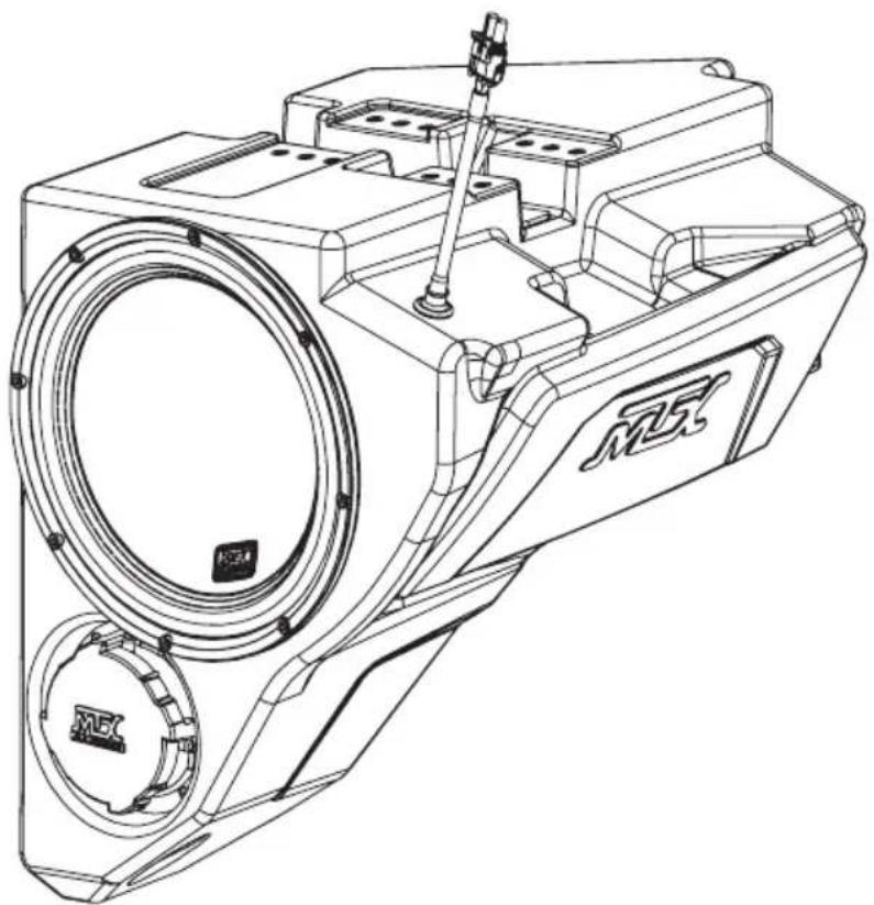
natural_image
Technical line drawing of a mechanical device with no visible text or symbolsRZR-14-SW
POLARIS® RZR® SUBWOOFER ENCLOSURE
OWNER'S MANUAL

THANK YOU
Congratulations and thank you for purchasing the MTX Audio direct-fit subwoofer enclosure designed for the Polaris® RZR®. Our sub enclosure, with its high output 10" subwoofer, will belt out the bass and deliver ground pounding audio making you the party vehicle in any ride! With a few basic hand tools in your trusty toolbox, you can have this installed in no time. So, what are you waiting for? It's time to get the rumble in your ride and go hit the trails! Oh, and congratulations on your purchase, thanks for your support and most importantly, enjoy the ultimate audio experience with MTX!
WE'RE HERE TO HELP
We're here to help with any installation or technical support. Visit mtx.com to chat, call 1-800-225-5689 to speak with an MTX Technical Support representative, or visit youtube.com/user/MTXAudioUSA to view product videos.
DON'T FORGET TO REGISTER YOUR PRODUCT
Don't forget to register your new MTX Audio product. Visit mtx.com/productregistration or scan the QR code to the right.
Model # ____
Serial # ____
Dealer's Name ____
Date of Purchase

MAKE SURE TO READ THIS
Installation of this enclosure will delete the factory supplied glove box.
If the RZR-14-SW subwoofer enclosure is being installed along with the RZR-14-FS kick panel speaker pods, the subwoofer must be installed first.
The Quick Install Port Seal cap allows the enclosure to be used as a sealed system. For maximum bass, we recommend removing the cap for normal operation but keeping it in the vehicle. In the event of a deep water or submersion situation, the cap can quickly be reinstalled to prevent water penetration into the enclosure.
IMPORTANT NOTICE
Whenever working on the vehicle, it is recommended to disconnect the battery prior to starting work. Failure to do so may lead to a risk of electric shock or equipment damage.
When connecting power and ground wires ensure that the red power wire is fused at the point where it is connected to the vehicle's battery. Failure to do so can result in damage to the vehicle if a short circuit develops between the vehicle connection point and the product.

FEATURES
- Can Be Used as a Ported or Sealed Enclosure
- Includes an MTX 55 Series Subwoofer for its Deep Bass Reproduction Capabilities
• QuIPS (Quick Install Port Seal) Technology - Mounts Behind Dashboard
• Factory Matched Texture
• Installer Friendly Design - Direct Fit, No Cutting or Drilling Required
SPECIFICATIONS
• 10" Loaded Subwoofer Enclosure
• RMS Power Handling: 400-Watts
• Peak Power Handling: 800-Watts
• Sensitivity (2.83V/1m): 90.2dB
• Sensitivity (1W/1m): 83.5dB
• Frequency Response: 28Hz - 130Hz
- Impedance: Dual 4
FIT GUIDE
RZR 900....2014 - 2020
RZR 900 XC 2015 - 2020
RZR 2 900 EPS....2014 - 2018
RZR 4 900 EPS....2014 - 2020
RZR S 900....2014 - 2020
RZR S 1000....2017 - 2020
RZR S4 1000....2019 - 2020
RZR XP 1000....2014 - 2020
RZR XP Turbo 2016 - 2020
RZR XP Turbo S....2019 - 2020
RZR XP Turbo Dynamix Edition 2018 - 2020
RZR XP 4 1000....2014 - 2020
RZR XP 4 Turbo 2016 - 2020
RZR XP 4 Turbo S....2019 - 2020
RZR XP 4 Turbo Dynamix Edition....2018 - 2020
RZR XP 1000 Trails and Rocks....2019 - 2020
RZR XP 1000 High Lifter....2014 - 2020
RZR XP 4 1000 High Lifter....2014 - 2020
FIT GUIDE NOTES
Kits featuring a subwoofer are not compatible with Polaris® heater option (located where the subwoofer enclosure should fit).
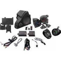
IN THE BOX
• RZR-14-SW Loaded Subwoofer Enclosure
- Mounting Hardware
(2) Mounting Brackets
(6) 10mm Screws
(1) T40 Torx Screw
DISASSEMBLY - RZR MODELS 2019+
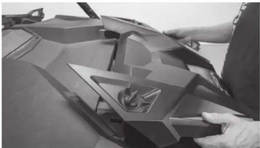
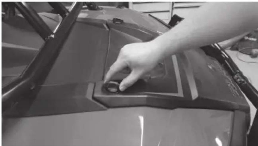
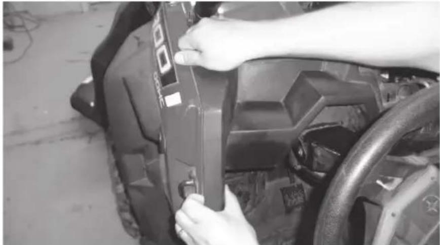
Step 1 - Release the two quick locks to remove the hood from the vehicle. Lift the hood and slide it towards the front of the vehicle
natural_image
Person adjusting a 3D-printed car body panel, no visible text or symbolsStep 2 - Remove the four (4) T40 screws holding down the top dash cover.
natural_image
Close-up of a mechanical assembly with visible components and a hand adjusting parts (no text or symbols)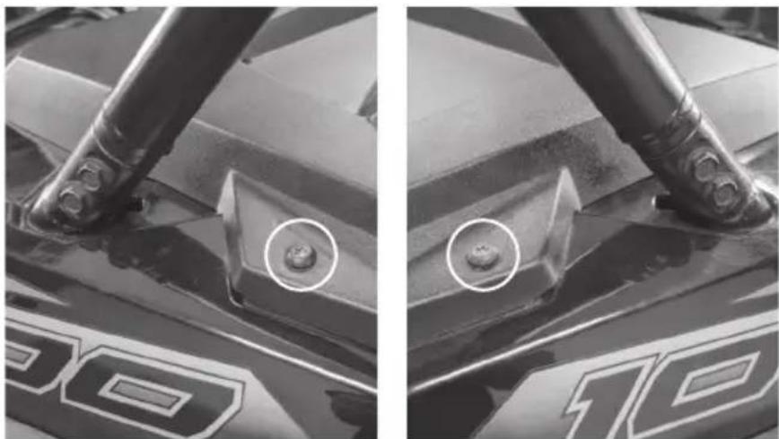
natural_image
Close-up of a mechanical component with two views showing a bolt and a bracket (no text or symbols visible)Driver Side Passenger Side
Step 3 - Remove the retaining clips holding the center dash compartment in place. Remove the compartment.
natural_image
Close-up of a person using a 3D printer to press or install a mechanical component on a flat surface (no visible text or symbols)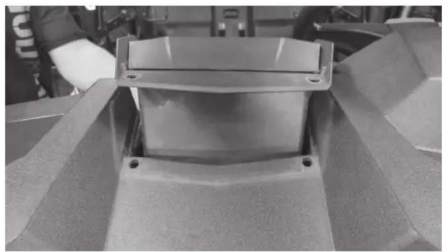
natural_image
Close-up of a mechanical component with a rectangular housing and mounting holes (no visible text or symbols)Step 4 - Remove the dash top panel.
natural_image
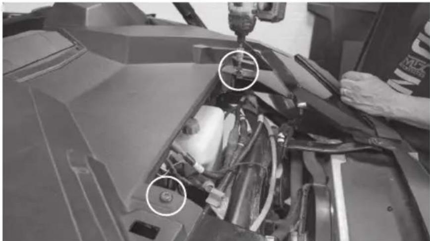
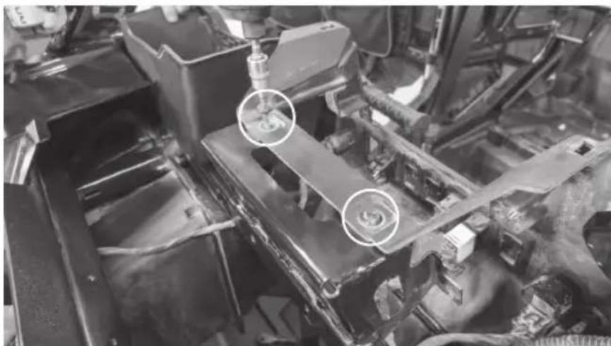
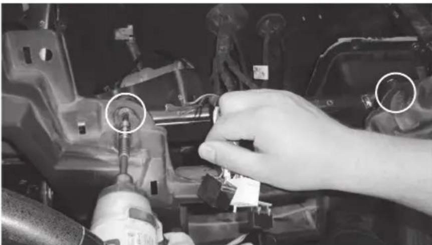
Person installing or adjusting a vehicle chassis frame, no visible text or symbolsStep 5 - Remove the two (2) bolts in the center behind the dash. Note: For vehicles with Ride Command units, you may find two additional bolts on either side of the display. Remove these if present.
natural_image
Close-up of an automotive chassis frame with two circular annotations highlighting specific components (no readable text or symbols)Step 6 - Remove the T-handle and clip.
natural_image
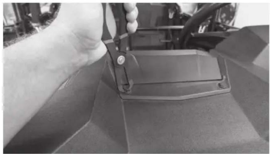
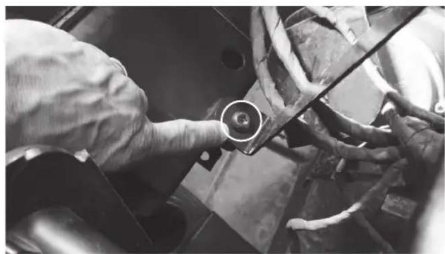
Close-up of a vehicle's internal components, possibly engine or chassis, showing no visible text or symbols.Step 7 - Remove the Torx head screw from the dash pocket brace. After this is removed the plastic dash pocket can be pulled out of the dash.
natural_image
Close-up of mechanical components with a circular annotation highlighting a bolt detail (no visible text or symbols)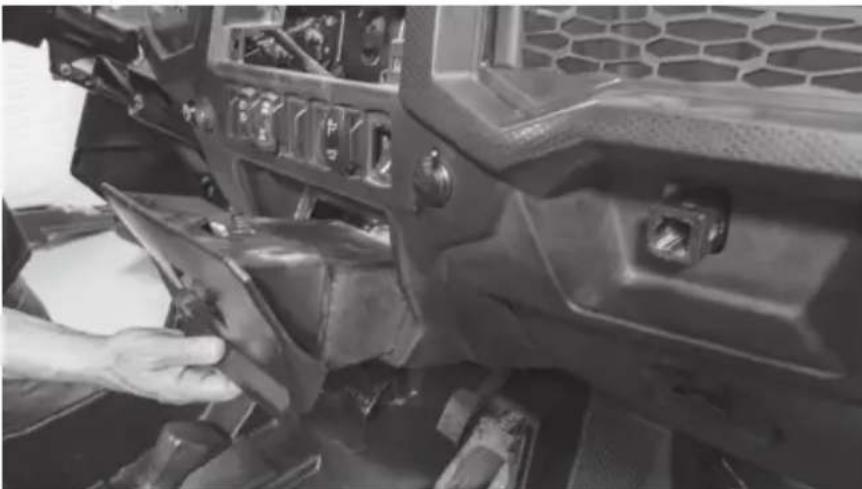
natural_image
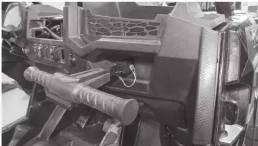
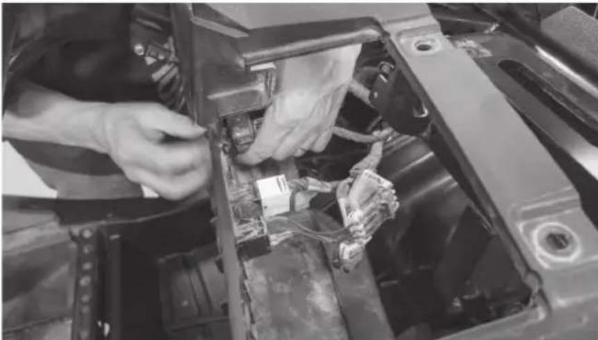
Close-up of a hand adjusting a vehicle's seat frame with a tool, no visible text or symbolsStep 8 - Unplug the gauge and switches making sure not to damage the vehicle and ignition wiring. Make note to remember what connector is associated with each specific switch.
natural_image
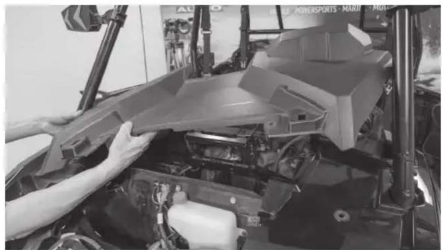
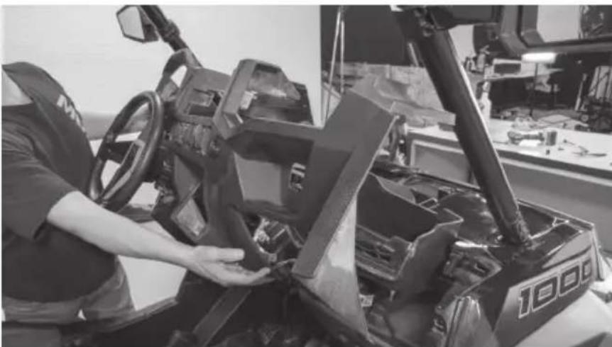
Close-up of hands installing or adjusting a car engine compartment with visible wiring and components (no text or symbols)Step 9 - Carefully lift the dash out of the vehicle. There are locking clips on the right and left side that hold it in place. The dash will pop out. If the locking clips have fallen off, place them back onto the locking tabs on the dash. These are needed to re-assemble the dashboard.
natural_image
Interior view of a tractor cockpit with a worker adjusting the frame (no visible text or symbols)Step 10 - Remove the retaining clips holding the passenger side dash compartment in place. Remove the compartment.
natural_image
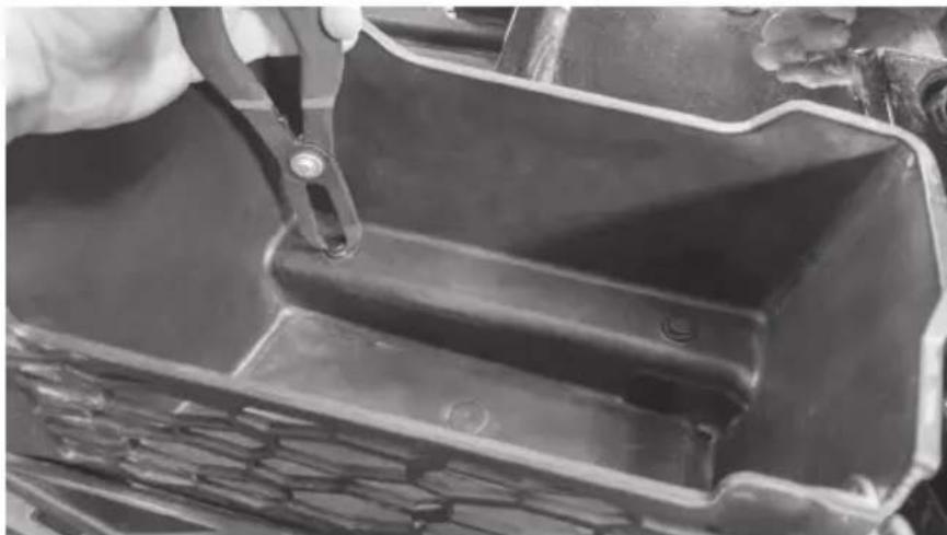
Close-up of a hand using a tool to cut or inspect the internal structure of a black metal frame (no visible text or symbols)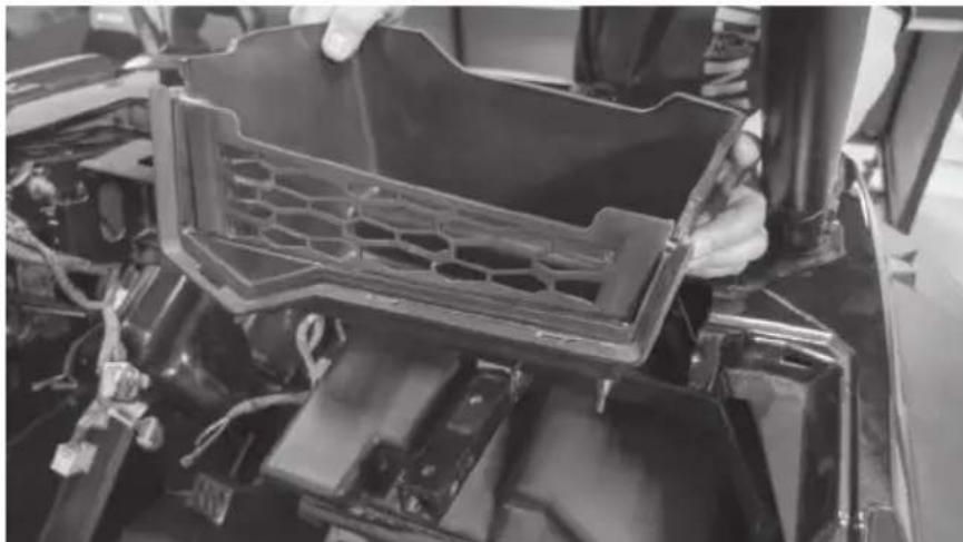
natural_image
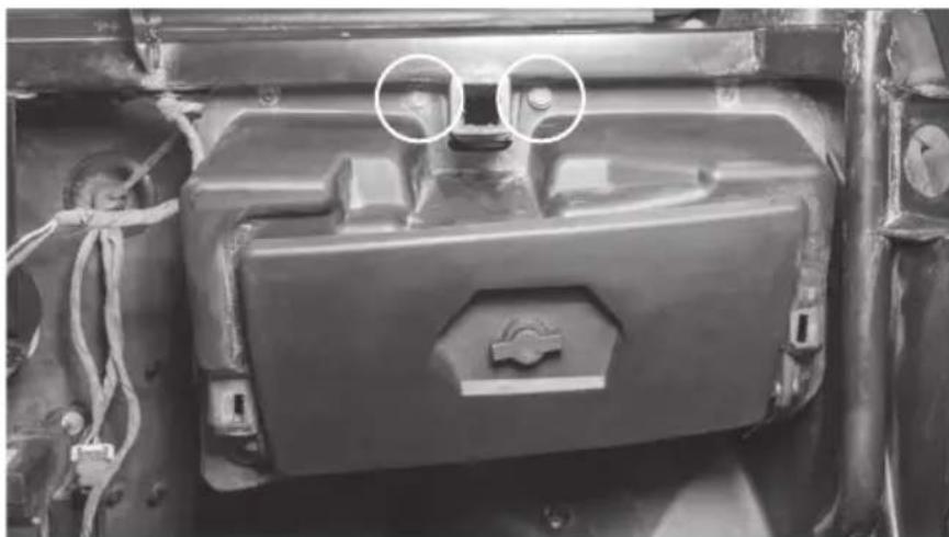
Close-up of hands installing a black plastic panel on a vehicle chassis (no visible text or symbols)Step 11 - Remove the two (2) 10mm bolts above the glove box.
natural_image
Close-up of a mechanical component with two circled features, no visible text or symbolsStep 12 - Remove the glove box.
natural_image
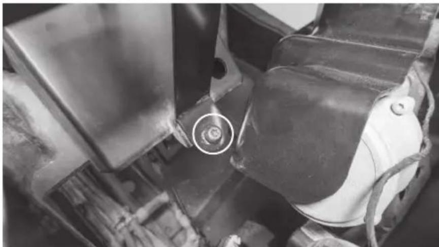
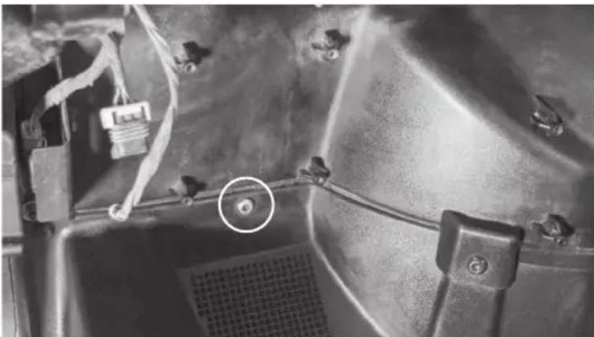
Close-up of hands cleaning or inspecting a car body panel with visible mechanical components (no text or symbols)Step 13 - Remove one (1) T40 Torx screw located directly above left foot rest on passenger side.
natural_image
Close-up of a mechanical component with wires and a highlighted circular feature (no visible text or symbols)The vehicle disassembly process is now complete. Please turn to page 14 to continue with the product installation process.
DISASSEMBLY - RZR MODELS 2014 - 2018
Step 1 - Release the two quick locks to remove the hood from the vehicle.
natural_image
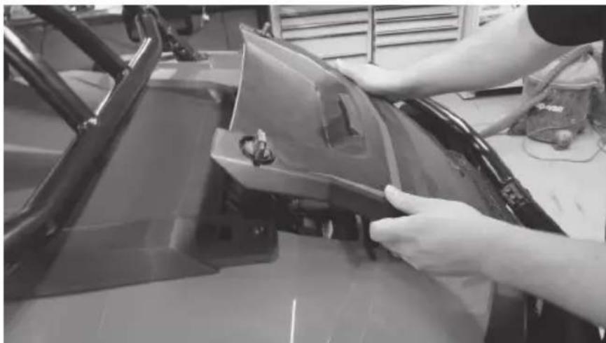
Close-up of a hand pressing down on a car's front panel (no visible text or symbols)Step 2 - Lift up the hood and slide towards the front of the vehicle.
natural_image
Person working on a car body panel with tools, no visible text or symbolsStep 3 - Remove the two (2) T40 screws holding down the top dash cover.
natural_image
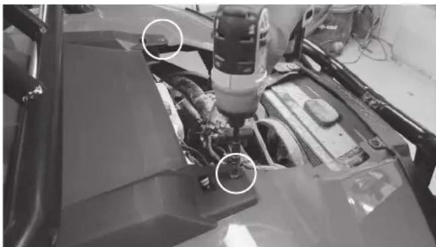
Close-up of a car engine bay with a drill bit and two circled mechanical components (no visible text or symbols)Step 4 - Lift and pull back the top dash cover to release the clips holding it in place. Unplug the gauge and switches making sure not to damage the vehicle and ignition wiring. Make note to remember what connector is associated with each specific switch.
natural_image
Person cleaning a car interior panel with visible dashboard and door (no text or symbols)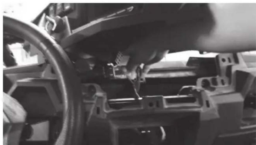
natural_image
Close-up of a car's dashboard and steering wheel assembly (no visible text or symbols)Step 5 - Remove the Torx head screw from the dash pocket brace. After this is removed the plastic dash pocket and bracket can be pulled out of the dash.
natural_image
Close-up of a worker's hand holding a mechanical component with a circular detail (no visible text or symbols)Step 6 - Remove the two (2) T40 screws holding the dashboard in place.
natural_image
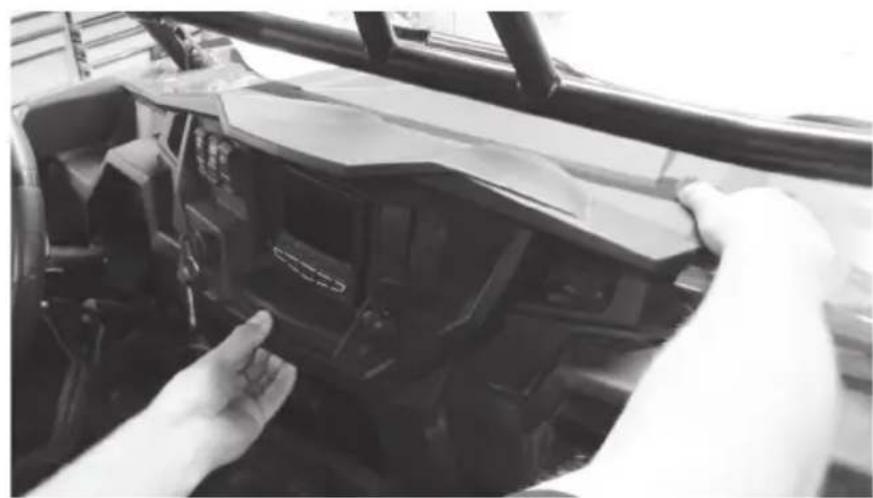
Close-up of a hand adjusting automotive components with a tool, no visible text or symbolsStep 7 - Pull the dashboard towards the back of the vehicle. There are locking clips on the right and left side that hold it in place. The dash will pop out.
natural_image
Close-up of hands installing or adjusting a mechanical component on a vehicle (no visible text or symbols)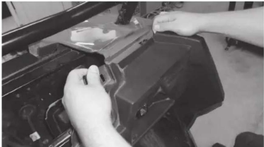
natural_image
Close-up of hands installing or adjusting a black plastic component on a vehicle chassis (no visible text or symbols)Step 8 - Carefully lift the dash out of the vehicle. If the locking clips have fallen off, place them back onto the locking tabs on the dash. These are needed to re-assemble the dashboard.
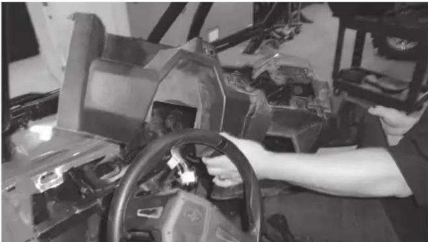
natural_image
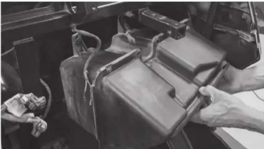
Black-and-white photo of a person working on an automotive steering wheel and dashboard in a workshop (no visible text or symbols)Step 9 - Remove the two (2) 10mm hex bolts that are holding the glove box to the vehicle frame. When the screws are removed the glove box can be lowered down and out of the enclosure.
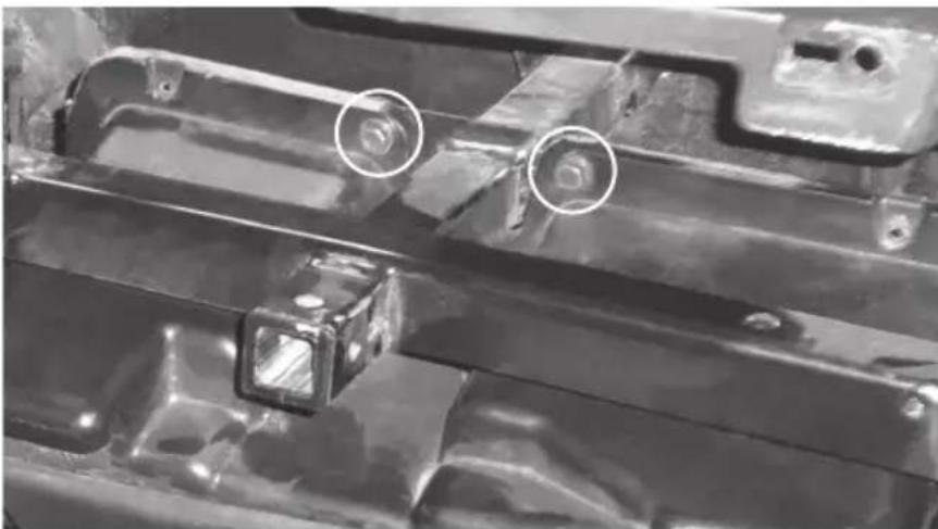
natural_image
Close-up of a metal automotive component with two circular annotations highlighting features (no readable text or symbols)The vehicle disassembly process is now complete. Please turn to page 14 to continue with the product installation process.
INSTALLATION
Step 1 - Install the large hardware bracket on the RZR-14-SW subwoofer enclosure using one 10mm bolt as pictured. Hand-tighten so the bracket is able to slide left to right.
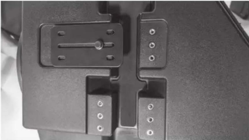
natural_image
Close-up of a mechanical component with multiple slots and mounting holes (no visible text or symbols)Step 2 - Hang the subwoofer enclosure from the T-handle mounting bar as shown by sliding the installed bracket over the bar. Install five additional 10mm bolts hand-tight.
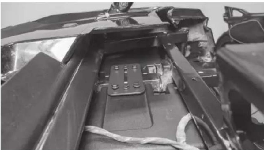
natural_image
Close-up of a car's front panel showing internal components and wiring (no visible text or symbols)Note: The second mounting bracket included is used for all 2014 - 2018 models only.
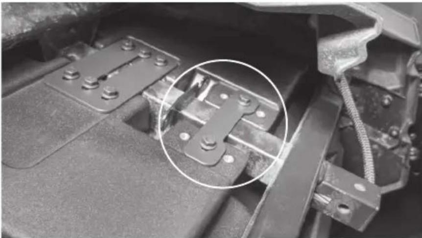
natural_image
Close-up of a mechanical assembly with metal brackets and bolts, circled in white (no text or symbols visible)Step 3 - Install the supplied Torx screw in the lower mounting hole aligning with the factory hole in the footwell and tighten.

natural_image
Close-up of a hand using a tool to adjust or install a component, no visible text or symbolsStep 4 - Tighten all remaining hardware.
Step 5 - Feed wire into dash towards amplifier mounting location. Note: In the event this is not used with an MTX THUNDER SYSTEM, it will be necessary to cut off the connector and hardwire directly to your equipment.
Step 6 - Reassemble and go ride.
WARRANTY PERIOD
At MTX Audio we engineer products that will stand up to the test of time. We also realize that from time to time a problem may occur. That's why our products carry a 2-year limited warranty that begins at the time of sale to the end user.
Of course, we're here to help. If you experience an issue with any of our products within the warranty period, please contact our customer service technical line at 1-800-CALL-MTX to help troubleshoot your issue. If, after speaking with our technical experts it is determined that a problem lies with the product, the technician will provide you with a Return Authorization number and all relevant details you'll need to get the product taken care of.
MITEK WARRANTY
Mitek Mobile products (including, but not limited to: MTX, Coustic, Streetwires, Xtant, BassSlammer, and Thunder Marine) purchased in the USA from an AUTHORIZED MITEK DEALER are guaranteed against defects in material and workmanship for the period of time specified. The warranty period begins the day the product is purchased by the end user, and this warranty is limited to the original retail purchaser of product. Products found to be defective during the warranty period will be repaired or replaced with equivalent product by Mitek at no charge. This warranty is void if it is determined that unauthorized parties have attempted repairs or alterations of any nature, and the warranty does not extend to cosmetics or finish. Mitek disclaims any liability for other incurred or consequential damages resulting from product defects. Mitek's total liability will not exceed the purchase price of the product.

text_image
MX AUDIO POWERSPORTSLet's Get Social
mtx.com

natural_image
Four black square icons representing social media platforms: Instagram, Twitter, Facebook, and YouTube (no text or symbols beyond logos)Like, Follow, & Subscribe
© 2020 Mitek Corporation. All rights reserved. MTX is a trademark of Mitek Corporation. All other trademarks are property of their respective owners. Designed and Engineered in the U.S.A.
Due to continual product development, all specifications are subject to change without notice.
MTX Audio, 4545 East Baseline Rd. Phoenix, AZ 85042 U.S.A. 1-800-225-5689
MTX006073 RevA 2/20 • 21A10765 • AW0015798