
XECI - Receiver LD Systems - Free user manual and instructions
Find the device manual for free XECI LD Systems in PDF.
| Product type | Extension module for Ethernet control |
| Brand | LD Systems |
| Model | XECI |
| Compatibility | LD IPA series installation power amplifiers |
| Dimensions (W × H × D) | 82.5 × 36.5 × 76.3 mm |
| Weight | 50 g |
| Power consumption | 1.075 W (link disabled), 1.375 W (link enabled) |
| Connectivity | Ethernet RJ45 10/100 Base-T |
| Transmission protocol | TCP/IP and UDP |
| Chip | STM32H743 |
| LED indicators | LED Status (white/red) and RJ45 LED (Link/Activity) |
| IP reset function | IP Reset button (long press 5 seconds) |
| Control software | QUESTRA® (free download at www.ld-systems.com) |
| Supported operating systems | iOS, Android, Windows, macOS (for Questra Remote application) |
| Box contents | 1x XECI module, mounting instructions |
| Mounting | Installation in a dedicated slot of the IPA amplifier (screws included) |
| Safety | Installation by qualified personnel only; disconnect the amplifier before mounting; keep out of reach of children (small parts) |
| Maintenance and cleaning | Clean with a soft, dry cloth. Do not use aggressive cleaning agents. |
| Required network conditions | Multicast traffic enabled (IGMP); default static IP address 192.168.0.192/24 |
| Recycling | Product subject to WEEE directive; do not dispose with household waste |
| Warranty | See terms on manufacturer's website |
Frequently Asked Questions - XECI LD Systems
User questions about XECI LD Systems
0 question about this device. Answer the ones you know or ask your own.
Ask a new question about this device
Download the instructions for your Receiver in PDF format for free! Find your manual XECI - LD Systems and take your electronic device back in hand. On this page are published all the documents necessary for the use of your device. XECI by LD Systems.
USER MANUAL XECI LD Systems
natural_image
Red electronic circuit board with network ports and an Ethernet logo (no readable text beyond labels)XECI
ETHERNET CONTROL INTERFACE CARD FOR IPA SERIES LDXECI
CONTENTS / INHALTSVERZEICHNIS / CONTENU / CONTENIDO / TREŚĆ / CONTENUTO
ENGLISH
INFORMATION ON THIS QUICK GUIDE 4
PRODUCT INFORMATION 4
SAFETY INSTRUCTIONS 4
SCOPE OF DELIVERY 5
ASSEMBLY 5
CONNECTIONS, CONTROLS AND INDICATORS 6
NETWORK CONNECTION 6
TECHNICAL DATA 9
DISPOSAL 10
MANUFACTURER'S DECLARATIONS 11
DEUTSCH
PRODUKTINFORMATIONEN 12
INFORMATIONS SUR LE PRODUIT 20
CONSIGNES DE SÉCURITÉ 20
CONTENU DU CARTON 21
ASSEMBLY 21
CONNECTIONS, CONTROLS AND INDICATORS 22
CONNEXION RÉSEAU 22
CARACTÉRISTIQUES TECHNIQUES 25
MISE EN DÉCHETTERIE 26
DÉCLARATIONS DU FABRICANT 27
ESPAÑOL
Expansion module with Ethernet control interface for LD IPA installation power amplifiers.
INTENDED USE
This item is a product-specific accessory that is only intended for use with the LD Systems IPA installation power amplifier. These assembly instructions do not replace the operating instructions for the associated product. Always read the relevant operating instructions first. This accessory does not affect the intended use of the associated product. Observe the safety instructions in the operating instructions for the associated product! The technical data shown in the operating instructions can change in connection with this accessory item.
SAFETY INSTRUCTIONS
- Please read these instructions carefully.
- Keep all information and instructions in a safe place.
- Follow the instructions.
- Only use the accessories in the manner intended.

CAUTION: The installation of the expansion module may only be carried out by qualified personnel. If you are not qualified to do so, do not attempt to install the extension module yourself, but use the help of professional companies! Make sure that no foreign bodies get into the housing!
DANGER: KEEP AWAY FROM CHILDREN! THE PRODUCT CONTAINS SMALL PARTS THAT CAN BE SWALLOWED AND PACKAGING MATERIAL THAT CAN BE SWALLOWED! PLASTIC BAGS MUST BE KEPT OUT OF REACH OF CHILDREN!
SCOPE OF DELIVERY
Remove the product from the packaging and remove all packaging material. Please check that the delivery is complete and intact and please notify your distributor immediately after purchase if the delivery is not complete or damaged. The scope of delivery of the product includes:
- 1x XECI extension module
- Assembly instructions
ASSEMBLY
- Disconnect the power amplifier completely from the mains (pull out the mains plug)!
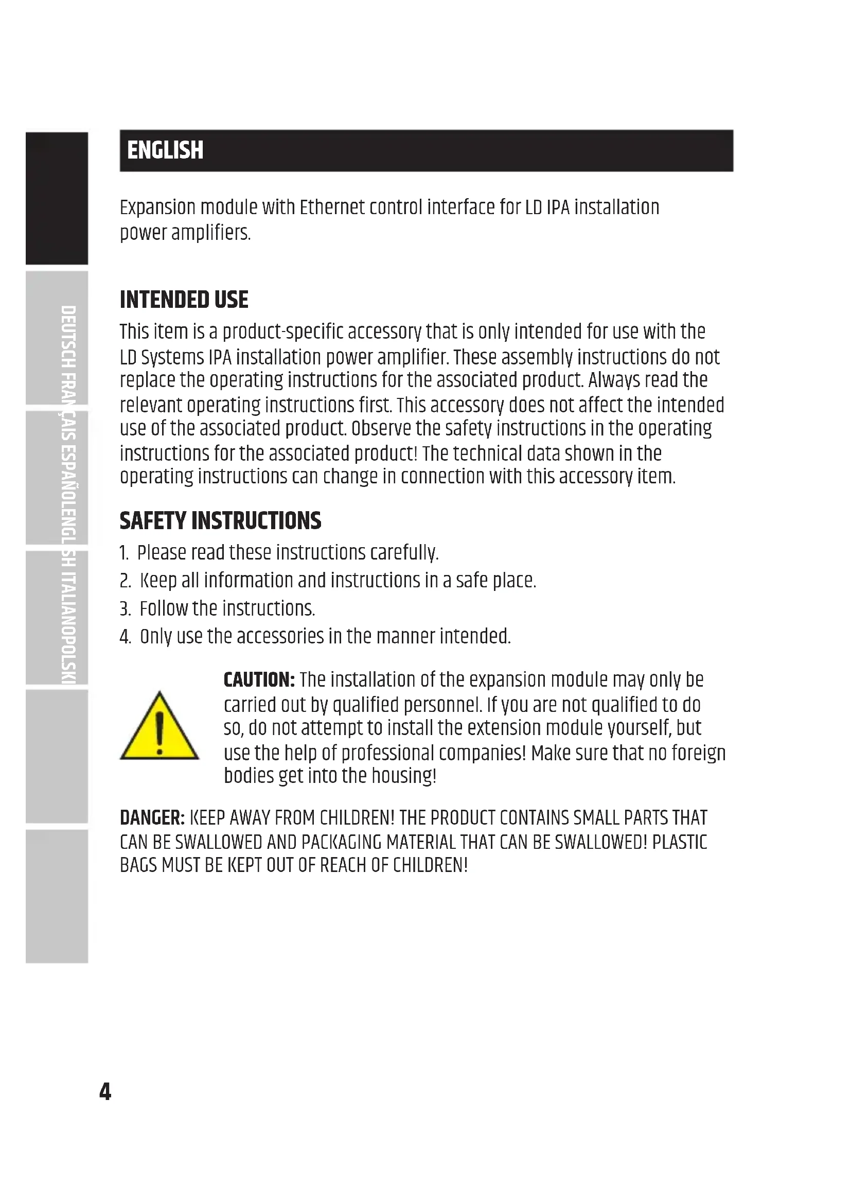
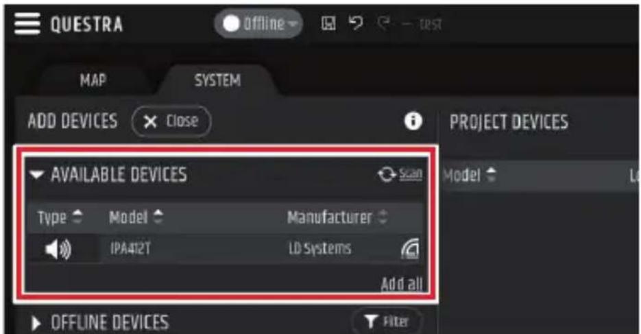
- Loosen and remove the four screws from the cover of the expansion slot using a suitable tool (see markings in the illustration). Keep the cover for later conversion.
- Slide the expansion module into the expansion slot, making sure that the contact strip of the module slides correctly into the connection strip of the power amplifier. Asymmetrically mounted guide pins on the module's plate ensure that the module cannot be installed the wrong way round A.
- Now screw the module to the power amplifier housing using the screws previously loosened from the expansion slot cover.
natural_image
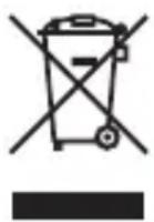
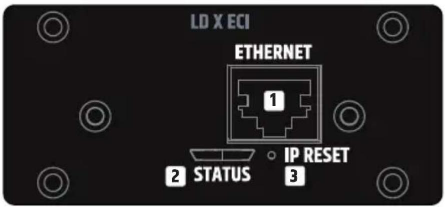
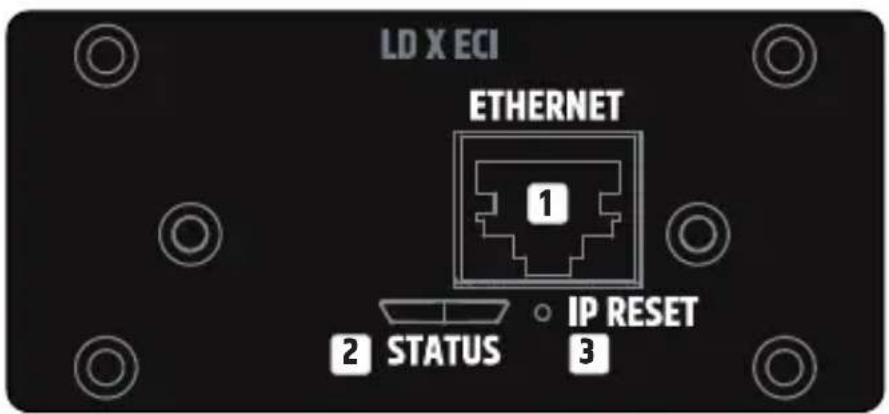
Close-up of a device rear panel with labeled ports and a close-up of its internal circuit board (no text or symbols visible)CONNECTIONS, CONTROLS AND INDICATORS

1 ETHERNET
Ethernet interface for controlling the installation amplifier via the free QUESTRA software.
2 STATUS
The status LED provides information about the internal integration between the card and the main board in the IPA power amplifier (firmware compatibility, internal communication problems):
- White flashing during start-up. The unit is loading the data for IPA.
- Permanently white: The network stack in the card is ready – The IP settings have been configured properly.
- Permanent red – Firmware is not compatible with motherboard, problems with network stack.
- White flashing (slow/fast) during IP reset procedure.
3 IP RESET
Long press activates the IP reset procedure. Initially, the status LED flashes slowly in white and when the button is pressed for 5 seconds, the status LED flashes quickly to indicate that the IP reset procedure will be carried out after the button is released.
NETWORK CONNECTION
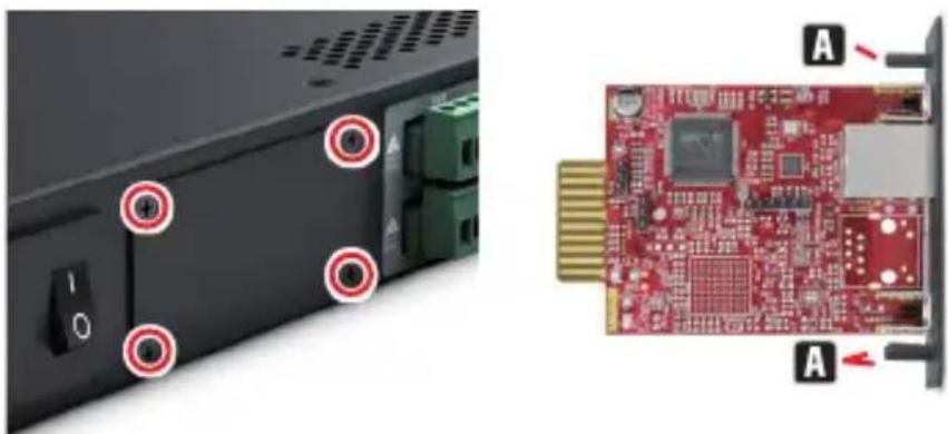
LD Systems' XECI module enables remote control of compatible devices, such as IPA series amplifiers, over the network. Once the XECI module is built into a device, it can be connected to a network infrastructure and controlled via a computer running LD Systems QUESTRA software.
PREREQUISITES FOR OPERATION
• Computer with QUESTRA software installed
- Network interface (router, switch) with activated multicast traffic (activate IGMP protocol).
- Ethernet cable. Use a standard RJ45 Ethernet cable (Cat 5e or better) for all wired connections.
FIRST STEPS
The XECI modules are delivered with a pre-configured static IP address (192.168.0.192) as standard. To be able to recognise the unit with the Questra software, please make sure that the IP settings of the computer on which the Questra software is installed are configured in the same network range as the XECI modules. See notes below.
- IP range : 192.168.0.X/24 (where X can be any value between 1 and 254, except 192 which is already used by default by the XECI modules)
• Network mask : 255.255.255.0
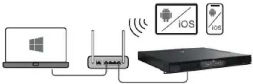
Once a device with a XECI module is connected to a network and switched on, it will appear under the AVAILABLE DEVICES section in the ADD DEVICES field on the left. Please note that multicast traffic must be enabled in the switch/router for the device to be detected.
Drag and drop the device into the PROJECT DEVICES area to be able to configure it. Then click the Offline button at the top of the screen and select Download from Devices and connect to connect to the device.
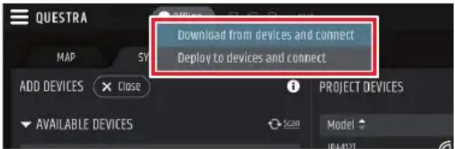
Once the unit is online, click on the unit in the PROJECT DEVICES list and select the SETTINGS menu on the right to go directly to the settings menu and change the IP settings of the unit. For more details about the complete unit configuration with the QUESTRA software, please download the latest version from the LD Systems website (www.ld-systems.com) to your computer and read the user manual.
QUESTRA SOFTWARE
The Questra software not only enables comprehensive configuration of compatible devices, such as IPA Series amplifiers, but also provides integration capabilities for third-party remote control units and allows users to create their own custom control panels that can be controlled via the Questra remote control apps available for iOS, Android, Windows and MAC OS.
Please download the latest version of the QUESTRA software from the LD Systems website (www.ld-systems.com) to your computer, check the system requirements for the software and follow the software instructions to start configuring a unit.
TECHNICAL DATA
Article number LDXECI
| Product type Expansion Card to add Ethernet control |
| Compatibility LD IPA installation power amplifiers |
| Control element Button for IP reset |
| Application software QUESTRA (free download) |
| Display elements RJ45 LEDs: Link / Activity2-colour LED for internal connection status |
| Dimensions (W × H × D) 82.5 × 36.5 × 76.3 mm |
| Weight 50 g |
Ethernet
| Interface RJ45 |
| Chip STM32H743 |
| Transmission protocol TCP/IP & UDP |
| Ethernet Standard 10/100 Base-T |
| Parallel connections 4 |
| Power consumption 1,075 W (Link Down), 1,375 W (Link Up) |
Indications
| Rear Panel | RJ45 LEDs: Link / ActivityStatus LED: internal connection status |
Software Application
| QUESTRA® (free download) |
DISPOSAL

PACKAGING :
- Packaging can be disposed of via the usual waste disposal channels.
- Please separate the packaging according to the waste disposal and materials regulations in your country.
DEVICE :
- This device is subject to the European Directive on Waste Electrical and Electronic Equipment in its applicable version. WEEE Directive-Waste Electrical and Electronic Equipment. Old devices and batteries do not belong in household waste. The old device or batteries must be disposed of via an approved waste disposal service or a municipal waste disposal facility. Follow the directives in your country!
- Follow the disposal laws in your country.
- As a private customer, you can obtain information on environmentally friendly disposal options from the retailer from whom you purchased the product or from the relevant regional authorities.
MANUFACTURER'S DECLARATIONS
MANUFACTURER'S WARRANTY & LIMITATION OF LIABILITY
Adam Hall GmbH, Adam-Hall-Str. 1, 61267 Neu Anspach, Germany
E-mail Info@adamhall.com / +49 (0)6081 / 9419-0.
Our current warranty conditions and limitation of liability can be found at:
https://cdn-shop.adamhall.com/media/pdf/MANUFACTURERS-DECLARATIONS_LD_SYSTEMS.pdf.
Contact your distribution partner for service.
UKCA-CONFORMITY
Hereby, Adam Hall Ltd. declares that this product meets the following guidelines
(where applicable) Electrical Equipment (Safety) Regulations 2016
Electromagnetic Compatibility Regulations 2016 (SI 2016/1091)
The Restriction of the Use of Certain Hazardous Substances in Electrical and Electronic Equipment
Regulation 2012 (SI 2012/3032)
Radio Equipment Regulations 2017(SI 2016/2015)
UKCA-DECLARATION OF CONFORMITY
Products that are subject to Electrical Equipment(Safety)Regulation 2016,
EMC Regulation 2016 or
RoHS Regulation can be requested at info@adamhall.com.
Products that are subject to the Radio
Equipments Regulations 2017 (SI2017/1206) can be downloaded from
www.adamhall.com/compliance/.
CE CONFORMITY
Adam Hall GmbH hereby confirm that this product meets the following guidelines (where applicable):
Low-Voltage Directive (2014/35/EU)
EMC Directive (2014/30/EU)
RoHS (2011/65/EU)
RED (2014/53/EU)
CE DECLARATION OF CONFORMITY
Declarations of conformity for products subject to the LVD, EMC, RoHS Directive can be requested from info@adamhall.com.
Declarations of conformity for products subject to RED can be downloaded from www.adamhall.com/compliance/.
Misprints and errors as well as technical or other changes are reserved!
DEUTSCH
natural_image
Close-up of a device rear panel with labeled ports and a close-up of its red circuit board (no text or symbols visible)ERSTE SCHRITTE
QUESTRA-SOFTWARE
INFORMATIONS SUR LE PRODUIT
natural_image
Close-up of a device rear panel with labeled ports and a close-up of its internal circuit board (no text or symbols visible)CONNEXIONS, COMMANDES ET INDICATEURS

1 ETHERNET
PREMIÈRES ÉTAPES
DÉCLARATION DE CONFORMITÉ CE
natural_image
Close-up of a device rear panel with labeled ports and a close-up of a red circuit board (no readable text or symbols)CONEXIONES, CONTROLES E INDICADORES

1 ETHERNET
PRIMEROS PASOS
natural_image
Close-up of a device showing a switch and ports with red circular annotations, alongside a close-up of a red circuit board labeled 'A' (no text or symbols on the board itself)POŁĄCZENIA, ELEMENTY STERUJĄCE I WSKAŹNIKI
1 ETHERNET
PIERWSZE KROKI
Pobór mocy 1,075 W (Link Down), 1,375 W (Link Up)
Wskazania
Panel tylny Diody LED RJ45: Link / Activity
Status LED:
natural_image
Close-up of a device rear panel with labeled ports and a close-up of its red circuit board (no text or symbols visible)COLLEGAMENTI, CONTROLLI E INDICATORI
1 ETHERNET
PRIMI PASSI


- XECI
- CONTENTS / INHALTSVERZEICHNIS / CONTENU / CONTENIDO / TREŚĆ / CONTENUTO
- ENGLISH
- DEUTSCH
- ESPAÑOL
- INTENDED USE
- SAFETY INSTRUCTIONS
- SCOPE OF DELIVERY
- ASSEMBLY
- CONNECTIONS, CONTROLS AND INDICATORS
- ETHERNET
- STATUS
- IP RESET
- NETWORK CONNECTION
- PREREQUISITES FOR OPERATION
- FIRST STEPS
- QUESTRA SOFTWARE
- TECHNICAL DATA
- DISPOSAL
- PACKAGING :
- DEVICE :
- MANUFACTURER'S DECLARATIONS
- MANUFACTURER'S WARRANTY & LIMITATION OF LIABILITY
- UKCA-CONFORMITY
- UKCA-DECLARATION OF CONFORMITY
- CE CONFORMITY
- CE DECLARATION OF CONFORMITY
- ERSTE SCHRITTE
- QUESTRA-SOFTWARE
- INFORMATIONS SUR LE PRODUIT
- CONNEXIONS, COMMANDES ET INDICATEURS
- PREMIÈRES ÉTAPES
- DÉCLARATION DE CONFORMITÉ CE
- CONEXIONES, CONTROLES E INDICADORES
- PRIMEROS PASOS
- POŁĄCZENIA, ELEMENTY STERUJĄCE I WSKAŹNIKI
- PIERWSZE KROKI
- Wskazania
- COLLEGAMENTI, CONTROLLI E INDICATORI
- PRIMI PASSI
Brand : LD Systems
Model : XECI
Category : Receiver