F200F2025U - Air purifier HONEYWELL - Free user manual and instructions
Find the device manual for free F200F2025U HONEYWELL in PDF.

User questions about F200F2025U HONEYWELL
0 question about this device. Answer the ones you know or ask your own.
Ask a new question about this device
Download the instructions for your Air purifier in PDF format for free! Find your manual F200F2025U - HONEYWELL and take your electronic device back in hand. On this page are published all the documents necessary for the use of your device. F200F2025U by HONEYWELL.
USER MANUAL F200F2025U HONEYWELL
PROFESSIONAL INSTALLATION GUIDE
GUIDE D'INSTALLATION PROFESSIONNELLE

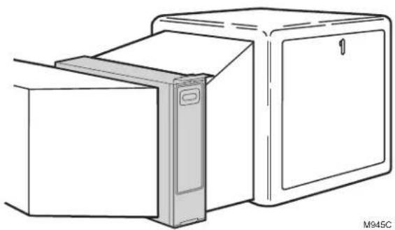
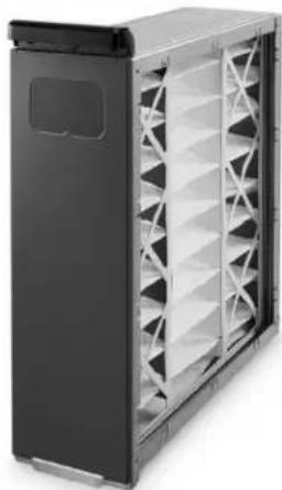
INCLUDED IN THIS BOX
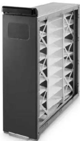
natural_image
Exterior view of a black server rack unit with ventilation grilles (no text or symbols visible)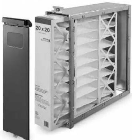
natural_image
Exterior view of a modular air vent unit with ventilation grilles and a black door (no visible text or symbols)Tools needed to install Enhanced Air Cleaner
Standard screwdriver
→ Phillips screwdriver
Metal cutter
Drill
→ Duct Sealant
Replacement Air Filters
| Filter Size (in.) | Part Number | |
| F100 - MERV 11 F200 - MERV 13 | ||
| 16 x 20 FC100A1003 | FC200E1003 | |
| 16 x 25 FC100A1029 | FC200E1029 | |
| 20 x 12.5 FC100A1052 N/A | ||
| 20 x 20 FC100A1011 | FC200E1011 | |
| 20 x 25 FC100A1037 | FC200E1037 | |
| 21.5 x 27.5 FC100A1045 N/A | ||
| 25 x 20 | FC100A1037 FC200E1037 | |
| 25 x 22 | FC100A1037 FC200E1037 | |
| Media Air Cleaner Size (in.) | F100 Media Air Cleaner w/ MERV 11 Filter | F200 Media Air Cleaner w/ MERV 13 Filter |
| 16 X 25 F100F1625 | F200F1625 | |
| 16 X 20 F100F1620 | F200F1620 | |
| 20 X 25 F100F2025 | F200F2025 | |
| 20 X 20 F100F2020 | F200F2020 | |
| 25 X 22 F100F2051 | N/A | |
| 25 X 20 F100F2044 | N/A | |
What to Expect From Your Media Air Cleaner
Congratulations for selecting the Media Air Cleaner for your home comfort system! The Media Air Cleaner captures and removes a significant amount of the air-borne particles from the air circulated through the high-efficiency pleated media filter. The Media Air Cleaner easily mounts in any position within the return air duct of any gas, oil, and electric forced warm air furnaces and to compressor cooling up to 5 tons.
Additionally, it requires no electrical connections or maintenance beyond periodic media filter replacement.
When Installing this Product...
- Read these instructions carefully. Failure to follow them could damage the product or cause a hazardous condition.
- Check the rating given in the instructions and on the product to make sure the product is suitable for your application.
- Installer must be a trained, experienced service technician.
- After installation is complete, check out product operation as provided in these instructions.
How it Works
The filter in your Media Air Cleaner is made up of a web of fibers. As air passes through the Media Air Cleaner, particulates such as dust, pollen, dander, mold, and bacteria collide with the fibers in the filter and become trapped. Meanwhile, the clean air is allowed to continue through your heating and cooling system and into your home. The particle removal efficiency of the Media Air Cleaner can be found in the Specification section of this manual.
Application Considerations
The Media Air Cleaner is designed to work with gas, oil, and electric forced warm air furnaces and with compressor cooling. It can also be used with heat pumps if the filter is changed regularly to prevent excessive pressure drop. The Media Air Cleaner is not recommended for applications where pressure drop may be critical.
Models
F100F Media Air Cleaner includes cabinet, access door and MERV 11 pleated media filter.
F200F Media Air Cleaner includes cabinet, access door and MERV 13 pleated media filter.
Air Conditioning
Mount the media air cleaner upstream of the evaporator coil in a cooling system. The filter will help to keep the coil clean and reduce maintenance.
Humidifiers
The media air cleaner is compatible with humidifiers. Avoid applications where water mist will reach the media. If an atomizing humidifier is used, the media filter will require replacement more often because of minerals in the water.
UV Lights
Germicidal UV lights can cause degradation of the media filter. The UV light should be located out of line of sight or a minimum of 3 feet from the filter. Otherwise the filter may need to be replaced more frequently.
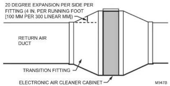
Transitions
For most efficient air cleaning, spread airflow evenly across the face of the media. If the duct is a different size than the media air filter cabinet, gradual transitions are required. Follow these guidelines when fabricating:
- Use gradual transitions to reduce air turbulence and increase efficiency.
- Use no more than 20 degrees (about 4 in. per running ft. [100 mm per 300 linear mm]) of expansion on each side of a transition fitting.
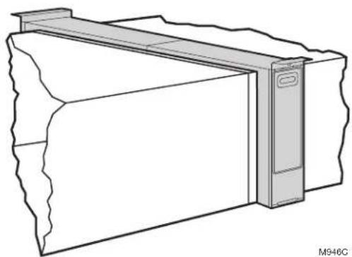
Turning Vanes
If the media air cleaner is installed next to an elbow or angle fitting, add turning vanes inside the angle to distribute airflow more evenly across the face of the media. See middle figure.
Sheetmetal
The media air cleaner is adaptable to all new or existing forced air heating and cooling systems used in residential applications. Transitions or turning vanes may be required in some applications for effective media air cleaner operation.
Offsets
If the duct connection to the furnace in a side installation allows less than 7 in. (178 mm) for mounting media air cleaner cabinet, attach an offset to the elbow. See bottom figure at right.
DUCT SIZE CHANGED GRADUALLY TO PREVENT TURBULENCE.
text_image
20 DEGREE EXPANSION PER SIDE PER FITTING (4 IN. PER RUNNING FOOT [100 MM PER 300 LINEAR MM]) RETURN AIR DUCT TRANSITION FITTING ELECTRONIC AIR CLEANER CABINET M947B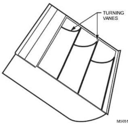
text_image
TURNING VANES M5651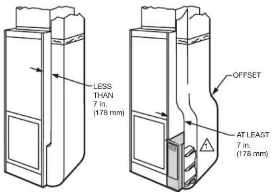
text_image
LESS THAN 7 in. (178 mm) OFFSET AT LEAST 7 in. (178 mm)1 REQUIRED TURNING VANES HELP DISTRIBUTE AIRFLOW EVENLY. M946C
Important Installation Requirements
Failure to comply with these requirements will result in voided warranty, improper installation, and service callbacks.
Personal Safety
- Wear safety glasses while installing the unit.
- Do not cut into any air conditioning or electrical line.
- Follow professional safety standards and all local codes for plumbing, electrical, and mechanical considerations.
Before Mounting
- Using the figure on the cover and the lists on the inside cover, make sure that you have all the components for your Media Air Cleaner and the tools to install it.
- Ensure airflow direction through the Media Air Cleaner matches the arrows on the filter cartridge. The arrows should point in the direction of the airflow.
- Choose a location that is readily accessible for checking and replacing the filter. Allow at least 26 in. (660 mm) clearance in front of the unit for removal of the cartridge.
• Install the media air filter where the temperature will not exceed the ratings in the Specifications. - Do not mount in the supply air duct.
NOTE: Generally, the best location is in the return air duct next to the blower compartment so the media air cleaner can help to keep the blower motor and evaporator coils clean.
If Replacing an Old Air Cleaner
If the Media Air Cleaner is not identical in size and shape to the existing air cleaner, before performing a retrofit installation, you might need to add duct transitions to ensure a smooth air flow.
For optimum system performance, replace the filter every six months (before heating season and before cooling season). Adjust the schedule to your needs, but replace the filter at least once per year.
Choosing a Mounting Position
The Media Air Cleaner mounts in any position within the return air duct, usually next to the furnace blower compartment, but the arrow on the cartridge must point in the same direction as the airflow. See Figs. 1-8 for proper location of the media air cleaner for a variety of furnace installations.
NOTE: The media air cleaner cabinet is sturdy enough to easily support the weight of the furnace and evaporator coil.
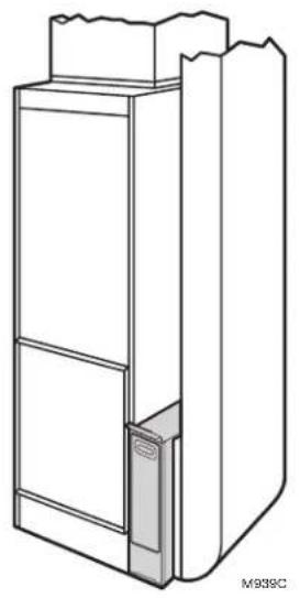
natural_image
Technical line drawing of a cabinet or enclosure structure with no visible text or symbolsFig. 1. Highboy furnace with side installation. Media air filter is mounted vertically where return enters side inlet of furnace.
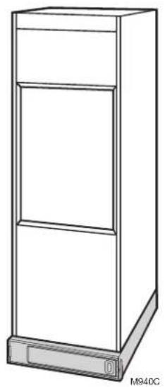
natural_image
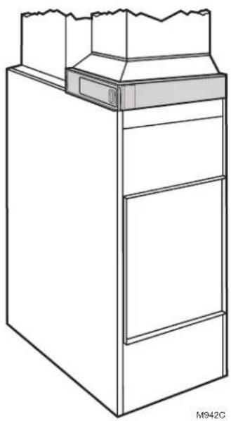
Line drawing of a three-tiered storage cabinet with a base and door, labeled M940C (no text or symbols on the cabinet itself)Fig 2. Highboy furnace, with installation beneath furnace. Media air cleaner is mounted horizontally where return enters from below.
natural_image
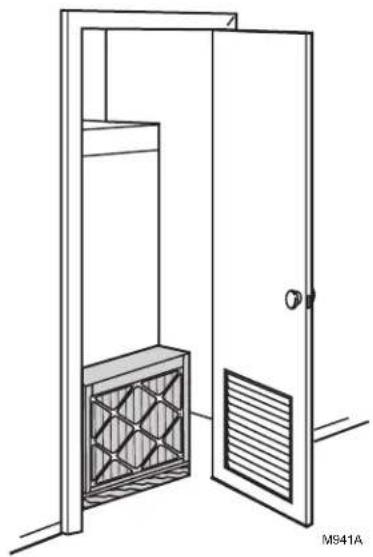
Line drawing of a door with a mesh vent and ventilation grille (no text or symbols)Fig. 3. Highboy furnace, with closet installation. Media air cleaner is mounted vertically on furnace between furnace and louvered return air opening in closet door.
Before beginning Mounting:
☐ I have chosen an installation location that meets the requirements on pages 5 through 6.
natural_image
Line drawing of a cabinet or storage unit with no visible text, numbers, or symbolsFig. 4. Lowboy furnace, with media air cleaner mounted horizontally in return plenum just above furnace and opposite heating plenum.
natural_image
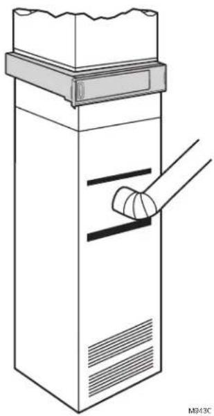
Line drawing of a mechanical device with a handle and a curved component inserted (no text or symbols)Fig. 5. Counterflow furnace, with media air cleaner mounted horizontally in return duct or plenum just above furnace.
natural_image
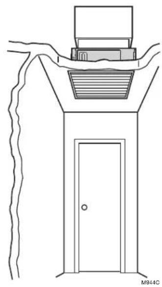
Line drawing of a door with a vent and roof, no text or symbols presentFig. 6. Central fan installation, with media air cleaner mounted horizontally in central return duct.
natural_image
Line drawing of a refrigerator with a door and cabinet, no text or symbols presentFig. 7. Horizontal furnace, with media air filter mounted vertically in return duct near furnace.
natural_image
Technical line drawing of a mechanical or architectural component with layered structure and mounting bracket (no text or symbols)Fig. 8. Two or more media air cleaners used in a high capacity system.
Mounting the Media Air Cleaner
The following procedure describes a typical side installation on an existing highboy furnace (Fig. 1). Alternate procedures are noted as appropriate. Other changes in installation procedures may be necessary to complete your installation.
NOTE: Before starting the installation, remove and discard the existing furnace filter (if used). Thoroughly clean the blower compartment. If possible, power vacuum the ductwork to remove accumulated dust in an occupied home or remove construction dirt in a new home. The media air cleaner cannot remove dirt that has settled in the blower compartment and distribution ducts.
STEP ONE: Review the Installation Plan
Temporarily place the cabinet on the floor, oriented as it will be when installed. Insert and remove the cartridge to make sure the plan allows adequate clearance for easy removal and replacement of the cartridge.
STEP TWO: Fasten the Cabinet to the Furnace
a. Align the cabinet with the return air opening.
b. Place blocks under the cabinet, as necessary, to make sure the unit sits securely.
c. Create an opening in the furnace to match the cabinet opening.
d. Attach the cabinet securely to the furnace. Attach the unit directly or fit a starting collar in the furnace opening. Either drill holes and fasten with sheetmetal screws or rivets, or use slip joints. If you are drilling holes, use a locking pliers to help hold the unit in place during drilling.
STEP THREE: Install Turning Vanes
Install turning vanes to help distribute air equally over the full surface of the upstream side of the media. Install them whenever an abrupt 90 degree elbow is installed directly against the media air cleaner cabinet.
STEP FOUR: Fasten Cabinet to Ductwork
Fasten side of cabinet to the ductwork using sheet-metal screws, rivets, or slip joints, as appropriate.
STEP FIVE: Connect Ductwork
a. Connect the vertical duct section to the elbow. If the vertical drop of the duct is less than 7 in. (178 mm) from the side of the furnace, shorten the horizontal trunk or attach an offset fitting to the elbow.
b. When ductwork is properly aligned, connect the vertical duct to the horizontal trunk.
STEP SIX: Seal Joints
Seal all joints in the return air system between the media air filter and the furnace to prevent dust from entering the clean airstream.
STEP SEVEN: Install Filter Cartridge
Slide the filter cartridge into the cabinet, making sure the arrow on the cartridge points in the direction of air flow. Replace access door. Insert the tab on the bottom of the door into the slot in the cabinet. Swing the door closed and press it into place.
Checkout
Visually check the installation and make sure that:
- Airflow is in the direction of the arrow on the media air filter cartridge.
- Turning vanes and transitions, if used, are properly installed.
- Joints in sheetmetal between media air filter and furnace are sealed.
- All sheetmetal connections are complete.
- Original furnace filter has been removed and blower compartment is cleaned.
When you have verified that checkout has been completed:
- Replace any access doors removed during the Installation or Checkout.
- Run the furnace or cooling system through one complete cycle to make sure the system operates as desired.
Maintenance
The media filter must be replaced when pressure drop across the media filter reaches 0.5 in. w.c. (0.1 kPa), or at least annually. If the media air cleaner is installed downstream from an atomizing humidifier or if the installation includes both heating and cooling, more frequent replacement may be necessary. Clogged media must be replaced promptly to avoid restricting airflow and reducing efficiency of the heating/cooling system. Record the replacement date in the space provided on the replacement media filter.
Specifications
The specifications in this publication do not include normal manufacturing tolerances; therefore, an individual unit may not exactly match the listed specifications. This product is tested and calibrated under closely controlled conditions, and some minor differences in performance can be expected if those conditions are changed.
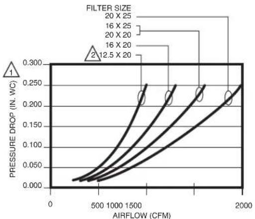
F100 Specifications
MERV Rating*: MERV 11
Static Pressure Drop: 0.23 (in. w.c.) at 500 FPM Efficiency Definition*:
Small Particles: E1 = 0.3 to 1.0 microns = 32%
Medium Particles: E2 = 1.0 to 3.0 microns = 72%
Large Particles: E3 = 3.0 to 10.0 microns = 96%
line
| AIRFLOW (CFM) | FILTER SIZE 20 X 25 | FILTER SIZE 16 X 25 | FILTER SIZE 20 X 20 | FILTER SIZE 16 X 20 | FILTER SIZE 12.5 X 20 | | ------------- | ------------------- | ------------------- | ------------------- | ------------------- | --------------------- | | 0 | 0.000 | 0.000 | 0.000 | 0.000 | 0.000 | | 500 | ~0.050 | ~0.040 | ~0.030 | ~0.025 | ~0.020 | | 1000 | ~0.150 | ~0.120 | ~0.100 | ~0.080 | ~0.060 | | 1500 | ~0.250 | ~0.220 | ~0.200 | ~0.180 | ~0.160 | | 2000 | ~0.300 | ~0.280 | ~0.260 | ~0.240 | ~0.220 |
WHEN FIRST INSTALLED. PRESSURE DROP INCREASES AS FILTER BECOMES LOADED. REPLACE FILTER WHEN PRESSURE DROP REACHES 0.5 IN. WC. (0.1 kPa).

AVAILABLE ONLY IN UNITED STATES.
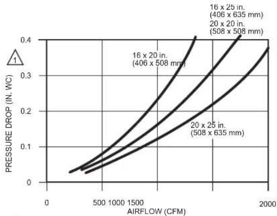
F200 Specifications
MERV Rating*: MERV 13
Static Pressure Drop: 0.3 (in. w.c.) at 500 FPM
Efficiency Definition*:
Small Particles: E1 = 0.3 to 1.0 microns = 63%
Medium Particles: E2 = 1.0 to 3.0 microns = 91%
Large Particles: E3 = 3.0 to 10.0 microns = 99%
line
| AIRFLOW (CFM) | PRESSURE DROP (IN. WC) | | ------------- | ---------------------- | | 406 x 508 | 0.0 | | 508 x 635 | 0.0 | | 406 x 508 | 0.1 | | 508 x 635 | 0.2 | | 406 x 635 | 0.3 | | 508 x 508 | 0.4 |
WHEN FIRST INSTALLED. PRESSURE DROP INCREASES AS FILTER BECOMES LOADED. REPLACE FILTER WHEN PRESSURE DROP REACHES 0.5 IN. WC. (0.1 kPa). M13662
* Minimum Efficiency Reporting Value (Media Filters Only)
* Efficiency ratings are based on American Society of Heating, Refrigerating and Air-Conditioning Engineers Standard 52.2-1999.
Dimensions
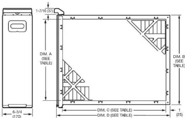
text_image
1-7/16 (37) DIM. A (SEE TABLE) DIM. B (SEE TABLE) 6-3/4 (170) DIM. C (SEE TABLE) DIM. D (SEE TABLE) 1 (25)| F100F SIZE | DIM. A | DIM. B | DIM. C | DIM. D | |||||
| IN. | MM | IN. MM | IN. MM | IN. MM | IN. | MM | |||
| 16 X 25 | 406 X 635 | 14-1/4 | 362 | 16-1/4 | 413 | 23-1/4 | 591 | 25-7/16 | 846 |
| 16 X 20 | 406 X 508 | 14-1/4 | 362 | 16-1/4 | 413 | 18-1/4 | 457 | 20-7/16 | 519 |
| 20 X 25 | 508 X 635 | 18-1/4 | 464 | 20-3/16 | 513 | 23-1/4 | 591 | 25-7/16 | 646 |
| 20 X 20 | 508 X 508 | 18-1/4 | 464 | 20-3/16 | 513 | 18-1/4 | 457 | 20-7/16 | 519 |
| 25 X 20 | 635 X 508 | 23-1/8 | 587 | 25-3/16 | 640 | 18-1/4 | 457 | 20-3/4 | 527 |
| 25 X 22 | 635 X 559 | 23-1/8 | 587 | 25-3/16 | 640 | 20-1/4 | 514 | 22-3/4 | 578 |
M37054A
Temperature Rating
-40^ to +140^ (-40^ to +60^)
Approvals
Underwriters Laboratories, Inc.:
Listed to UL 900, Class 2.
Replacement Air Filters
| Filter Size (in.) | Part Number | |
| F100 - MERV 11 | F200 - MERV 13 | |
| 16 x 20 | FC100A1003 | FC200E1003 |
| 16 x 25 | FC100A1029 | FC200E1029 |
| 20 x 12.5 | FC100A1052 | N/A |
| 20 x 20 | FC100A1011 | FC200E1011 |
| 20 x 25 | FC100A1037 | FC200E1037 |
| 21.5 x 27.5 | FC100A1045 | N/A |
| 25 x 20 | FC100A1037 | FC200E1037 |
| 25 x 22 | FC100A1037 | FC200E1037 |

resideo
Resideo Inc., 1985 Douglas Drive North
Golden Valley, MN 55422
www.resideo.com
68-0239EF-13 M.S. Rev. 11-19 | Printed in United States

INCLUS DANS LA BOÎTE
natural_image
Exterior view of a black server rack with ventilation grilles (no text or symbols visible)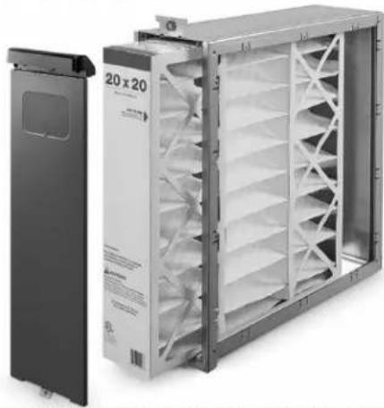
natural_image
Exterior view of a modular air conditioner unit with fan array and control panel (no visible text or symbols)natural_image
Technical line drawing of a cabinet or enclosure structure with no visible text or symbolsnatural_image
Line drawing of a three-tier refrigerator cabinet (no text or symbols)natural_image
Line drawing of a door with a mesh vent and ventilation grilles (no text or symbols)natural_image
Line drawing of a cabinet or storage unit with no visible text, numbers, or symbolsnatural_image
Line drawing of a mechanical device with a handle and a curved component inserted (no text or symbols)natural_image
Line drawing of a door with a vent, mounted on a wall, and a curved roof (no text or symbols)natural_image
Line drawing of a refrigerator with a door and front panel, no text or symbols presentnatural_image
Line drawing of a wall-mounted air conditioner unit with a side panel and wavy insulation material (no text or symbols)Grosses particules : E3 = 3,0 à 10,0 microns = 99%
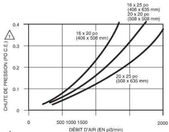
line
| Débit D'AIR (EN pi3/min) | CHUTE DE PRESSION (PO C.E.) | | ------------------------ | --------------------------- | | 0 | 0.0 | | 500 | 0.1 | | 1000 | 0.2 | | 1500 | 0.3 | | 2000 | 0.4 |1 LORS DE LA PREMIÈRE INSTALLATION. LA CHUTE DE PRESSION AUGMENTE À MESURE QUE LE FILTRE SE REMPLISSE. REMPLACER LE FILTRE LORSQUE LA CHUTE DE PRESSION ATTEINT 0,5 PO C.E. (0,1 kPa). MF13962
Underwriters Laboratories Inc.:
Resideo Inc., 1985 Douglas Drive North
Golden Valley, MN 55422
www.resideo.com