
UV2400XBAL1/U - Air purifier HONEYWELL - Free user manual and instructions
Find the device manual for free UV2400XBAL1/U HONEYWELL in PDF.

| Product Type | UV air purifier for duct installation |
| Model | UV2400U (UV2400U5000 with odor absorber, UV2400U1000 without) |
| Brand | Honeywell Home (manufactured by Resideo Technologies) |
| UV Lamp | 16 W, germicidal |
| Power Supply | 24 V AC, 16 VA (ballast included) |
| Frequency | 50-60 Hz |
| Main Function | UV disinfection of evaporator coils and duct surfaces, reduction of mold and bacteria |
| Odor Absorption | AirBRIGHT™ option (included on UV2400U5000, available separately) |
| Installation | On supply or return duct, internal or external mounting, requires a 2-inch (5 cm) hole |
| Approximate Dimensions (base) | Approximately 12 x 12 x 5 cm (excluding handle) |
| Weight | Approximately 350 g (ballast included) |
| Lamp Life | 1 year (loses effectiveness after, although still visible) |
| Maintenance | Annual lamp replacement, debris cleanup in case of breakage |
| Safety | UV protection (duct mounting switch, viewing window), disconnect before maintenance, gloves required |
| Replacement Parts | Lamp UV2400XLAM1, ballast UV2400XBAL1, absorber UV2400XPCO1, panel adapter UV2400XDBA1 |
| Warranty | 5-year limited (parts and labor) |
| Mercury Content | Yes (in sealed UV lamp), proper disposal required |
Frequently Asked Questions - UV2400XBAL1/U HONEYWELL
User questions about UV2400XBAL1/U HONEYWELL
0 question about this device. Answer the ones you know or ask your own.
Ask a new question about this device
Download the instructions for your Air purifier in PDF format for free! Find your manual UV2400XBAL1/U - HONEYWELL and take your electronic device back in hand. On this page are published all the documents necessary for the use of your device. UV2400XBAL1/U by HONEYWELL.
USER MANUAL UV2400XBAL1/U HONEYWELL
natural_image
Technical line drawing of a mechanical assembly with no visible text or symbolsInstallation Instructions
UV2400U Air Purifier
with AirBRIGHT™ Odor Absorption
UV2400U5000 with AirBRIGHT™, UV2400U1000 without AirBRIGHT™, Read before installing
Input: 4 V=, 0.8 A, 50-60 Hz, Pf .64
Before Installing this Product
Read these instructions carefully; failure to follow them could damage the product and cause a hazardous situation.
Installer must be a trained, experienced service technician.
WARNING: UV Light Hazard.
Harmful to bare skin and eyes. Can cause temporary or permanent loss of vision. Never look at lamps while illuminated.
- To prevent exposure to ultraviolet light, disconnect power to the ultraviolet air treatment system before servicing any part of the heating/air conditioning system.
• View illumination only through lamp handle or sight glass. - Do not attempt to bypass duct mount switch.
- Do not attempt to open housing; unit is sealed to prevent ultraviolet light exposure.
CAUTION: Personal Injury Hazard. HVAC power supply can cause electrical shock.
Disconnect HVAC power supply before installing, cleaning or replacing ultraviolet lamp(s).
CAUTION: Breakable Glass Hazard. Can cause personal injury.
- Be careful when inserting lamp(s) into lamp base.
- Wear protective gloves when handling lamp(s).
CAUTION: Personal Injury Hazard. Power supply can cause electrical shock.
- Disconnect power supply before cleaning or replacing ultraviolet lamp(s).
- Do not open base unit or lamp handle; there are no user-serviceable components inside.
CAUTION: UV Lamp Burn Hazard. Harmful to bare skin. Can cause severe burns.
- Disconnect power 15 minutes before removing ultraviolet lamp(s).
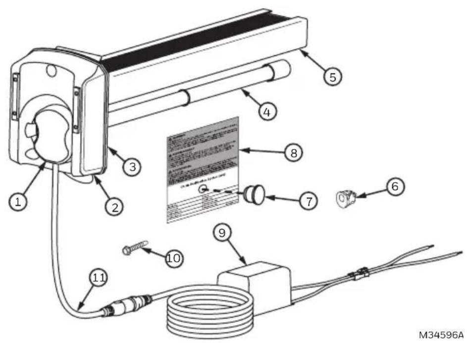
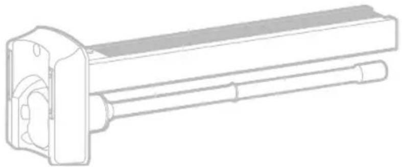
Parts Included
- UV lamp handle
- Base
- Foam Gasket
- 16W UV lamp
- AirBRIGHT™ Odor Absorber (included in UV2400U5000 only)
- Bushing
- Sight Glass
- Warning sticker
- 24 VAC Ballast
- Self Tapping Screws (3)
- Power Cord
- Wire connectors (not pictured)
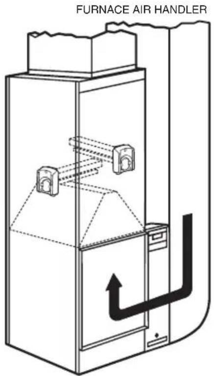
Typical Mounting Locations
We recommend the UV Air Purifier be installed on the supply side duct 3–5 inches above the A-coil, but it can also be installed on the return side if necessary. See Figures 1 and 2.
The germicidal UV light should be positioned to shine on the surfaces that are prone to mold growth like the A-coil, or be placed in an open area of the return duct where there are long straight runs.
WARNING: Do not mount device in location that allows ultraviolet light to be seen after installation other than by the UV protected lamp handle or sight glass.
Important: Some materials inside the HVAC system (including filter media, flex duct, wiring etc.) may not be UV light resistant. Cover materials affected by UV light with UV shielding or reflective tape.
The AirBRIGHT™ Odor Absorber unit should be oriented so that the air flows past the UV Light first then into the AirBRIGHT Odor Absorber.
natural_image
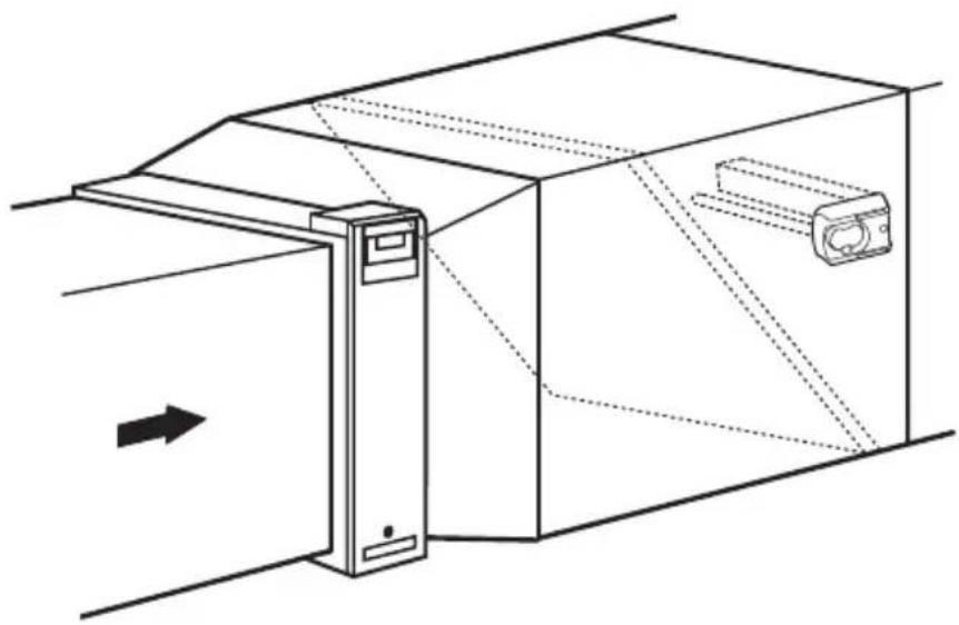
Technical line drawing of a mechanical assembly with a door and housing, showing internal components and directional arrows (no text or symbols)M34597
Fig. 1. Supply Side installation. Airflow depicted by arrows.
M34621
Fig. 2. Return Side installation. Airflow depicted by arrows.
Option 1
Internal Mounting
IMPORTANT
Turn off main power source before installation. Model information is printed on the Power Unit cover.
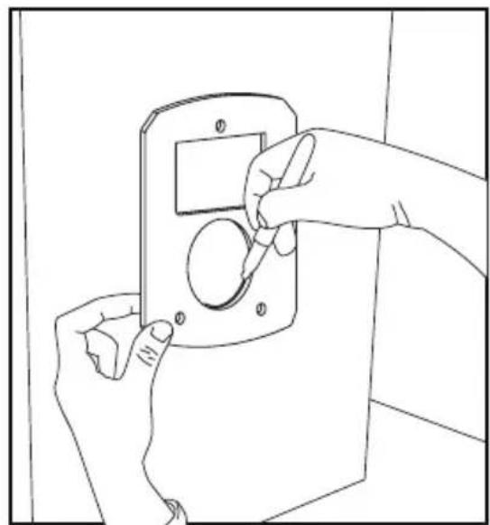
- Unfasten panel to gain access to mounting location
- Determine the optimal position for placement of the Air Purifier.
- If necessary, use a utility knife to cut the insulation on the inside of the duct.
- Clean surface of glue, dust, etc.
natural_image
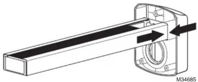
Line drawing of a hand holding a knife with a serrated blade, no text or symbols present- Push the AirBRIGHT™ Odor Absorber into the base until the two tabs on the side click into place.
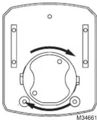
- Rotate the lamp handle clockwise until it snaps in place.
natural_image
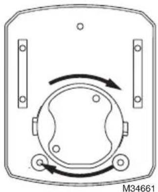
Diagram of a device casing with rotating components and mounting holes (no text or symbols)- Place the magnetic bars on the base directly on the clean metal surface.
natural_image
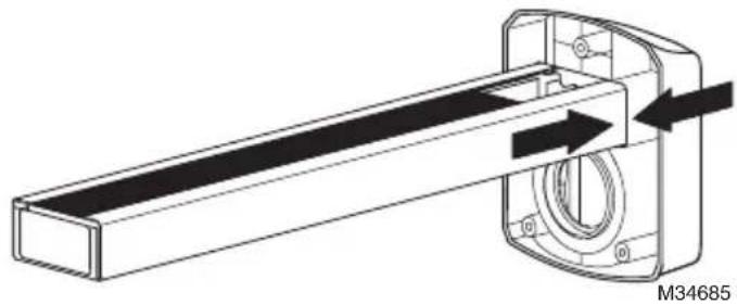
Technical line drawing of a mechanical device with a flanged base and cylindrical shaft (no text or symbols)-
Use foil tape to close the cut in the insulation as needed.
-
Create a 5/8 (0.625) in. hole in the duct and pass the cord through it. Clip the bushing provided onto the cord at a point close to the hole. Plug the hole with the bushing.
natural_image
Line drawing of a cable connector with a black circular end cap, shown against a plain background (no text or symbols)-
Secure access panel to the duct work.
-
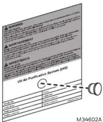
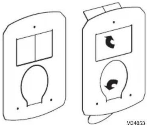
Find a suitable location on the outside of the duct-work near the UV Lamp installation and apply the warning/lamp replacement sticker.
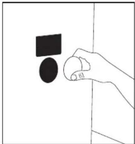
- Drill a 1/2 in. hole through the circle on the sticker. Press the UV sight glass into hole.
Option 2
External Mounting for Metal Duct Applications
- Use the gasket to mark the duct openings. Cut and remove openings, making sure to cut 1/8-inch outside of the markings to create enough room for the product. If using a hole saw to cut circular opening, use a 2-inch diameter bit.
natural_image
Line drawing of hands installing or adjusting a door panel (no text or symbols)
natural_image
Simple line drawing of a hand holding a circular object with a black square above it, against a plain background (no text or symbols)- Push the AirBRIGHT™ Odor Absorber into the base until the two tabs on the side click into place.
natural_image
Technical line drawing of a mechanical assembly with directional arrows indicating motion (no text or symbols)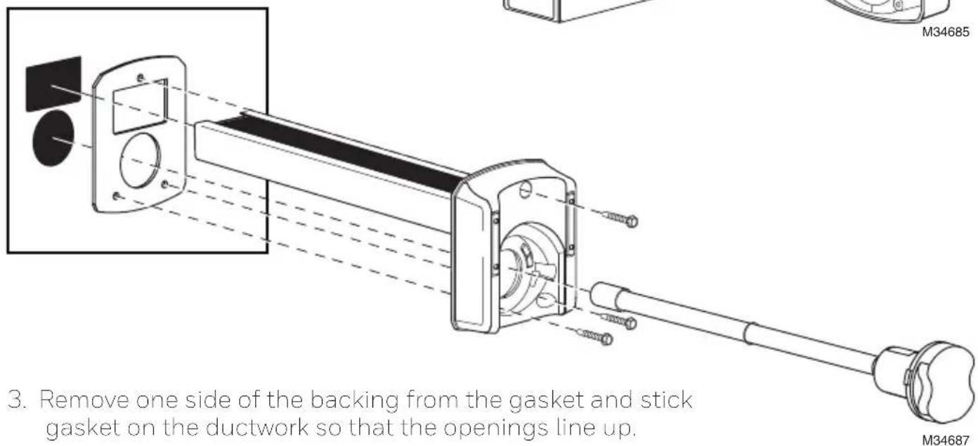
- Peel away the other side of the backing on the gasket and insert AirBRIGHT™ into the duct until the base sticks securely to the gasket.
- Secure the base to the ductwork using self-tapping screws.
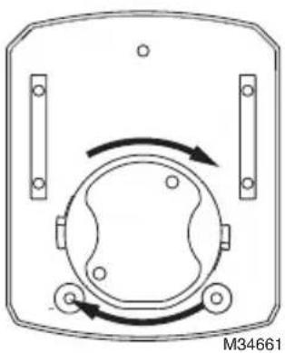
- Insert lamp into base and turn handle clockwise to lock in place.
natural_image
Diagram of a mechanical or electrical component with circular body and directional arrows, no readable text or symbols- Find a suitable location on the outside of the duct-work near the UV Lamp installation and apply the warning/lamp replacement sticker.
Option 3
Duct Board Mounting: For Duct Board Applications Only
- Use the gasket to mark the duct openings. Cut and remove openings, making sure to cut 1/8-inch outside of the markings to create enough room for the product. If using a hole saw to cut circular opening, use a 2-inch diameter bit.
natural_image
Line drawing of hands installing or adjusting a wall-mounted device (no text or symbols)
natural_image
Hand holding a circular object with a black square above it, against a plain background (no text or symbols)M34604
- Push the AirBRIGHT™ Odor Absorber into the base until the two tabs on the side click into place.
natural_image
Technical line drawing of a mechanical assembly with directional arrows indicating motion (no text or symbols)- Bend metal tabs of duct board adapter over the holes cut in the duct board.
natural_image
Two identical electronic device diagrams showing front and side views with internal components and directional arrows (no text or symbols)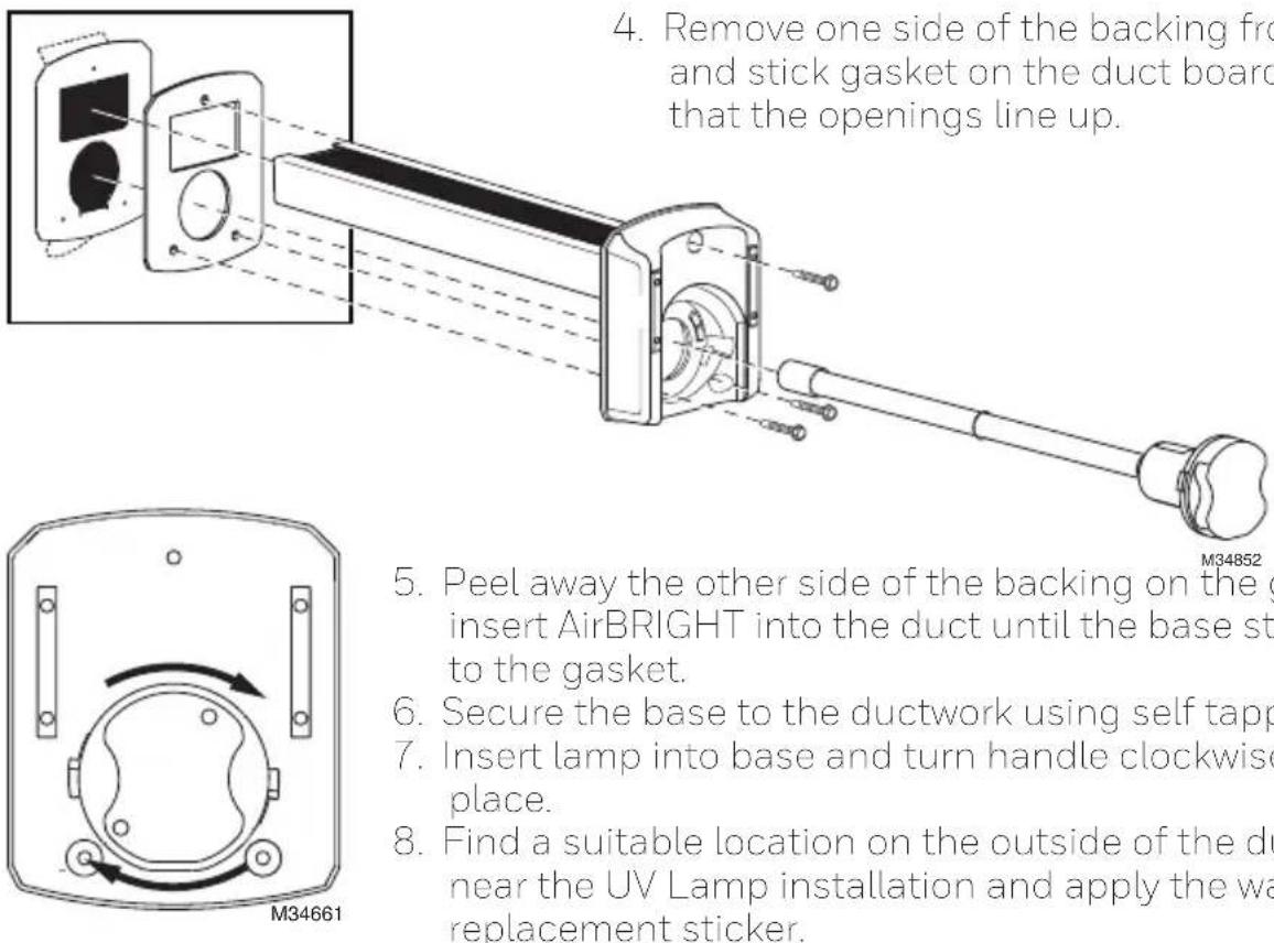
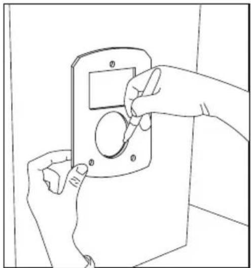
- Remove one side of the backing from the gasket and stick gasket on the duct board adapter so that the openings line up.
natural_image
Diagram of a device with rotating components and directional arrows, no text or symbols present- Peel away the other side of the backing on the gasket and insert AirBRIGHT into the duct until the base sticks securely to the gasket.
- Secure the base to the ductwork using self tapping screws.
- Insert lamp into base and turn handle clockwise to lock in place.
- Find a suitable location on the outside of the duct-work near the UV Lamp installation and apply the warning/lamp replacement sticker.
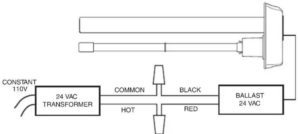
Power Supply Installation
- Find a suitable location for the power supply and mount using the self-tapping screws.
- Use the wiring diagram on the next page to connect to power.
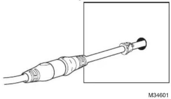
- When all the other components are properly installed connect the UV lamp cable to the power supply cable.
• Make sure the flanges are aligned and then push the connectors firmly together. A tight connection ensures a proper water-resistant seal. See image at right.
- Turn on the power and use the lamp handle or sight glass to confirm that the UV Lamp is operating.

Power Supply Wiring
WARNINGS:
- Draws 16 VA, do load calculation to determine if a separate transformer is needed.
- Systems with high 24 VAC loads may require the installation of a separate 24 VAC transformer to power the UV light.
- Always use a separate 24 VAC transformer with "communicating" air systems.
flowchart
graph LR
    A["CONSTANT 110V"] --> B["24 VAC TRANSFORMER"]
    B --> C["COMMON"]
    B --> D["HOT"]
    B --> E["BLACK"]
    E --> F["BALLAST 24 VAC"]
    F --> G["Red"]
    G --> H["Ground"]
NOTE: IMPORTANT! MUST BE WIRED TO CONSTANT POWER. DO NOT CONNECT TO BLOWER RELAY. M34605
Maintenance
Note: Lamps should be replaced every year. UV lamps will continue to emit visible light but lose germicidal effectiveness after approximately one year.
Changing UV Lamp
- Disconnect the power to your heating and cooling system.
- Unplug or turn off power to your UV System and allow the lamp to cool for at least 15 minutes.
- Rotate the lamp handle counterclockwise, as shown below, and gently pull the lamp handle to remove the lamp.
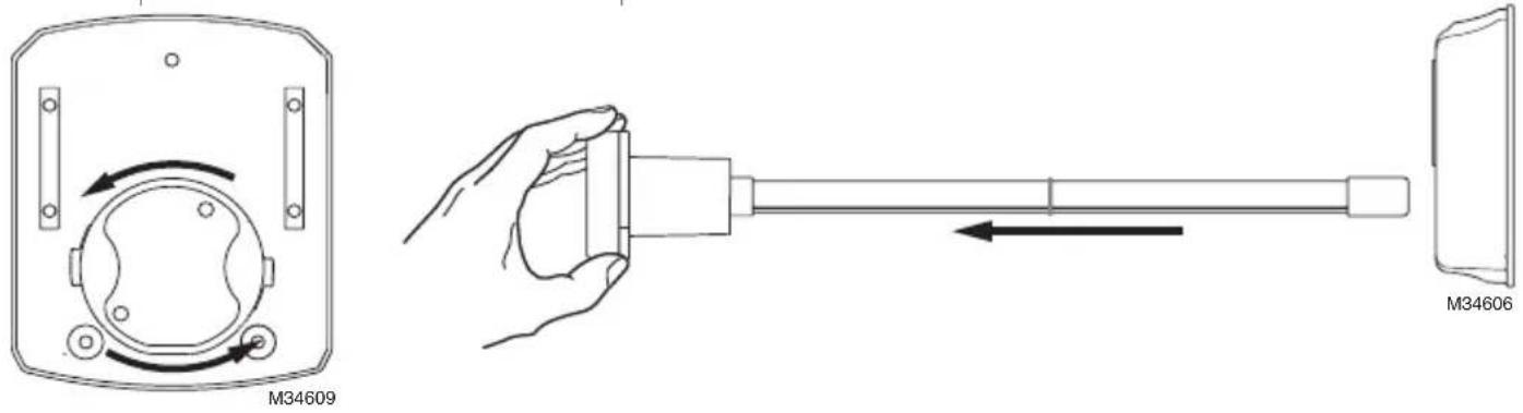
Replacing UV Lamp
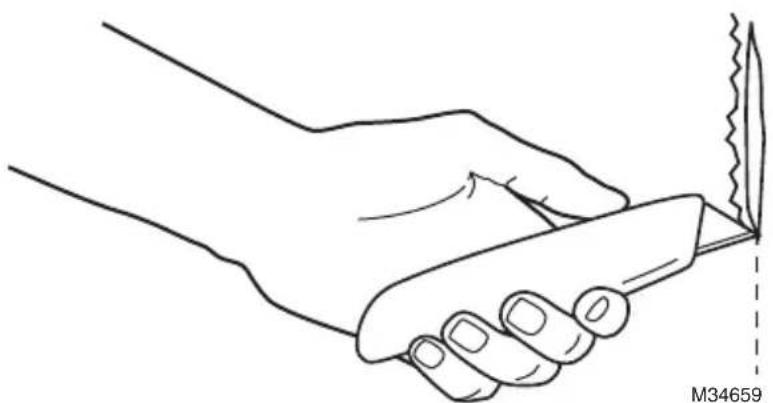
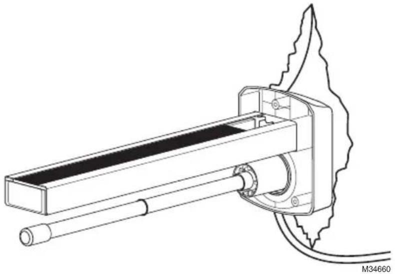
Grasp the SnapLamp ^™ handle in one hand and the base of the lamp glass in the other and pull straight apart.
natural_image
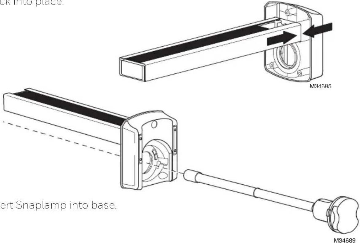
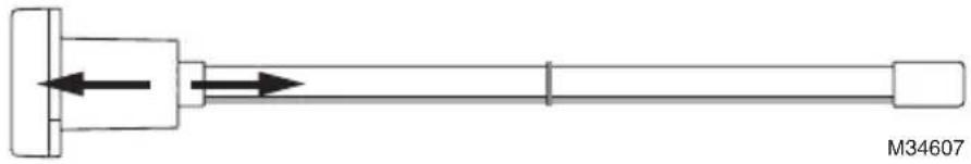
Pure mechanical shaft diagram without any text, numbers, or symbolsInsert the new lamp glass into the SnapLamp ^™ handle by aligning the key and pushing straight together.
natural_image
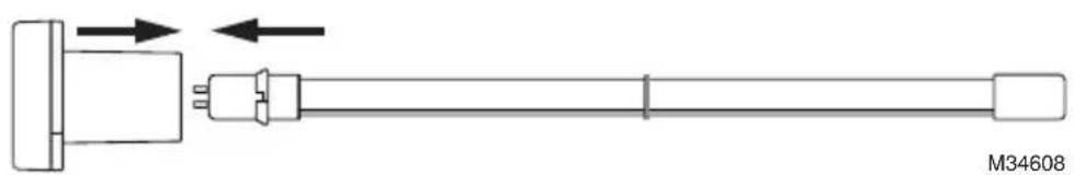
Pure mechanical diagram showing a shaft connected to a connector with directional arrows, no text or symbols present.Replace SnapLamp ^TM in Base
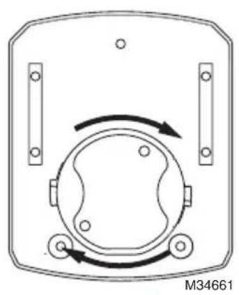
Rotate the lamp handle clockwise until it snaps into place.
natural_image
Diagram of a mechanical or electrical component with circular and rectangular features, no visible text or symbolsMERCURY NOTICE
This device contains mercury in the sealed ultraviolet lamp(s). Do not place your used lamp(s) in the trash. Dispose of properly.
Broken Lamp Cleanup and Disposal
Do not use a household vacuum. Sweep debris (phosphor/glass) into a plastic bag and dispose of properly. Contact your local waste management authority for instructions regarding recycling and the proper disposal of old lamp(s).
Note: Use of replacement UV lamps other than Honeywell Home approved lamps voids warranty.
Replacement Parts
UV2400U5000 - UV Air Purifier with AirBRIGHT™ Odor Absorption
UV2400U1000 - UV Air Purifier
UV2400XPCO1 - AirBRIGHT Odor Absorber
UV2400XBAL1 - Replacement Ballast
UV2400XLAM1 - Replacement Lamp
UV2400XDBA1 - Duct Board Adapter
Five-Year Limited Warranty
Resideo warrants this product, excluding battery, to be free from defects in workmanship or materials, under normal use and service, for a period of five (5) years from the date of first purchase by the original purchaser. If at any time during the warranty period the product is determined to be defective due to workmanship or materials, Resideo shall repair or replace it (at Resideo's option).
If the product is defective,
(i) return it, with a bill of sale or other dated proof of purchase, to the place from which you purchased it; or
(ii) call Resideo Customer Care at 1-800-468-1502. Customer Care will make the determination whether the product should be returned to the following address: Resideo Return Goods, 1985 Douglas Dr. N., Golden Valley, MN 55422, or whether a replacement product can be sent to you.
This warranty does not cover removal or reinstallation costs. This warranty shall not apply if it is shown by Resideo that the defect was caused by damage which occurred while the product was in the possession of a consumer.
Resideo's sole responsibility shall be to repair or replace the product within the terms stated above. RESIDEO SHALL NOT BE LIABLE FOR ANY LOSS OR DAMAGE OF ANY KIND, INCLUDING ANY INCIDENTAL OR CONSEQUENTIAL DAMAGES RESULTING, DIRECTLY OR INDIRECTLY, FROM ANY BREACH OF ANY WARRANTY, EXPRESS OR IMPLIED, OR ANY OTHER FAILURE OF THIS PRODUCT.
Some states do not allow the exclusion or limitation of incidental or consequential damages, so this limitation may not apply to you.
THIS WARRANTY IS THE ONLY EXPRESS WARRANTY RESIDEO MAKES ON THIS PRODUCT. THE DURATION OF ANY IMPLIED WARRANTIES, INCLUDING THE WARRANTIES OF MERCHANTABILITY AND FITNESS FOR A PARTICULAR PURPOSE, IS HEREBY LIMITED TO THE FIVE YEAR DURATION OF THIS WARRANTY. Some states do not allow limitations on how long an implied warranty lasts, so the above limitation may not apply to you.
This warranty gives you specific legal rights, and you may have other rights which vary from state to state. If you have any questions concerning this warranty, please write Resideo Customer Care, 1985 Douglas Dr, Golden Valley, MN 55422 or call 1-800-468-1502.

resideo
www.resideo.com
Resideo Technologies Inc.
1985 Douglas Drive North, Golden Valley, MN 55422
1-800-468-1502
69-2796EFS-04 M.S. Rev. 07-20 | Printed in United States
© 2020 Resideo Technologies, Inc. All rights reserved.
The Honeywell Home trademark is used under license from Honeywell International, Inc. This product is manufactured by Resideo Technologies, Inc. and its affiliates.
69-2796EFS-04
Honeywell Home


natural_image
Technical line drawing of a mechanical assembly with no visible text or symbolsnatural_image
Line drawing of a hand holding a knife with a knife tip, no text or symbols presentnatural_image
Diagram of a device casing with rotating components and mounting holes (no text or symbols)natural_image
Technical line drawing of a mechanical device with a flanged base and cylindrical shaft (no text or symbols)natural_image
Line drawing of a cable connector with a terminal connector, labeled M34601 (no text or symbols on the diagram itself)natural_image
Line drawing of hands installing or adjusting a door panel (no text or symbols)12
natural_image
Simple line drawing of a hand holding a small object near a black square and oval on a white background (no text or symbols)M34604
natural_image
Technical line drawing of a mechanical assembly with directional arrows indicating motion (no text or symbols)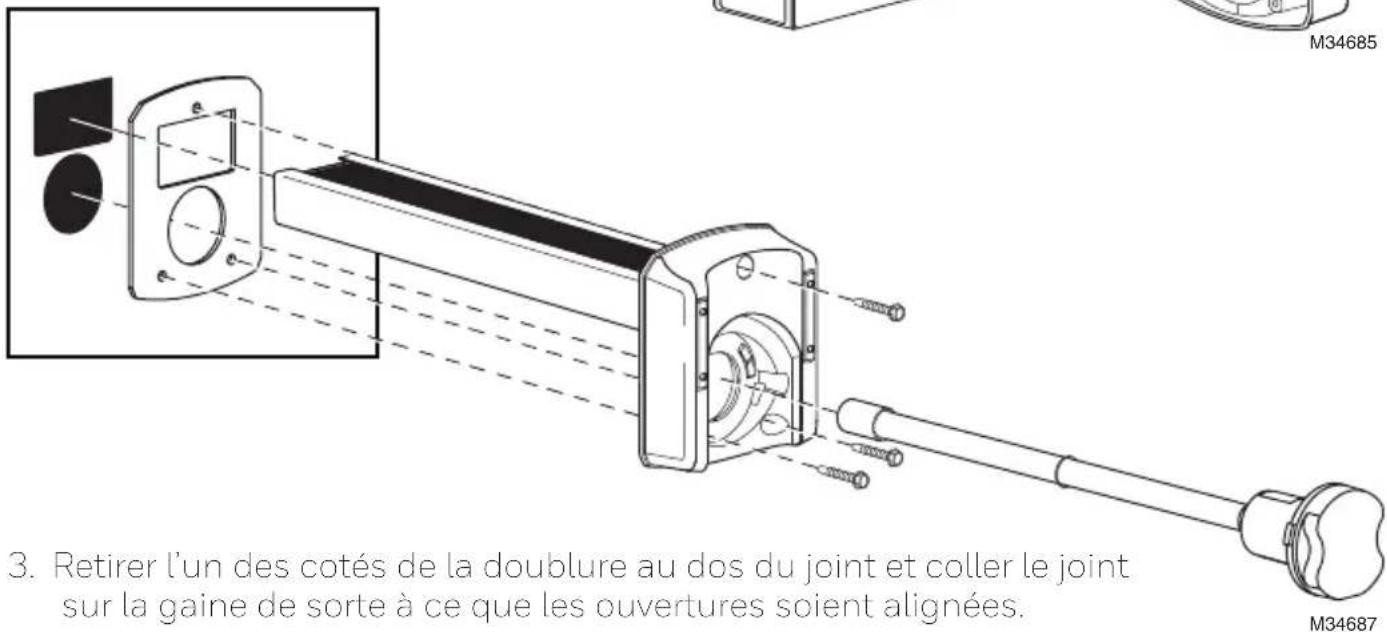
natural_image
Diagram of a mechanical component with rotational arrows indicating motion (no text or symbols)natural_image
Technical line drawing showing hands operating a device with a magnified view of the screen (no text or symbols)15
natural_image
Technical line drawing of a mechanical assembly with directional arrows indicating motion (no text or symbols)natural_image
Two identical electronic device diagrams showing front and side views with internal components and directional arrows (no text or symbols)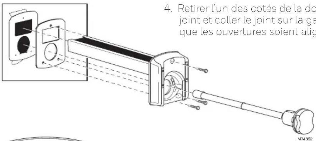
natural_image
Diagram of a mechanical or electrical component with circular features and directional arrows, no readable text or symbols.natural_image
Pure mechanical shaft diagram without any text, numbers, or symbolsnatural_image
Pure mechanical diagram showing a shaft connected to a connector with directional arrows, no text or symbols present.AVIS RELATIF AU MERCURE
natural_image
Diagram of a device with circular components and directional arrows, no readable text or symbolsResideo Technologies Inc.
1985 Douglas Drive North, Golden Valley, MN 55422
1-800-468-1502
© 2020 Resideo Technologies, Inc. All rights reserved.
The Honeywell Home trademark is used under license from Honeywell International, Inc. This product is manufactured by Resideo Technologies, Inc. and its affiliates.
69-2796EFS-04
Honeywell Home

natural_image
Technical line drawing of a mechanical assembly with no visible text or symbolsnatural_image
Diagram of a device casing with rotating components and mounting holes (no text or symbols)natural_image
Technical line drawing of a mechanical device with a handle and base plate, no visible text or symbolsnatural_image
Line drawing of a cable connector with a black connector, shown against a plain background (no text or symbols)natural_image
Line drawing of hands installing or adjusting a wall-mounted device (no text or symbols)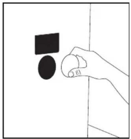
natural_image
Simple line drawing of a hand holding a circular object with a black square above it, against a plain background (no text or symbols)natural_image
Technical line drawing of a mechanical component with directional arrows indicating motion or flow (no text or symbols)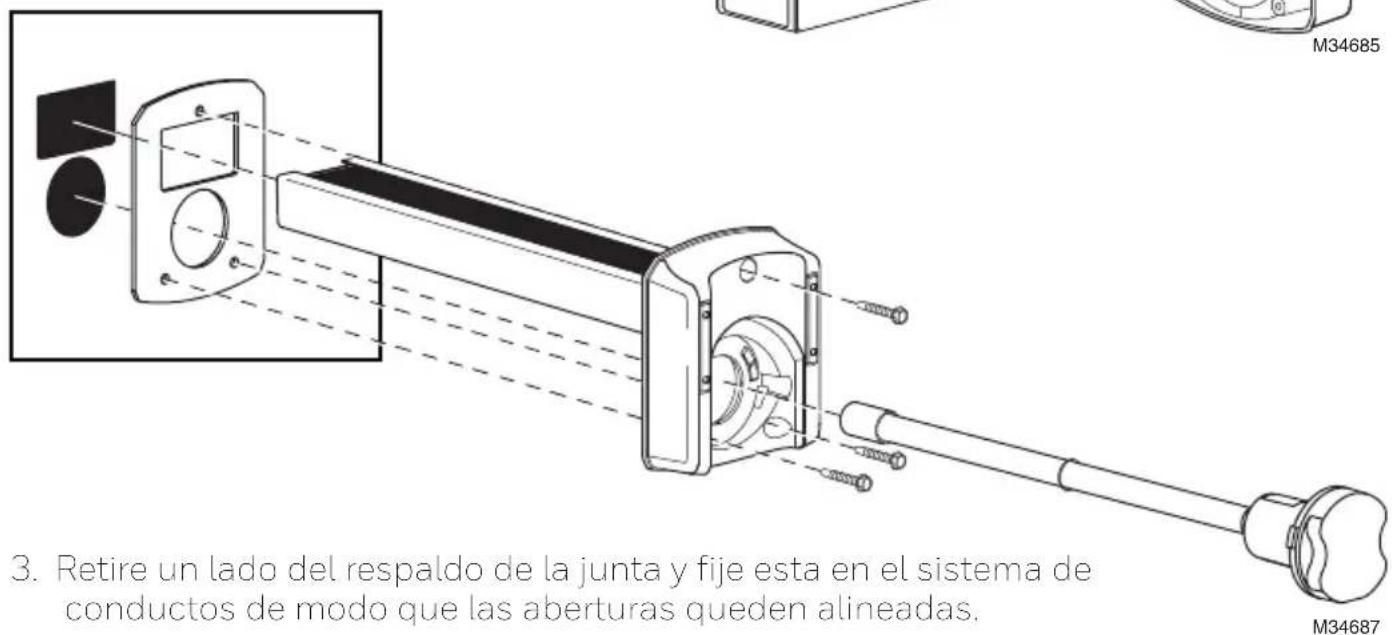
natural_image
Diagram of a device casing with rotating components and directional arrows (no text or symbols)natural_image
Line drawing of hands installing or adjusting a wall-mounted device (no text or symbols)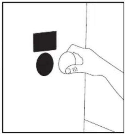
natural_image
Simple line drawing of a hand holding a small object near a wall, with no text or symbols present.natural_image
Technical line drawing of a mechanical assembly with directional arrows indicating motion (no text or symbols)natural_image
Two identical electronic device diagrams showing front and side views with internal components and directional arrows (no text or symbols)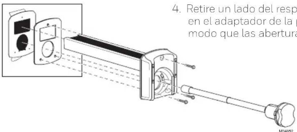
natural_image
Diagram of a mechanical or electrical component with circular features and directional arrows, no readable text or symbols.natural_image
Pure mechanical shaft diagram without any text, numbers, or symbolsnatural_image
Pure mechanical diagram showing a shaft connected to a connector with directional arrows, no text or symbols present.Reemplace la SnapLamp™ en la base
natural_image
Diagram of a device with circular components and bidirectional arrows indicating rotation (no text or symbols)Resideo Technologies Inc.
1985 Douglas Drive North, Golden Valley, MN 55422
1-800-468-1502
© 2020 Resideo Technologies, Inc. All rights reserved.
The Honeywell Home trademark is used under license from Honeywell International, Inc. This product is manufactured by Resideo Technologies, Inc. and its affiliates.
69-2796EFS-04

- Installation Instructions
- UV2400U Air Purifier
- Before Installing this Product
- WARNING: UV Light Hazard.
- Harmful to bare skin and eyes. Can cause temporary or permanent loss of vision. Never look at lamps while illuminated.
- CAUTION: Personal Injury Hazard. HVAC power supply can cause electrical shock.
- CAUTION: Breakable Glass Hazard. Can cause personal injury.
- CAUTION: Personal Injury Hazard. Power supply can cause electrical shock.
- CAUTION: UV Lamp Burn Hazard. Harmful to bare skin. Can cause severe burns.
- Parts Included
- Typical Mounting Locations
- Option 1
- IMPORTANT
- Option 2
- External Mounting for Metal Duct Applications
- Option 3
- Duct Board Mounting: For Duct Board Applications Only
- Power Supply Installation
- Power Supply Wiring
- WARNINGS:
- Maintenance
- Changing UV Lamp
- Replacing UV Lamp
- MERCURY NOTICE
- Broken Lamp Cleanup and Disposal
- Note: Use of replacement UV lamps other than Honeywell Home approved lamps voids warranty.
- Replacement Parts
- Five-Year Limited Warranty
- resideo
- Honeywell Home
- AVIS RELATIF AU MERCURE
Brand : HONEYWELL
Model : UV2400XBAL1/U
Category : Air purifier