AC1014 - Controller IFM - Free user manual and instructions
Find the device manual for free AC1014 IFM in PDF.
| Product type | AS-i DeviceNet Controller |
| Brand | IFM |
| Model | AC1014 |
| Number of AS-i masters | 1 or 2 |
| Network interface | DeviceNet (Group 2 Only Slave) |
| Supply voltage | 24 V DC (terminals +24 V and 0 V) |
| AS-i loop voltage | 30 V DC (terminals ASI+ and ASI-) |
| Protection | IP20 |
| Mounting | On 35 mm rail |
| Display | LED and 7-segment display (ALARM, CONFIG, etc.) |
| Operating modes | Cyclic polling, Bit strobe, Change of state, Cyclic |
| Main functions | Signal preprocessing, watchdog, gateway mode, configuration via explicit messages |
| Serial communication | RS232 for configuration (adjustable speed 4800 to 62400 baud) |
| DeviceNet addressing | Adjustable (default 063) |
| DeviceNet speed | Adjustable |
| AS-i slave capacity | Up to 31 per master |
| Data length | AS-i 1/2: 0..16 bytes; Preprocessing: 0..32 bytes |
| Diagnostics | Module/Network status LED (green/red flashing) |
| Safety | Power off before connection; ensure PE connection to ground |
| Maintenance and cleaning | No special maintenance; clean with a dry cloth |
Frequently Asked Questions - AC1014 IFM
User questions about AC1014 IFM
0 question about this device. Answer the ones you know or ask your own.
Ask a new question about this device
Download the instructions for your Controller in PDF format for free! Find your manual AC1014 - IFM and take your electronic device back in hand. On this page are published all the documents necessary for the use of your device. AC1014 by IFM.
USER MANUAL AC1014 IFM
Functions and features
- The AS-i DeviceNet controller integrates 1 or 2 AS-i masters, a mini controller and a group 2 Only DeviceNet slave interface to ODVA specification (Open DeviceNet Vendor Association)
- it controls the data exchange to the sensor/actuator level
- it processes the peripheral data in the integrated processor (signal preprocessing)
- it works as stand-alone controller with data exchange to the PC (visualisation)
- it is monitored by a watchdog
- it communicates with the higher-level control system (in the gateway mode)
- it supports the following operating modes according to the specifications: Cyclic polling, Bit strobe, Change of state and Cycle.
It is configured via explicit messages.
Mounting
Mount the controller onto a 35mm rail. The unit has protection IP20, therefore it should be mounted in a protected place (e.g. switching cabinet).
Electrical connection

Disconnect power. Connect the unit according to the terminal marking. Never connect the minus potentials to each other or the minus potentials and the PE connection.
Ensure an electrically safe ground connection between the AS-i controller (PE terminal) and the ground connection of the unit.
After application of the supply voltage all the LEDs and the LED display are switched on (LED test); then the version numbers of the hardware and the software are displayed for 1s each on the LED display.
Operating and display elements
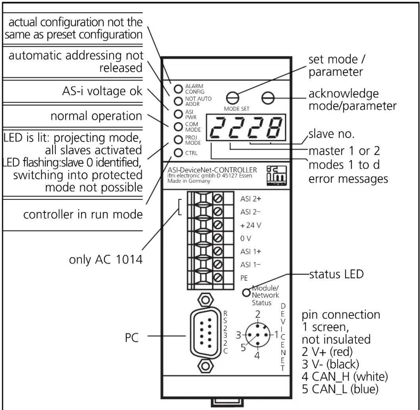
text_image
actual configuration not the same as preset configuration automatic addressing not released AS-i voltage ok normal operation LED is lit: projecting mode, all slaves activated LED flashing:slave 0 identified, switching into protected mode not possible controller in run mode only AC 1014 PC ALARM CONFIG NOT AUTO ADDR ASI PWR COM MODE PROJ MODE CTRL 2228 MODE SET set mode / parameter acknowledge mode/parameter slave no. master 1 or 2 modes 1 to d error messages ASI-DeviceNet-CONTROLLER ifm electronic gmbh-D 45127 Essen Made in Germany ASI 2+ ASI 2- +24 V 0 V ASI 1+ ASI 1- PE Module/ Network Status 2 3 4 DEVICE NET status LED pin connection 1 screen, not insulated 2 V+ (red) 3 V- (black) 4 CAN_H (white) 5 CAN_L (blue)Status LED|Colour Meaning
| Module/ Network Status | off | DeviceNet voltage not ok or MAC ID test not terminated |
| green flashing | controller is online, master allocation not ok | |
| green | controller is online, master allocation ok | |
| red flashing | time-out error during data transmission | |
| red | serious error: controller address allocated twice or bus-off status of the controller or faulty data telegram |
Diagnosis / adjustment
The AS-i controller is served via the higher-level host (PC). Some functions are accessible locally:
| Mode | Action Operating steps | |
| 1 | Store list of failed slaves see error messages | |
| 2 | Display detected slaves 0/1, 0/2, 2 - 4 | |
| 3 | Display projected slaves 0/1, 0/2, 2 - 4 | |
| 4 | Display activated slaves 0/1, 0/2, 2 - 4 | |
| 5 | Allocate address 0 to a slave 0/1, 0/2, 5 | |
| 6 | Allocate an address to slave 0 0/1, 0/2, 6 | |
| 7 | Auto addressing on / off | 0/1, 7 |
| 8 | Project slaves | 0/1, 0/2, 8 |
| 9 | Program processing run/stop | 0/1, 9 |
| A | Address controller | 0/1, A |
| b | Set transfer rate of the serial interface | 0/1, B |
| C | Set data lengths | 0/1, C |
| d | Set DeviceNet baud rate | 0/1, d |
| Locking/unlocking modes > 4 | locking/unlocking |
Assignment of the status nibbles:
| Bit no. | Meaning | = 1 | = 0 |
| 7 | signal preprocessing | running | stopped |
| 6 | AS-i power / configuration | not o.k. | o.k. |
| 5 | running up finished | yes | no |
| 4 | reserved |
0/1 Select mode
| 1 |  Mode Set Mode Set  Press several times until requested mode is displayed Press several times until requested mode is displayed |  Mode display flashing Mode display flashing | |
| 2 | Mode Set Acknowledgment of the requested mode | Display of the selected mode,display master 1 flashing |
0/2 Select master:
| 1 |  Mode SetAcknowledgment of master 1 Mode SetAcknowledgment of master 1 | 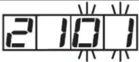 Display master 1,display of 1st slave flashing Display master 1,display of 1st slave flashing |
or:
| 1 |  Mode Set Press once Mode Set Press once | → |  Display of master 2 flashing Display of master 2 flashing |
| 2 |  Mode SetAcknowledgment of master 2 Mode SetAcknowledgment of master 2 | [HYX5] | 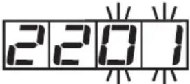 Display master 2,display of 1st slave flashing Display master 2,display of 1st slave flashing |
2/4 Display identified, projected and activated slaves
| 1 | Select mode and master (operating steps 0/1 and 0/2) | 2101Display master 1, display of 1st slave |
| 2 |  Mode Set Press several times Mode Set Press several times | → |  Display of other slaves Display of other slaves |
5 Allocate address 0 to a slave
| 1 | Select mode and master (operating steps 0/1 and 0/2) | 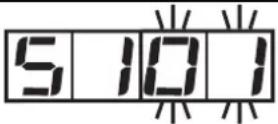 Display master, display of 1st slave flashing Display master, display of 1st slave flashing | |
| 2 | Mode SetPress several times until requested slave is displayed | 5 10 7Display of slave flashing (here slave 7) | |
| 3 | Mode SetPress once (= acknowledgment) | 5 10 7Address 0 is stored for selected slave |

Automatic addressing must be switched off (mode 7).
6 Allocate an address to slave 0
| 1 | Select mode and master (operating steps 0/1 and 0/2) | 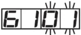 Display master,first free slave address flashing Display master,first free slave address flashing | |
| 2 |  Mode SetPress several times until requested address is displayed Mode SetPress several times until requested address is displayed | 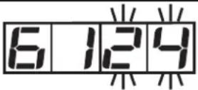 Display of selected address flashing (here address 24) Display of selected address flashing (here address 24) | |
| 3 |  Mode SetPress once (= acknowledgment) Mode SetPress once (= acknowledgment) |  New address for slave 0 is stored New address for slave 0 is stored |
7 Auto addressing on/off
= automatic addressing OFF
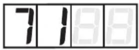
= simple automatic addressing ON (1 slave can be addressed automatically)
= multiple automatic addressing ON (several slaves can be addressed automatically)
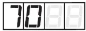
| 1 | Select mode (operating step 0/1) |  Display of preset value flashing Display of preset value flashing | |
| 2 | Mode SetPress several times until requested setting is displayed | 7 1 8 8 Display of newly selected setting flashing (here 1) | |
| 3 | Mode SetPress once (= acknowledgment) | 7 1 8 8 New setting is stored |
8 Project slaves
| 1 | Select mode and master (operating steps 0/1 and 0/2) |  Display master, display project mode flashing Display master, display project mode flashing | |
| 2 |  New configuration is stored New configuration is stored |
9 Program processing run/stop

= program processing running (RUN mode) (LED "CTRL" = on)

= program processing stopped (STOP mode) (LED "CTRL" = off)
| 1 | Select mode (operating step 0/1) | 9C - FDisplay of mode and preset value | |
| 2 |  Mode SetPress until requested setting is displayed Mode SetPress until requested setting is displayed |  Display of newly selected setting (here STOP) Display of newly selected setting (here STOP) | |
| 3 | Mode SetPress once (= acknowledgment) | 9C - SNew setting is stored |
A Address controller (default address = 063)
| 1 | Select mode (operating step 0/1) |  Display of preset address flashing Display of preset address flashing | |
| 2 |  Mode SetPress several times until requested address is displayed Mode SetPress several times until requested address is displayed | A004Display of new address flashing (here 004) | |
| 3 | Mode SetPress once (= acknowledgment) | A004New address is stored |
The address is only valid for the RS232 interface.
b Set transfer rate of the serial interface
| 1 | Select mode(operating step 0/1) |  | 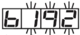 Display of preset value flashing Display of preset value flashing |
| 2 |   Mode SetPress several times until requested setting is displayed Mode SetPress several times until requested setting is displayed |  |  Display of newly selected setting flashing (here 96) Display of newly selected setting flashing (here 96) |
| 3 | Mode SetPress once (= acknowledgment) | New setting is stored |
Possible settings:b_48 (= 4800 baud), b_96 (= 9600 baud), b192 (= 19200 baud = default), b384 (=38400 baud), b576 (= 57600 baud), b624 (= 62400 baud).
C Set data lengths for the DeviceNet coupling
| 1 | Select mode(operating step 0/1) | 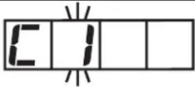 Display of preset value flashing Display of preset value flashing | |
| 2 | Mode SetPress several times until requested setting is displayed | Display of newly selected setting flashing | |
| 3 | Mode SetPress once | Display of set data length | |
| 4 | Mode SetPress several times until requested setting is displayed | Display of newly selected setting flashing | |
| 5 | Mode SetPress once (= acknowledgment) | New setting is stored |
Possible settings:
C1 = AS-i 1:0 ... 16 bytes data length in steps of 1 byte
C2 = AS-i 2: 0 ... 16 bytes data length
CC = signal preprocessing: 0,4,8,12,16,24,28 or 32 bytes data length
Setting in the factory (corresponds to the Gateway mode)
C1 = 16
C2 = 16
CC = 00

Disconnect the controller once to activate the changed data or confirm the controller address A once again.
d Set the DeviceNet baud rate
| 1 | Select mode (operating step 0/1) | 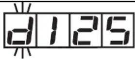 Display of preset value flashing Display of preset value flashing | |
| 2 |  Mode SetPress once Mode SetPress once | 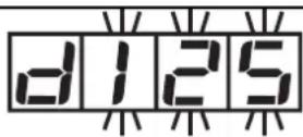 Display of the baud rate Display of the baud rate | |
| 3 |  Mode SetPress several times until requested setting is displayed Mode SetPress several times until requested setting is displayed |  Display of newly selected setting flashing Display of newly selected setting flashing | |
| 4 |  Mode SetPress once (= acknowledgment) Mode SetPress once (= acknowledgment) | 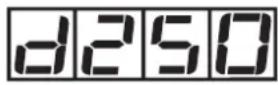 New setting is stored New setting is stored |
Locking/unlocking modes > 4
| 1 | Select mode (operating step 0/1) |  Display of the selected mode Display of the selected mode | |
| 2 |  Mode Set Press twice Mode Set Press twice |  Display of locking flashing Display of locking flashing | |
| 3 |  Mode Set Press once (= acknowledgment) Mode Set Press once (= acknowledgment) |  Display locking active Display locking active |
Unlocking: Press both buttons for approx. 5s; as acknowledgment digit 1 is flashing in the LED display.
Error messages

Display of missing/defective slaves
(digit 2 = master; digits 3 and 4 = slave no.); the slaves are displayed at intervals of seconds.
The list of failed slaves can be stored until the slaves have been replaced.
- Press the SET button twice (for the list of master 1) or SET -MODE - SET (for the list of master 2). The lowest address of the error list is displayed flashing.
- Replace the failed slave by a slave with the same configuration and with the address 0; it will receive the indicated address; (the function “automatic addressing” must be activated). If other addresses are displayed, proceed in the same way until the list has been completed.
- The function will be ended when the slaves have been replaced or the SET button has been pressed.

Bus error: field bus (DeviceNet) not active or not connected

Software version AS-i string 1 ≠AS-i string 2

Error during initialisation of the Profibus interface module

AS-i master 2: operating mode already active

AS-i master 2: addressing mode already active

AS-i master 2: error during the setting of the new address

AS-i master 2: error during the deletion of the old address

AS-i master 2: slave with old address does not exist

AS-i master 2: slave with new address exists

AS-i master 2 offline/slave 0 exists

AS-i master 2 not in the projecting mode

AS-i master 2 not in the projecting mode

AS-i master 2 not in the projecting mode/ configuration data not valid

AS-i master 2 not in the projecting mode

AS-i master 2: offline

AS-i master 2: parameter value invalid

AS-i master 1: operating mode already active

AS-i master 1: addressing mode already active

AS-i master 1: error during the setting of the new address
 | AS-i master 1: error during the deletion of the old address |
 | AS-i master 1: slave with old address does not exist |
 | AS-i master 1: slave with new address exists |
 | AS-i master 1 offline/slave 0 exists |
 | AS-i master 1 not in the projecting mode |
 | AS-i master 1 not in the projecting mode |
 | AS-i master 1 not in the projecting mode/ configuration data not valid |
 | AS-i master 1 not in the projecting mode |
 | AS-i master 1 offline |
 | AS-i master 1: parameter value invalid |
 | Master 2 does not exist |
 | No plc program loaded |
 | No entry in LDS (list of detected slaves) |
 | No entry in LPS (list of projected slaves) |
 | No entry in LAS (list of activated slaves) |
 | No free slave address available |
 | Key handling disabled |
 | Function only possible in the projecting mode |
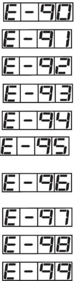
text_image
E - 90 E - 91 E - 92 E - 93 E - 94 E - 95 E - 96 E - 97 E - 98 E - 99Slave 0 does not exist
Target address already allotted
New address could not be allotted
Multiple automatic addressing not active
I/O configuration ≠projected configuration
Incorrect ID code (does not correspond to projected value)
Addressing not possible since "automatic addressing" has not been activated
Addressing not possible, slaves are missing
Protected operating mode is not active
Slave 0 already exists
Controllers with one master (AC1008)
Input Rating
24V DC 80mA
Output Rating
± 3V DC
Electrical ratings
Controllers with two masters (AC1014)
Input Rating
24V DC 80mA
Output Rating
± 2 × 3V DC