
CR7032 - Controller IFM - Free user manual and instructions
Find the device manual for free CR7032 IFM in PDF.


| Product Type | Programmable Safety Controller for mobile machinery |
| Model | CR7032 (SafetyController) |
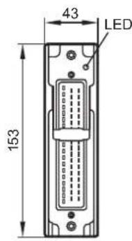
| Dimensions (H x W x D) | 153 x 226 x 43 mm |
| Weight | 1.2 kg |
| Operating Voltage | 8...32 V DC (12/24 V battery system) |
| Inputs | 16 configurable: digital, analogue (0-10 V, 0-20 mA, ratiometric), frequency (≤30 kHz) |
| Outputs | 16 configurable: digital high-side/low-side, PWM, current-controlled, H-bridge |
| Interfaces | 2 x CAN (CANopen/SAE J1939), RS-232, USB (virtual COM port) |
| Programming | CODESYS 2.3 (IEC 61131-3) via USB or RS-232 |
| Safety Level | EN ISO 13849-1:2008 Category 3 PL d; IEC 62061:2005 SIL CL 2 |
| Protection Rating | IP67 (with sealed connector) |
| Environmental Temperature | Operating: -40 to 75 °C; Storage: -40 to 85 °C |
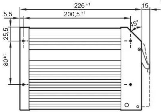
| Mounting | Screw fixing with 4 M5 screws; horizontal or vertical orientation |
| Electrical Connection | 1 x 55-pin connector (AMP/Framatome), crimp 0.5-2.5 mm² |
| Maintenance | Maintenance-free; do not open; repair by manufacturer only |
| Disposal | Dispose according to national environmental regulations |
| Processor | 32-bit Infineon TriCore 1796 |
| Memory | Flash: 4 MB; RAM: 2 MB; Remanent: 128 KB |
| Certifications | CE, EC declaration of conformity at www.ifm.com |
Frequently Asked Questions - CR7032 IFM
User questions about CR7032 IFM
0 question about this device. Answer the ones you know or ask your own.
Ask a new question about this device
Download the instructions for your Controller in PDF format for free! Find your manual CR7032 - IFM and take your electronic device back in hand. On this page are published all the documents necessary for the use of your device. CR7032 by IFM.
USER MANUAL CR7032 IFM
Original operating instructions SafetyController
CR7032
UK
natural_image
Pure technical line drawing of a rectangular panel with horizontal lines and mounting holes, no text or symbols present.Functions and features
The programmable controllers of the series "SafetyController" are designed for use in safety-related applications. They are suitable for direct installation in vehicles and mobile machines using the on-board system (12/24 V DC battery operation).
Special hardware and software functions are integrated into the controllers for safety-related applications, as described in these instructions. This enables the use as a safety controller.
WARNING
The "SafetyController" devices are approved for safety-related tasks in the field of operator protection, if the corresponding system check routines are integrated in the operating system and the application software and have been checked by a complete function test. However, the final classification and approval of a system (hardware and software) may only be carried out by the corresponding supervisory organisations.
Programming and important additions to these instructions
In addition to the programming system CODESYS and the software tool "Downloader", the following documents are required for programming and commissioning of the controller:
- "Important notes on CR7n32" for the software versions used by you
- System manual "SafetyController"
- Programming manual "CODESYS"
If you do not have these documents, you can request them in German or English free of charge on the indicated website or via e-mail, fax, phone or post at the address stated below.
| Internet www.ifm.com/uk | |
| Address ifm electronic Ltd. efector House • Kingsway Business Park • Oldfield RoadHampton • Middlesex TW12 2HD | |
| enquiry_gb@ifm.com | |
| Fax 020 8213-0001 | |
| Telephone 020 8213-0000 | |
Set-up
Only qualified staff is allowed to set up the device.
Furthermore we expressly point out that any liability is excluded if the notes in the programming and set-up documents are not adhered to.
1 Preliminary note 4
1.1 Symbols used.... 4
1.2 Warning signs used 4
2 Safety instructions 5
2.1 General....5
2.2 Target group 5
2.3 Electrical connection 5
2.4 Housing temperature 5
2.5 Tampering with the device 5
2.6 Electromagnetic compatibility.... 5
2.7 Electrical welding on vehicles and plants 5
3 Functions and features 6
4 Installation....7
4.1 Fixing 7
4.2 Installation position. 7
4.3 Mounting surface 8
4.4 Heat dissipation 8
5 Electrical connection....9
5.1 Wiring 9
5.2 Ground connection 9
5.3 Fuses 9
5.4 Laying the supply and signal cables.... 10
5.5 Frequency and analogue inputs 10
5.6 Supply low-side digital outputs (B_L) 11
5.7 Connection technology....11
5.8 USB interface 12
5.8.1 Hardware requirement 12
5.8.2 Short-circuit protection 12
6 Set-up.... 13
6.1 Interfaces and system requirements 13
6.2 Programming via USB interface 13
6.2.1 Install the USB drivers 13
6.2.2 Install and define the virtual COM port. 16
6.3 Uninstall the drivers 17
7 Technical data.... 18
7.1 Mechanical and electric data 18
7.2 Test standards and regulations 20
7.3 Input characteristics 21
7.4 Output characteristics.... 22
7.5 Wiring 23
8 Maintenance, repair and disposal. 24
9 Approvals/standards.... 24

This document is the original instructions.
Licences and trademarks
All trademarks and company names are subject to the copyright of the respective companies.
1 Preliminary note
This document applies to devices of the type "SafetyController" (art. no.: CR7032). These instructions are part of the device.
This document is intended for specialists. These specialists are people who are qualified by their appropriate training and their experience to see risks and to avoid possible hazards that may be caused during operation or maintenance of the device. The document contains information about the correct handling of the device.
Read this document before use to familiarise yourself with operating conditions, installation and operation. Keep this document during the entire duration of use of the device.
Adhere to the safety instructions.
1.1 Symbols used
▶ Instructions
Reaction, result
[...] Designation of keys, buttons or indications
→ Cross-reference

Important note
Non-compliance can result in malfunction or interference.

Information
Supplementary note
1.2 Warning signs used
WARNING
Warning of serious personal injury.
Death or serious irreversible injuries may result.
CAUTION
Warning of personal injury.
Slight reversible injuries may result.
NOTE
Warning of damage to property.
2 Safety instructions
2.1 General
These instructions are part of the device. They contain information and illustrations about the correct handling of the device and must be read before installation or use.
Observe the operating instructions. Non-observance of the instructions, operation which is not in accordance with use as prescribed below, wrong installation or incorrect handling can seriously affect the safety of operators and machinery.
2.2 Target group
These instructions are intended for authorised persons according to the EMC and low-voltage directives. The unit must be installed, connected and put into operation by a qualified electrician trained in safety technology.
2.3 Electrical connection
The device is designed for supply via a mobile on-board system (12/24 V DC battery operation).
Disconnect the unit externally before handling it. If necessary, also disconnect any independently supplied output load circuits.
The connection terminals may only be supplied with the signals indicated in the technical data and/or on the device label and only the approved accessories of ifm electronic may be connected.
2.4 Housing temperature
As described in the technical specifications below the device can be operated in a wide ambient temperature range. Because of the additional internal heating the housing walls can have high perceptible temperatures when touched in hot environments.
2.5 Tampering with the device
In case of malfunctions or uncertainties please contact the manufacturer. Any tampering with the device can seriously affect the safety of operators and machinery. This is not permitted and leads to the exclusion of any liability and warranty claims.
2.6 Electromagnetic compatibility
This is a class A product. It can cause radio interference in domestic areas. In this case the operator is requested to take appropriate measures.
2.7 Electrical welding on vehicles and plants
Welding work on the chassis frame must only be carried out by qualified persons.
Remove and cover the plus and minus terminals of the batteries.
Disconnect all contacts of the controller from the on-board system prior to welding on the vehicle or plant. Connect the earth terminal of the welding device directly to the part to be welded.
Do not touch the controller or electric cables with the welding electrode or the earth terminal of the welding device.
Protect the controller against weld slag.
3 Functions and features
The freely programmable controllers of the "SafetyController" series are rated for use under difficult conditions (e.g. extended temperature range, strong vibration, intensive EMC interference).
▶ Observe the operating conditions ( 7.2 Test standards and regulations).

WARNING
Observe the introduction ( pages II ff)!
- Functions and features
- Programming and important additions to these instructions
- Set-up
4 Installation
4.1 Fixing
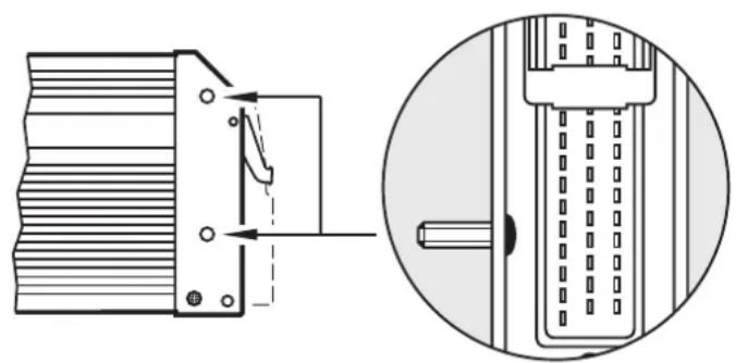
▶ Fix the controller to a flat surface using 4 M5 screws.
Screw material: steel or stainless steel
Tightening torque: 8 ±2 Nm
NOTE
Use screws with a low head to avoid that the connector is damaged when placed and locked.
| Screws to be used (examples) Standard | |
| Button head hexagon socket screws (M5 x L) ISO 7380 | |
| Cylinder screws with hexagon socket and low head (M5 x L) DIN 7984 | |
| Cutting screws for metric ISO thread with low head DIN 7500 |
natural_image
Technical diagram showing a mechanical component with internal structure and its cross-sectional view (no text or symbols)Example button head hexagon socket screw
4.2 Installation position
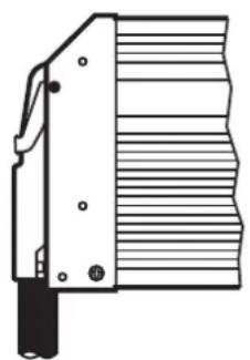
▶ Align the controller so that the cable entries of the connectors face downwards.
natural_image
Technical line drawing of a mechanical component with grooves and a handle (no text or symbols)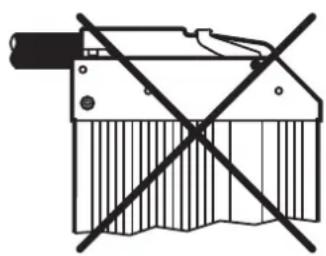
natural_image
Pure mechanical component diagram without any text, numbers, or symbols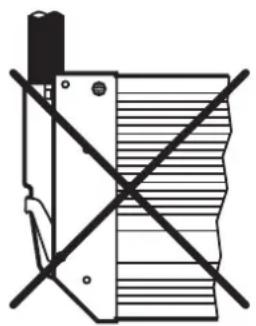
natural_image
Pure electrical circuit lines without any symbolsPreferred installation position
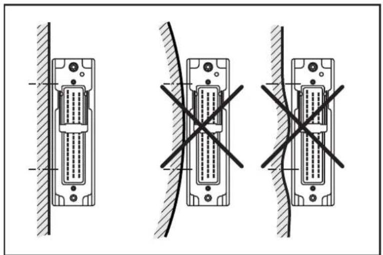
4.3 Mounting surface
NOTE
The housing must not be exposed to any torsional forces or mechanical stress.
▶ Use compensating elements if there is no flat mounting surface available.
natural_image
Three technical diagrams showing a connector with labeled pins and cross-sectional views, no text or symbols present.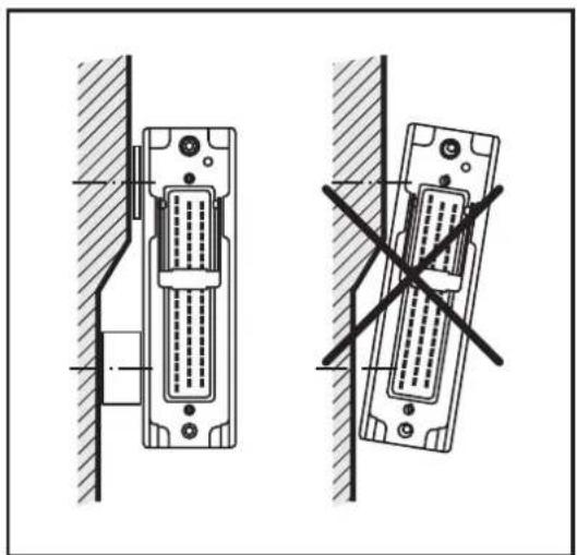
natural_image
Technical line drawing of two identical electronic connectors with a diagonal cross mark indicating a gap (no text or symbols present)Mounting surface
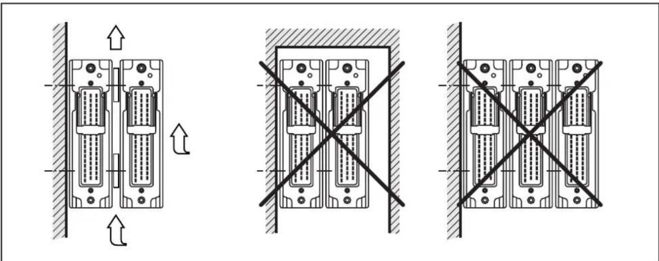
4.4 Heat dissipation
▶ Ensure sufficient heat dissipation as the internal heating of the electronics is conducted away via the housing.
In case of sandwich mounting of controllers use spacers.
natural_image
Three schematic diagrams of electronic device modules with directional arrows indicating movement, no text or symbols present.Heat dissipation and sandwich mounting
5 Electrical connection
5.1 Wiring
Wiring ( 7 Technical data)

Only connect the connector pins as shown in the pin layout. Unspecified connector pins remain unconnected.
▶ Connect all indicated supply cables and GND terminals.
5.2 Ground connection
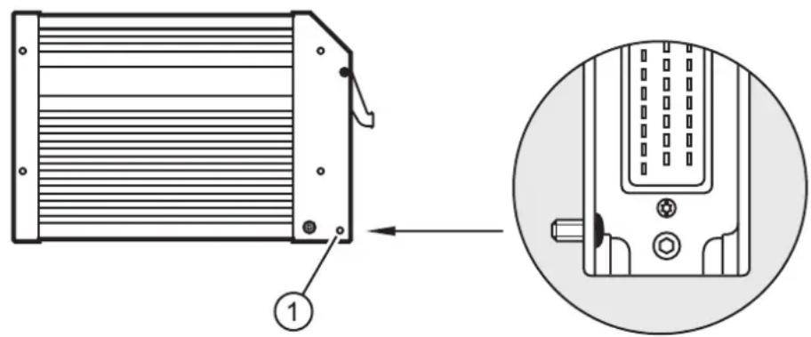
1: Drill hole for ground connection

To ensure the protection of the device against electrical interference and the safe function of the device, the housing must be connected to the ground of the vehicle.
▶ Establish a connection between the device and the ground of the vehicle using M5 screws.
Screws to be used ( 4.1 Fixing)
5.3 Fuses
▶ The individual electric circuits must be protected in order to protect the whole system.
| Potential Description Pin no. Fuse | |||
| VBB_s | Supply voltage sensors/module 10 ≤ 2 A time-lag | ||
| VBB_o | Supply voltage outputs 19 ≤ 15 A | ||
| VBB_R | Supply voltage via relay 01 ≤ 15 A | ||
5.4 Laying the supply and signal cables
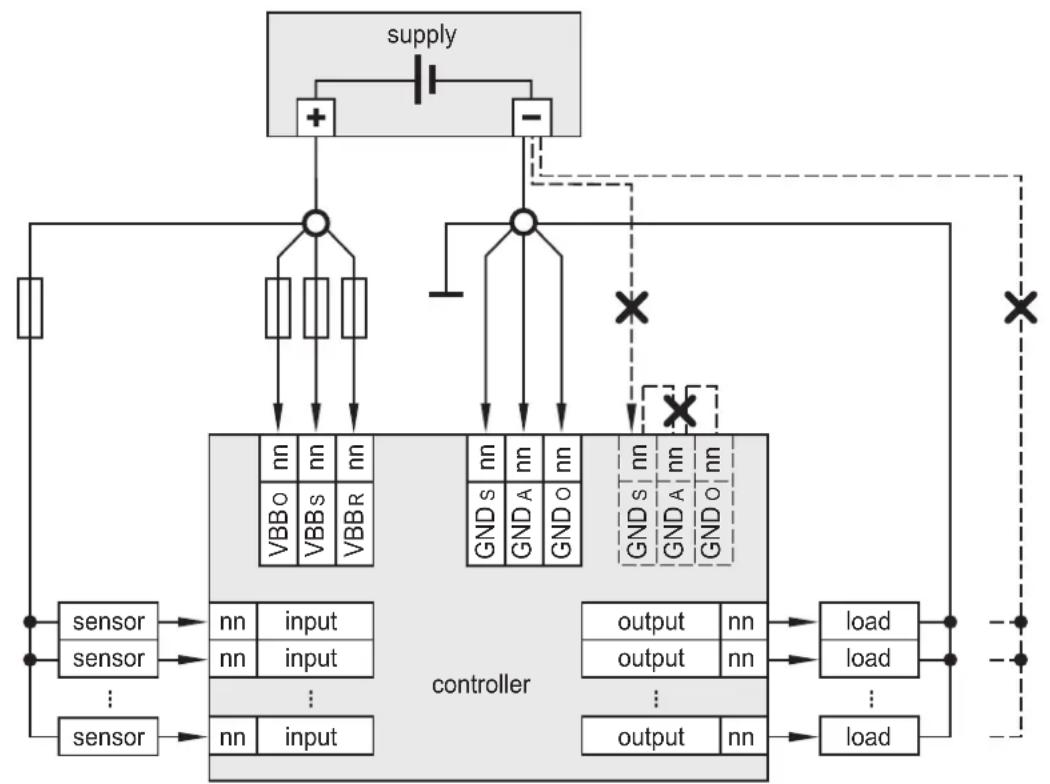
flowchart
graph TD
    A["supply"] --> B["+"]
    A --> C["-"]
    B --> D["controller"]
    C --> D
    D --> E["sensor"]
    D --> F["sensor"]
    D --> G["..."]
    D --> H["sensor"]
    E --> I["nn input"]
    F --> J["nn input"]
    G --> K["..."]
    H --> L["nn input"]
    I --> M["output nn"]
    J --> N["output nn"]
    K --> O["output nn"]
    L --> P["load"]
    M --> Q["load"]
    N --> R["load"]
    O --> S["..."]
    P --> T["..."]
    Q --> U["..."]
    R --> V["..."]
    S --> W["..."]
    T --> X["..."]
    U --> Y["..."]
    V --> Z["..."]
    W --> AA["..."]
    X --> AB["..."]
    Y --> AC["..."]
X = not permissible

WARNING
The linking of connections in the plug is not permitted and can affect the safety of operators and machinery.
▶ Basically all supply and signal cables must be laid separately.
▶ Connect supply and ground cables to the controller and to the sensors/ actuators via the respective common star point.

If a prewired connection cable is used, remove the cores with unused signal inputs and outputs.
Unused cores, in particular core loops, lead to interference coupling that can influence the connected controller.
5.5 Frequency and analogue inputs
▶ Operate frequency inputs with screened cables, so that useful signals are not affected by external interference.
▶ Connect screens to ground on one side.
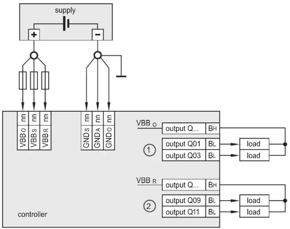
5.6 Supply low-side digital outputs ( B_L )
flowchart
graph TD
    A["supply"] --> B["+"]
    A --> C["-"]
    B --> D["VBBo"]
    B --> E["VBBs"]
    B --> F["VBBR"]
    C --> G["VBBo"]
    C --> H["VBBs"]
    C --> I["VBBR"]
    D --> J["controller"]
    E --> J
    F --> J
    G --> K["GNDs"]
    G --> L["GNDA"]
    G --> M["GNDo"]
    K --> N["VBBo"]
    L --> O["GNDa"]
    M --> P["GNDo"]
    N --> Q["output Q... BH"]
    O --> R["output Q01 BL"]
    O --> S["output Q03 BL"]
    Q --> T["load"]
    R --> U["load"]
    S --> V["load"]
    W["VBBo"] --> X["VBBo"]
    Y["VBBs"] --> Z["VBBs"]
    AA["VBBR"] --> AB["VBBR"]
    AC["VBBo"] --> AD["VBBo"]
    AE["VBBs"] --> AF["VBBs"]
    AG["VBBR"] --> AH["VBBR"]
    AI["VBBo"] --> AJ["controller"]
    AK["VBBs"] --> AL["controller"]
    AM["VBBR"] --> AN["controller"]
    AO["VBBo"] --> AP["controller"]
    AQ["VBBs"] --> AR["controller"]
    AS["VBBR"] --> AT["controller"]
    AU["VBBo"] --> AV["controller"]
    AW["VBBs"] --> AX["controller"]
    AY["VBBR"] --> AZ["controller"]
Supply low-side digital outputs ( B_L )
1: Outputs of the output group VBB 0
2: Outputs of the output group VBBR
▶ Supply low-side outputs (Ba a high-side output ( B_H ) of the same output group.
5.7 Connection technology
NOTE
Only connect the 55-pole connectors when the supply voltage is disconnected. No "hot plugging" is permitted.
5.8 USB interface
5.8.1 Hardware requirement
The USB controller used is USB 2.0 compatible. The USB interface is provided as a virtual COM port under Windows ( 6.2 Programming via USB interface).
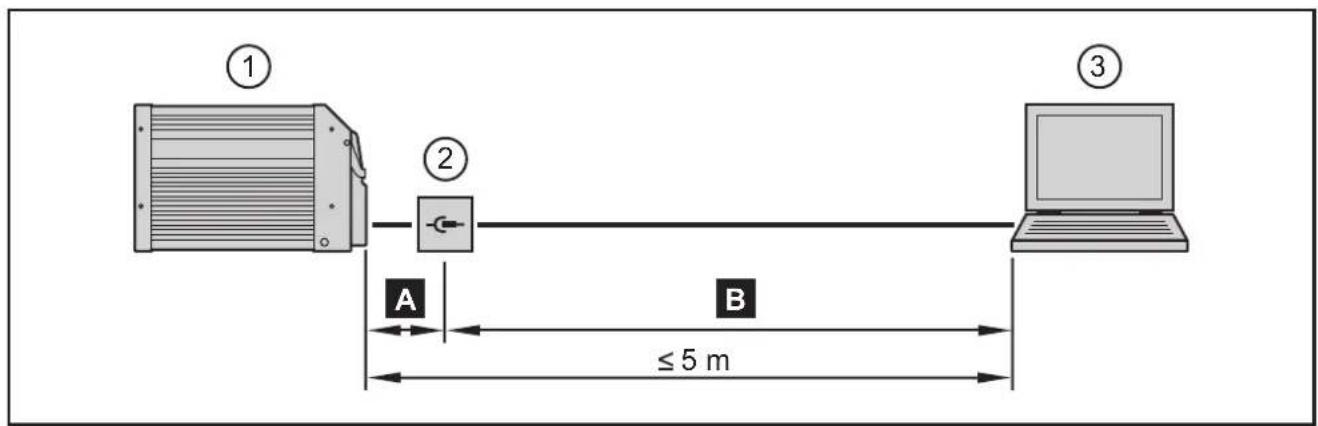
- Controller (55-pin connector)
- USB connector for programming and service purposes
- Notebook/PC
A Connection controller to USB connector, permanent ( ≤ 3 m).
▶ Position the USB connector in immediate vicinity to the controller. The cable length "A" considerably influences the quality of the USB data transmission.
B Connection USB connector to notebook / PC, temporary
▶ Use a connection cable with the designation "Full Speed/High Speed" (= USB connection cable with twisted and screened cores).
▶ Do not make a connection using several USB connection cables.
▶ Remove the connection cable after the programming or service works.
5.8.2 Short-circuit protection
NOTE
The USB interface is not protected against short circuits with a live wire outside the following voltage ranges:
USB P:-0.5...3.8 V DC
USB N:-0.5...3.8 V DC
USB_5V:-0.5...10.0 V DC
A short circuit will destruct the USB interface.
6 Set-up

WARNING
Observe the introduction ( pages II ff)!
- Functions and features
- Programming and important additions to these instructions
- Set-up
6.1 Interfaces and system requirements
The user can easily create the application program by means of the IEC 61131-3 compliant CODESYS programming system.
The "Downloader" software tool is used for the download to the controller. This tool ensures error-free data transfer via redundancy check (CRC).

System requirements for RS-232 and CAN1-4:
Microsoft Windows XP, SP1/2 or higher
System requirements for USB (virtual COM port):
Windows XP, SP2 or higher
6.2 Programming via USB interface

Note in general:
- The controller can be connected to any USB interface. The number of the COM port does not change.
- Only connect one controller for programming to the PC.
- Special USB and COM port drivers are required.
6.2.1 Install the USB drivers
These drivers provide a "virtual COM port", i.e. another artificial serial interface, on the PC.
The drivers can be found on the ifm ecomat mobile CD.

Changes to the system settings of the PC require extended user rights.
Contact your system administrator.

The following descriptions point out the installation under Windows XP. In other Windows versions there may be different menu names or structures.
▶ Connect the controller to the PC via the USB interface.
When started for the first time, the Windows dialogue box "Found New Hardware Wizard" automatically appears.
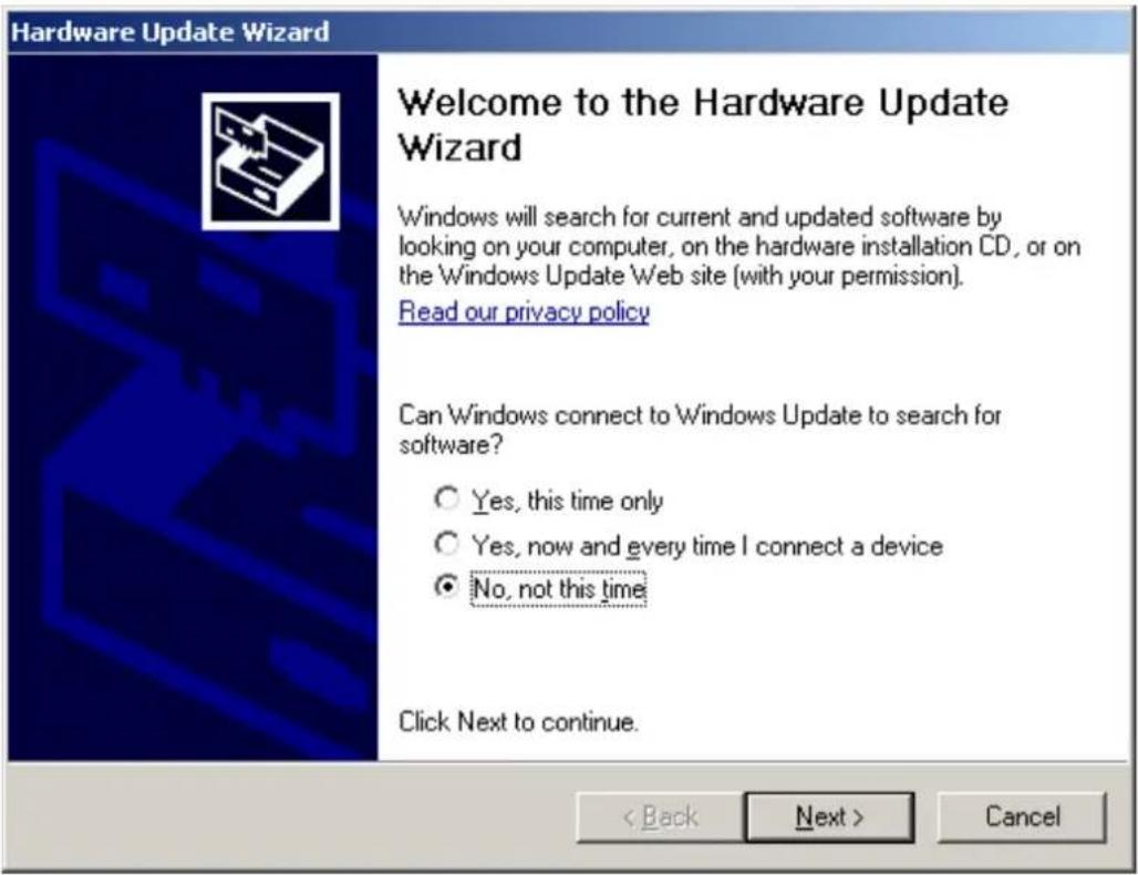
▶ Select [No, not this time].
(Prevents the automatic search for a new Windows update)
▶ Click on [Next] to continue.
natural_image
Abstract blue background with diagonal light streaks (no text or symbols)What do you want the wizard to do?
○ Install the software automatically (Recommended)
Install from a list or specific location (Advanced)
Click Next to continue.
< Back
Next>
Cancel
▶ Select [Install from a list or specific location].
(Enables the targeted search and selection of the required driver)
▶ Click on [Next] to continue.
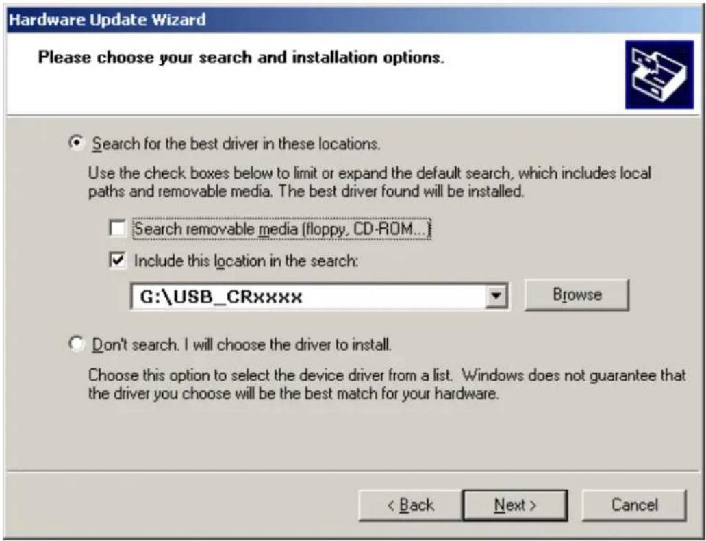
In case of installation using the ecomat mobile CD, select "Include this location in the search" → Drive letter:\USB_CRxxxx.
If the USB driver is located in a hard disk directory (e.g. after an internet download), select the directory using the browser function in the dialogue window. Alternatively, enter the storage location directly.

Only if the Windows installation wizard has found a valid driver file can you change to the next dialogue box with [Next].

Windows carries out a "Windows logo test".
The result of the system-internal test does not have any effect on the function of the software.
▶ Acknowledge the possible message "Windows logo test not passed" with [Continue].
The selected driver is displayed.
A message appears that installation was carried out correctly.
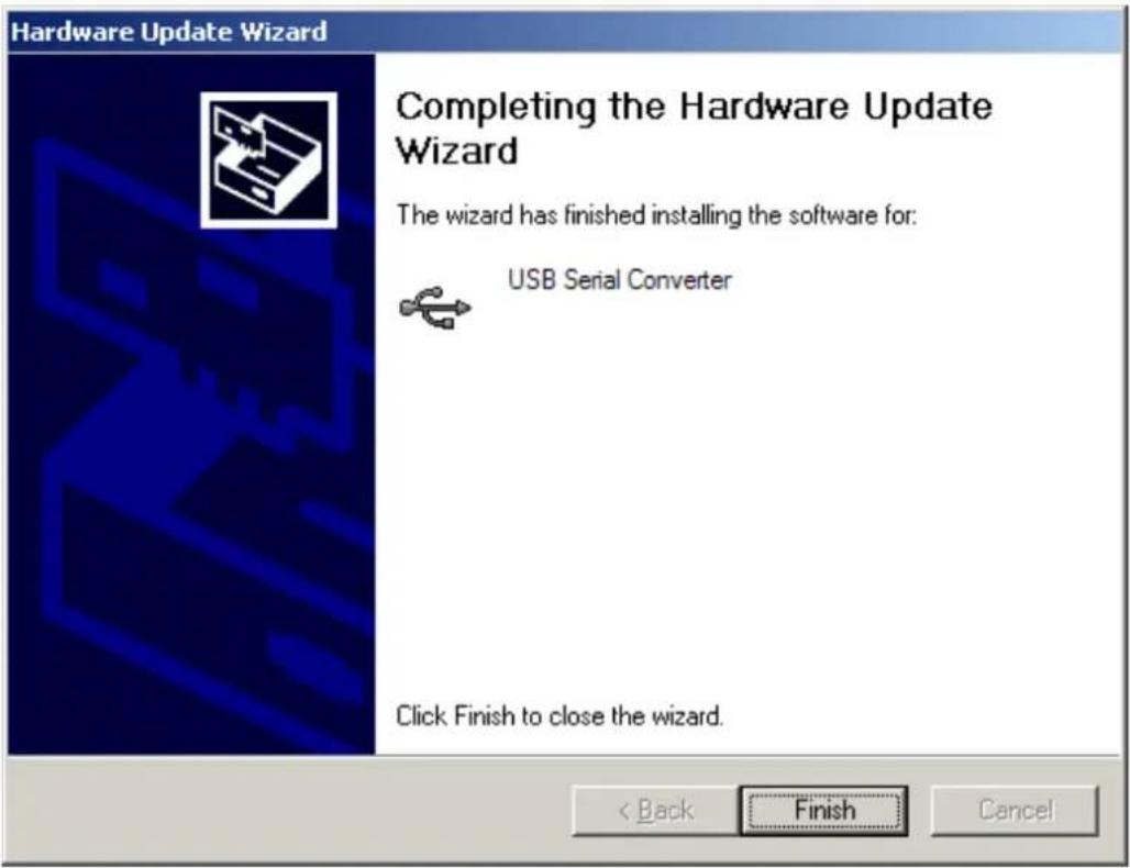
▶ Complete the installation with [Finish].
6.2.2 Install and define the virtual COM port
The installation is only necessary when started for the first time. The installation procedure is identical to the previous USB driver installation ( 6.2.1).
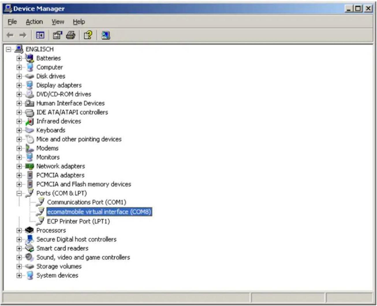
The installation program automatically selects the next free COM port (e.g. COM3) for the driver.
In case of conflicts with other programs, change the setting for the COM port in the Windows device manager.
- Open the device manager. The service program device manager can for example be accessed via Start → Control Panel → Device Manager.
- Select the entry with a double click in the directory "Ports (COM & LPT)". As an alternative: Right mouse click → Properties.
- Click on [Port settings] in the following dialogue box.
- Select [Advanced...] and redefine the COM port in the "Advanced Settings" menu (e.g. COM8), if necessary.

Do not use a COM port which is already used by another device. In most computers COM1 and COM2 are already assigned by the hardware interfaces.
▶ Confirm the setting with [OK].
The new COM port is indicated in the device manager following the driver name.
6.3 Uninstall the drivers

If a driver is to be updated, the installed drivers have to be deinstalled first of all.
▶ Disconnect the USB connection between the controller and the PC.
▶ Open the service program "Software" via the start menu → Control Panel.
▶ Uninstall the drivers successively with [Change/Remove].
7 Technical data
7.1 Mechanical and electric data
CR7032
SafetyController
EN ISO 13849-1:2008 Category 3 PL d
IEC 62061:2005 SIL CL 2
32-bit processor
16 inputs / 16 outputs
2 CANsafety interfaces
CODESYS 2.3
8...32 V DC
CE

Technical data
Mechanical data
Housing
Dimensions (H x W x D)
Installation
Connection
Weight
Housing/storage temperature
Protection rating
Electrical data
Input/output channels
Inputs
Outputs
Operating voltage
Overvoltage
Input voltage gradient
Reverse polarity protection
Current consumption
CAN interfaces 1...4
Baud rate
Communication profile
Serial interface
Baud rate
Topology
Protocol
Virtual COM port
Processor
Controller as black-box system
to implement a central or decentralised system design
| Closed, screened metal housing with flange fastening |
| 153 x 226 x 43 mm |
| Screw connection by means of 4 M5 x L screws to DIN 7500 or DIN 7984Mounting position horizontal or vertical to the mounting wall |
| 1 55-pin connector, latched, protected against reverse polarity, type AMP or Framatome AMP junior timer contacts, crimp connection 0.5/2.5 mm^2 |
| 1.2 kg |
| -40...75 °C (depending on the load) / -40...85 °C |
| IP 67 (for inserted connector with individually sealed cores, e.g. EC2084) |
| 32 (16 inputs / 16 outputs) |
| Configurable, safety-relatedDigital for positive/negative sensor signals, positive with diagnostic capabilitiesAnalogue (0...10/32 V, 0...20 mA, ratiometric)Frequency (≤ 30 kHz) |
| Configurable, safety-relatedDigital positive/negative switching (high/low side)PWM output (20...250 Hz, 8 x max. 4 A, 8 x max. 2 A)Current-controlled (8 x 0.01...2 A, 8 x 0.02...4 A) |
| 8...32 V DC36 V for t ≤ 10 s>1.3 V/s |
| Yes |
| ≤ 160 mA (without external load at 24 V DC) |
| CAN interface 2.0 A/B, ISO 1189850 Kbits/s...1 Mbit/s (default 125 Kbits/s)CANopen, CiA DS 301 version 4, CiA DS 401 version 1.4or SAE J 1939 or free protocolor 2 x CANsafety for safe data transmission |
| RS-232 C9.6...115.2 Kbit/s (default 115.2 Kbits/s)Point-to-point (max. 2 participants); master-slave connectionPredefined ifm protocol (INTELHEX) |
| USB, max. 1 MBaud |
| 32-bit CPU Infineon TriCore 1796 |
CR7032 Technical data
| Device monitoring Undervoltage/overvoltage monitoring | |
| Watchdog function(extended safety monitoring according to IEC 62061 and ISO 13849)Checksum test for program and systemExcess temperature monitoring | |
| Process monitoring concept Second switch-off mode for 8 outputs each via a relay(according to IEC 62061 and ISO 13849) | |
| Physical memory Flash: 4 Mbytes | RAM: 2 MbytesRemanent memory: 128 Kbytes |
| Memory allocation See system manual | www.ifm.com → Data sheet search → CR7032 → More information |
| Software/programming | |
| Programming system CODESYS version | 2.3 (IEC 61131-3) |
| Display elements | |
| Status indication Three-colour LED (R/G,B) | |
Operating states
No longer valid if the colours and/or fl ashing modes are changed by the application program.
| LED colour Status Description | ||
| - Off No operating voltage | ||
| Yellow | 1 x on | Initialisation or reset checks |
| Green | 5 Hz | No operating system loaded |
| 2.0 Hz | Run | |
| On | Stop | |
| Red | 2.0 Hz | Run with error |
| on | Fatal error or stop with error | |
7.2 Test standards and regulations
| CR7032 Technical data | |||
| Safety-related characteristics | |||
| According to IEC 62061:2005 | Safety Integrity Level Claim Limit SIL CL 2 | ||
| Probability of Dangerous Failure per Hour PFH | o | 1.227 × 10^-7 | |
| According to ISO 13849-1:2008 | Performance Level PL d | ||
| Test standards and regulations | |||
| Electrical tests EN 61000-6-2: 2005 Electromagnetic compatibility (EMC) Immunity | |||
ifm electronic gmbh • Friedrichstraße 1 • 45128 Essen
We reserve the right to make technical alterations without prior notice!
CR7032 / page 3 21.08.2017
7.3 Input characteristics
CR7032 Input characteristics
100...115
Current input 0...20 mA (A)
Voltage input 0...10 V (A)
Voltage input 0...32 V (A)
Voltage input ratiometric (A)
Frequency input (FRQ)
Digital input ( B_LH )
| Resolution 12 bits | |
| Accuracy ± 1% FS | (in the measuring range 0...20 mA: ± 2% FS) |
| Measuring ranges 0...10 V, 0...3 | 2 V, 0...20 mA, ratiometric |
| Input resistance 390 Ω | |
| Input frequency ≤ 1 kHz (default) | 35 Hz) |
| Input resistance 65.6 kΩ | |
| Input frequency ≤ 1 kHz (default | 35 Hz) |
| Input resistance 50.7 kΩ | |
| Input frequency ≤ 1 kHz (default | 35 Hz) |
| Input resistance 50.7 kΩ | |
| Input frequency ≤ 1 kHz (default | 35 Hz) |
| Input resistance 3.2 kΩ | |
| Input frequency ≤ 30 kHz | |
| Switch-on level > 0.35...0.55 U | B |
| Switch-off level < 0.29 U | B |
| Input resistance 3.2 kΩ | |
| Input frequency ≤ 50 Hz (default | 35 Hz) |
| Switch-on level > 0.7 U | _a (± 20%) |
| Switch-off level < 0.3 U | _a (± 20%) |
| Diagnosis wire break > 0.95 U | _b |
| Diagnosis short circuit < 1 V |
Test input During the test mode (e.g. pro
gramming) the connector pin must be connected to VBB
(8...32 V DC).
For the "RUN" mode, connect the test input to GND.
Observe the notes on the configuration of the inputs/outputs! ("SafetyController" system manual)
7.4 Output characteristics
| CR7032 Output characteristics | ||
| Q00...Q15 | Accuracy ± 2 % FS (for inductive loads) | |
| Protective circuit for inductive loads | integrated | |
| Diagnosis via current feedback | Wire break/overload | |
| Diagnosis via voltage feedback | Short circuit | |
| PWM output (PWM) | Output frequency 20...250 Hz (per channel) | |
| Pulse/pause ratio 1...1000 ‰ | ||
| Resolution 1 ‰ | ||
| Switching current 8 x 0.01...2 A | 8 x 0.01...2 A / 0.02...4 A (4 of these outputs with H-bridge function) | |
| Digital output (BH and BHL) | Switching voltage 8...32 V DC | |
| Switching current 8 x 0.01...2 A | 8 x 0.02...4 A (4 of these outputs with H-bridge function) | |
| Current-controlled output (PWMi) | H-bridge (channel pair) Q01 / Q03Q09 / Q11 | |
| Output frequency 20...250 Hz (per channel) | ||
| Control range 8 x 0.01...2 A / 0.02...4 A8 x 0.01...2 A | ||
| Setting resolution 1 mA | ||
| Control resolution 1 / 2 mA | ||
| Load resistance ≥ 3 Ω (at 12V DC)≥ 6 Ω (at 24V DC) | ||
| Reference voltage VREF OUT (sensor supply) | For sensors and joysticks5/10 V, 400 mA, accuracy ± 7 %Short-circuit proof and overload protected(10 V reference only from a supply voltage Ub ≥ 13 V) | |
| Internal relays | NO contacts for the second switch-off way of the outputs.In series of 8 semiconductor outputs eachForced control via the hardwareand additional control via the user program. | |
| The relays must always be switched without load! | ||
| Switching current 0.1...15 A | ||
| Overload current | 20 A | |
| Number of operating cycles (without load) | ≥ 10^6 | |
| Switching time constant | ≤ 3 ms | |
| Load current per output group (VBBx, VBBo) | ≤ 12 A(for continuous operation ≤ 6 A; i.e. operation ≥ 10 min) | |
| Overload protection (valid for all outputs) | Max. 5 minutes (at 100% overload) | |
| Short-circuit strength to GND | Switch-off of the outputs via output diver and/or the runtime system | |
ifm electronic gmbh • Friedrichstraße 1 • 45128 Essen
We reserve the right to make technical alterations without prior notice!
CR7032 / page 5 21.08.2017
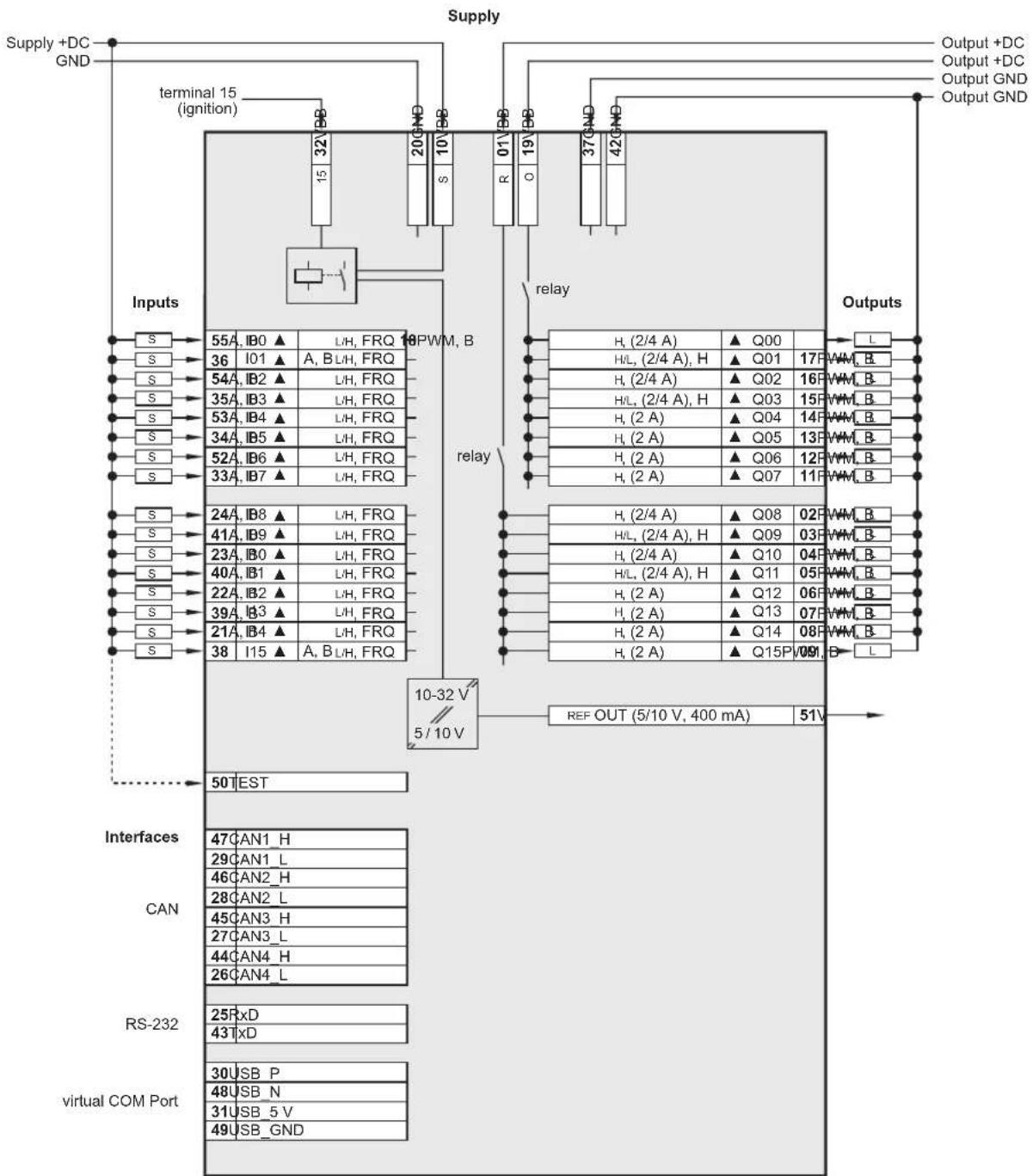
7.5 Wiring
CR7032 Technical data
Wiring
flowchart
graph TD
    A["Supply +DC GND"] --> B["terminal 15 (ignition)"]
    B --> C["Inputs"]
    C --> D["55A, IB0▲ L/H, FRQ 18PWM, B"]
    C --> E["36 I01▲ A, BLH, FRQ"]
    C --> F["54A, IB2▲ L/H, FRQ"]
    C --> G["35A, IB3▲ L/H, FRQ"]
    C --> H["53A, IB4▲ L/H, FRQ"]
    C --> I["34A, IB5▲ L/H, FRQ"]
    C --> J["52A, IB6▲ L/H, FRQ"]
    C --> K["33A, IB7▲ L/H, FRQ"]
    C --> L["24A, IB8▲ L/H, FRQ"]
    C --> M["41A, IB9▲ L/H, FRQ"]
    C --> N["23A, IB0▲ L/H, FRQ"]
    C --> O["40A, IB1▲ L/H, FRQ"]
    C --> P["22A, IB2▲ L/H, FRQ"]
    C --> Q["39A, IB3▲ L/H, FRQ"]
    C --> R["21A, IB4▲ L/H, FRQ"]
    C --> S["38 I15▲ A, BLH, FRQ"]
    B --> T["relay"]
    T --> U["H, (2/4 A) ▲ Q00"]
    T --> V["H/L, (2/4 A), H ▲ Q01 17FWM,B"]
    T --> W["H, (2/4 A) ▲ Q02 16FWM,B"]
    T --> X["H/L, (2/4 A), H ▲ Q03 15FWM,B"]
    T --> Y["H, (2 A) ▲ Q04 14FWM,B"]
    T --> Z["H, (2 A) ▲ Q05 13FWM,B"]
    T --> AA["H, (2 A) ▲ Q06 12FWM,B"]
    T --> AB["H, (2 A) ▲ Q07 11FWM,B"]
    T --> AC["H, (2/4 A) ▲ Q08 02FWM,B"]
    T --> AD["H/L, (2/4 A), H ▲ Q09 03FWM,B"]
    T --> AE["H, (2/4 A) ▲ Q10 04FWM,B"]
    T --> AF["H/L, (2/4 A), H ▲ Q11 05FWM,B"]
    T --> AG["H, (2 A) ▲ Q12 06FWM,B"]
    T --> AH["H, (2 A) ▲ Q13 07FWM,B"]
    T --> AI["H, (2 A) ▲ Q14 08FWM,B"]
    T --> AJ["H, (2 A) ▲ Q15P/09I B-L"]
    B --> AK["REF OUT (5/10 V, 400 mA) 51V"]
    AK --> AL["50TEST"]
    AL --> AM["Interfaces"]
    AM --> AN["CAN"]
    AM --> AO["RS-232"]
    AM --> AP["virtual COM Port"]
    style A fill:#f9f,stroke:#333
    style BB fill:#ccf,stroke:#333
    style BC fill:#cfc,stroke:#333
    style BD fill:#fcc,stroke:#333
    style BE fill:#ffc,stroke:#333
    style BF fill:#fcc,stroke:#333
    style BG fill:#fcc,stroke:#333
    style BH fill:#fcc,stroke:#333
    style BI fill:#fcc,stroke:#333
    style BJ fill:#fcc,stroke:#333
    style BK fill:#fcc,stroke:#333
    style BL fill:#fcc,stroke:#333
    style BM fill:#fcc,stroke:#333
    style BN fill:#fcc,stroke:#333
    style BO fill:#fcc,stroke:#333
    style BP fill:#fcc,stroke:#333
    style BQ fill:#fcc,stroke:#333
    style BR fill:#fcc,stroke:#333
    style BS fill:#fcc,stroke:#333
    style BT fill:#fcc,stroke:#333
    style BU fill:#fcc,stroke:#333
    style BV fill:#fcc,stroke:#333
    style BW fill:#fcc,stroke:#333
    style BX fill:#fcc,stroke:#333
    style BY fill:#fcc,stroke:#333
    style CA fill:#fcc,stroke:#333
    style CB fill:#fcc,stroke:#333
    style CC fill:#fcc,stroke:#333
    style CD fill:#fcc,stroke:#333
    style CE fill:#fcc,stroke:#333
    style CF fill:#fcc,stroke:#333
    style CG fill:#fcc,stroke:#333
    style CH fill:#fcc,stroke:#333
    style CI fill:#fcc,stroke:#333
    style CJ fill:#fcc,stroke:#333
    style CK fill:#fcc,stroke:#333
Abbreviations A
| Analogue | |
| BH | Binary high side |
| BL | Binary low side |
| FRQ | Frequency/pulse inputs |
| H | H-bridge function |
| PWM | Pulse width modulation |
| VBBs | Supply sensors/module |
| VBBo | Supply outputs |
| VBBR | Supply via relay |
| ▲ | Safety-compatible input/output |
8 Maintenance, repair and disposal
The unit is maintenance-free.
▶ Do not open the housing as the device does not contain any components which can be repaired by the user. The device must only be repaired by the manufacturer.
▶ Dispose of the device in accordance with the national environmental regulations.
9 Approvals/standards
Test standards and regulations ( 7 Technical data)
The EC declaration of conformity and approvals can be found at: www.ifm.com
- Functions and features
- WARNING
- Programming and important additions to these instructions
- Set-up
- Licences and trademarks
- Preliminary note
- Symbols used
- Warning signs used
- CAUTION
- NOTE
- Safety instructions
- General
- Target group
- Electrical connection
- Housing temperature
- Tampering with the device
- Electromagnetic compatibility
- Electrical welding on vehicles and plants
- Functions and features
- Installation
- Fixing
- Installation position
- Mounting surface
- Heat dissipation
- Electrical connection
- Wiring
- Ground connection
- Fuses
- Laying the supply and signal cables
- Frequency and analogue inputs
- Supply low-side digital outputs ( B_L )
- Connection technology
- USB interface
- Hardware requirement
- Short-circuit protection
- Set-up
- Interfaces and system requirements
- Programming via USB interface
- Install the USB drivers
- Install and define the virtual COM port
- Uninstall the drivers
- Technical data
- Mechanical and electric data
- CR7032
- Operating states
- Test standards and regulations
- Input characteristics
- Output characteristics
- Wiring
- CR7032 Technical data
- Maintenance, repair and disposal
- Approvals/standards
Brand : IFM
Model : CR7032
Category : Controller