B500 - Grinder RIDGID - Free user manual and instructions
Find the device manual for free B500 RIDGID in PDF.

| Product Type | Portable pipe beveling machine |
| Brand | RIDGID |
| Model | B500 |
| Dimensions (H x L x W) | 13.3 x 15.8 x 11.5 in (338 x 401 x 292 mm) |
| Weight | 52.5 lb (23.8 kg) with cutting head and crank |
| Power supply | 120 V, 12.5 A, 50/60 Hz or 230 V, 6.5 A, 50/60 Hz |
| No-load speed | 950 rpm |
| Motor power | 1.2 hp |
| Bevel angles | 30°, 37.5°, and 45° (depending on cutting head) |
| Pipe/sheet thickness | 0.188 to 0.50 in (4.8 to 12.7 mm) |
| Land width | 0 to 0.188 in (0 to 4.8 mm) in increments of ~1/32 in (0.8 mm) |
| Compatible materials | Steel and stainless steel (mainly A53 mild steel) |
| Standard equipment | Cutting head with 6 blades, mounting wrenches, grease, crank, instruction manual |
| Optional accessories | Additional cutting heads (30°, 37.5°, 45°), TBM-36 adapter, replacement blades |
| Sound pressure level | 92 dB(A) (K=3) |
| Sound power level | 105 dB(A) (K=3) |
| Maintenance | Cleaning after each use, monthly lubrication, blade rotation/replacement, brush inspection every 6 months |
| Safety | Mandatory eye and ear protection, avoid loose clothing, do not use drill or impact wrench, maintain safety distances |
| Warranty | Full Lifetime Warranty against defects in materials and workmanship |
Frequently Asked Questions - B500 RIDGID
User questions about B500 RIDGID
0 question about this device. Answer the ones you know or ask your own.
Ask a new question about this device
Download the instructions for your Grinder in PDF format for free! Find your manual B500 - RIDGID and take your electronic device back in hand. On this page are published all the documents necessary for the use of your device. B500 by RIDGID.
USER MANUAL B500 RIDGID
Transportable Pipe Beveller
natural_image
Red and black RIDGID hydraulic lift pump device with visible branding and wiring (no text or symbols on main body)Table of Contents
Recording Form For Machine Serial Number ....1
Safety Symbols....2
General Power Tool Safety Warnings
Work Area Safety 2
Electrical Safety 2
Personal Safety ....3
Power Tool Use And Care ....3
Service....3
Specific Safety Information
Beveller Safety 4
Description, Specifications And Standard Equipment
Description 4
Specifications....5
Standard Equipment 6
Icons 6
Pre-Operation Inspection....6
Set-Up And Operating Instructions ....7
Workpiece Preparation....7
Fixed Workpiece/Moving Beveller Set-up....8
Fixed Beveller/Rotating Pipe Set-up 8
Bevelling....10
Maintenance Instructions
Cleaning....14
Lubrication 14
Rotating/Replacing Cutter Inserts ....14
Changing Cutter Heads 15
Replacing Carbon Brushes ....15
Breaker....16
Wear Plates 16
Gib Plate Adjustment 16
Optional Equipment 16
Machine Storage....17
Service And Repair....17
Disposal 17
EC Declaration....Inside Back Cover
Lifetime Warranty ....Back Cover
*Original Instructions - English
Transportable Pipe Beveller
natural_image
Mechanical device with RIDGID branding and attached cable, no visible text or symbols on the main body.
WARNING!
Read this Operator's Manual carefully before using this tool. Failure to understand and follow the contents of this manual may result in electrical shock, fire and/or serious personal injury.
| Model B-500 Transportable Pipe Beveller | |
| Record Serial Number below and retain product serial number which is located on nameplate. | |
| Serial No. | |
Safety Symbols
In this operator's manual and on the product, safety symbols and signal words are used to communicate important safety information. This section is provided to improve understanding of these signal words and symbols.

This is the safety alert symbol. It is used to alert you to potential personal injury hazards. Obey all safety messages that follow this symbol to avoid possible injury or death.

DANGER
DANGER indicates a hazardous situation which, if not avoided, will result in death or serious injury.

WARNING
WARNING indicates a hazardous situation which, if not avoided, could result in death or serious injury.

CAUTION
CAUTION indicates a hazardous situation which, if not avoided, could result in minor or moderate injury.
NOTICE
NOTICE indicates information that relates to the protection of property.

This symbol means read the operator's manual carefully before using the equipment. The operator's manual contains important information on the safe and proper operation of the equipment.

This symbol means always wear safety glasses with side shields or goggles and hearing protection while using this equipment to reduce the risk of injury.

This symbol indicates the risk of electrical shock.

This symbol indicates the risk of hands, fingers or other body parts being cut by the rotating or moving parts.

This symbol indicates the risk of machine tipping, causing striking or crushing injuries.

This symbol indicates that a drill, impact tool, or other power tool should not be used to drive this device.
General Power Tool Safety Warnings\*
WARNING
Read all safety warnings, instructions, illustrations and specifications provided with this power tool. Failure to follow all instructions listed below may result in electric shock, fire and/or serious injury.
SAVE ALL WARNINGS AND INSTRUCTIONS FOR FUTURE REFERENCE!
The term "power tool" in the warnings refers to your mains-operated (corded) power tool or battery-operated (cordless) power tool.
Work Area Safety
- Keep work area clean and well lit. Cluttered or dark areas invite accidents.
- Do not operate power tools in explosive atmospheres, such as in the presence of flam mable liquids, gases, or dust. Power tools create sparks which may ignite the dust or fumes.
- Keep children and bystanders away while operating a power tool. Distractions can cause you to lose control.
Electrical Safety
- Power tool plugs must match the outlet. Never modify the plug in any way. Do not use any adapter plugs with earthed (grounded) power tools. Un-modified plugs and matching outlets will reduce risk of electric shock.
- Avoid body contact with earthed or grounded surfaces such as pipes, radiators, ranges and refrigerators. There is an increased risk of electrical shock if your body is earthed or grounded.
- Do not expose power tools to rain or wet conditions. Water entering a power tool will increase the risk of electrical shock.
-
Do not abuse the cord. Never use the cord for carrying, pulling or unplugging the power tool. Keep cord away from heat, oil, sharp edges or moving parts. Damaged or entangled cords increase the risk of electric shock.
-
When operating a power tool outdoors, use an extension cord suitable for outdoor use. Use of a cord suitable for outdoor use reduces the risk of electric shock.
- If operating a power tool in a damp location is unavoidable, use a ground fault circuit interrupter (GFCI) protected supply. Use of a GFCI reduces the risk of electric shock.
Personal Safety
- Stay alert, watch what you are doing and use common sense when operating a power tool. Do not use a power tool while you are tired or under the influence of drugs, alcohol, or medication. A moment of inattention while operating power tools may result in serious personal injury.
- Use personal protective equipment. Always wear eye protection. Protective equipment such as dust mask, non-skid safety shoes, hard hat, or hearing protection used for appropriate conditions will reduce personal injuries.
- Prevent unintentional starting. Ensure the switch is in the OFF-position before connecting to power source and/or battery pack, picking up or carrying the tool. Carrying power tools with your finger on the switch or energizing power tools that have the switch ON invites accidents.
- Remove any adjusting key or wrench before turning the power tool ON. A wrench or a key left attached to a rotating part of the power tool may result in personal injury.
- Do not overreach. Keep proper footing and balance at all times. This enables better control of the power tool in unexpected situations.
- Dress properly. Do not wear loose clothing or jewel ry. Keep your hair and clothing away from moving parts. Loose clothes, jewelry, or long hair can be caught in moving parts.
- If devices are provided for the connection of dust extraction and collection facilities, ensure these are connected and properly used. Use of dust collection can reduce dust-related hazards.
- Do not let familiarity gained from frequent use of tools allow you to become complacent and ignore tool safety principles. A careless action can cause severe injury within a fraction of a second.
Power Tool Use And Care
- Do not force the power tool. Use the correct power tool for your application. The correct power tool will do the job better and safer at the rate for which it is designed.
- Do not use the power tool if the switch does not turn it ON and OFF. Any power tool that cannot be controlled with the switch is dangerous and must be repaired.
- Disconnect the plug from the power source and/or remove the battery pack, if detachable, from the power tool before making any adjustments, changing accessories, or storing power tools. Such preventive safety measures reduce the risk of starting the power tool accidentally.
- Store idle power tools out of the reach of children and do not allow persons unfamiliar with the power tool or these instructions to operate the power tool. Power tools are dangerous in the hands of untrained users.
- Maintain power tools. Check for misalignment or binding of moving parts, breakage of parts and any other condition that may affect the power tool's operation. If damaged, have the power tool repaired before use. Many accidents are caused by poorly maintained power tools.
- Keep cutting tools sharp and clean. Properly maintained cutting tools with sharp cutting edges are less likely to bind and are easier to control.
- Use the power tool, accessories and tool bits etc. in accordance with these instructions, taking into account the working conditions and the work to be performed. Use of the power tool for operations different from those intended could result in a hazardous situation.
- Keep handles and grasping surfaces dry, clean and free from oil and grease. Slippery handles and grasping surfaces do not allow for safe handling and control of the tool in unexpected situations.
Service
- Have your power tool serviced by a qualified repair person using only identical replacement parts. This will ensure that the safety of the power tool is maintained.
Specific Safety Information
WARNING
This section contains important safety information that is specific to this tool.
Read these precautions carefully before using the Model B-500 Transportable Pipe Beveller to reduce the risk of electrical shock or other serious injury.
SAVE THESE INSTRUCTIONS!
Keep this manual with machine for use by the operator.
Beveller Safety
- Always wear appropriate eye protection and hearing protection. Cutting tools can break or shatter. Cutting produces chips that can be thrown or fall into eyes. Cutting produces high noise levels that over time can damage your hearing.
- Always wear appropriate personal protective equipment. Face shields, long sleeves, safety shoes, hard hat, and other equipment as appropriate will reduce the risk of injury.
- Do not wear loose clothing when operating machine. Keep sleeves and jackets buttoned. Do not reach across machine. Clothing can be caught by the machine resulting in entanglement.
- Keep bystanders clear of work area. Guard or barricade minimum of 6 feet (2 meter) around the working area. Chips or broken cutting tools can be thrown and cause injury beyond immediate area of operation. A guard or barricade that provides a clearance around the work piece will reduce the risk of injury.
- One person must control the work process and the beveller ON/OFF switch. Only the operator should be in the work area when the machine is running. This helps reduce the risk of injury.
- Properly support work piece and beveller. Make sure the beveller is secure to the work piece. This will reduce the risk of striking and crushing injuries from tipping and falling pipe and equipment.
- Do not start the beveller with the cutter inserts touching the work piece. Let the cutter head reach full speed before carefully feeding it into the work piece. The cutter may bind, walk or kickback if the tool is started while in contact with the work piece.
-
Keep hands away from rotating cutter head. Allow parts to come to a complete stop before handling the tool or pipe. This practice will reduce the chance of entanglement in rotating parts.
-
Do not use power tools such as a drill or impact to drive the beveller. Only drive beveller by hand.
Use of power to drive the beveller can increase the risk of injury. - Avoid breathing of dust created from pipe bevelling. Some dust created may contain chemicals known to cause cancer, birth defects or other serious personal injury. Consider the pipe material and coatings when determining appropriate respiratory protection, including things such as lead based paint.
Your risk from these exposures varies, depending on how often you do this type of work and the concentration of dust. To reduce your exposure to these chemicals, work in a well ventilated area, and use respiratory protection selected based on appropriate regulations and standards, such as ANSI Z88.2 and OSHA.
- Do not modify beveller or use for any other purpose. Other uses or modifying the beveller for other applications may damage the tool, damage the attachments and/or cause personal injury.
- Read and understand these instructions and the instructions and warnings for all equipment and materials being used before operating this tool to reduce the risk of serious personal injury.
The EC Declaration of Conformity (890-011-320.10) will accompany this manual as a separate booklet when required.
If you have any question concerning this RIDGI product:
- Contact your local RIDGID® distributor.
- Visit RIDGID.com to find your local Ridge Tool contact point.
- Contact Ridge Tool Technical Service Department at rttechservices@emerson.com, or in the U.S. and Cana da call (800) 519-3456.
Description, Specifications And Standard Equipment
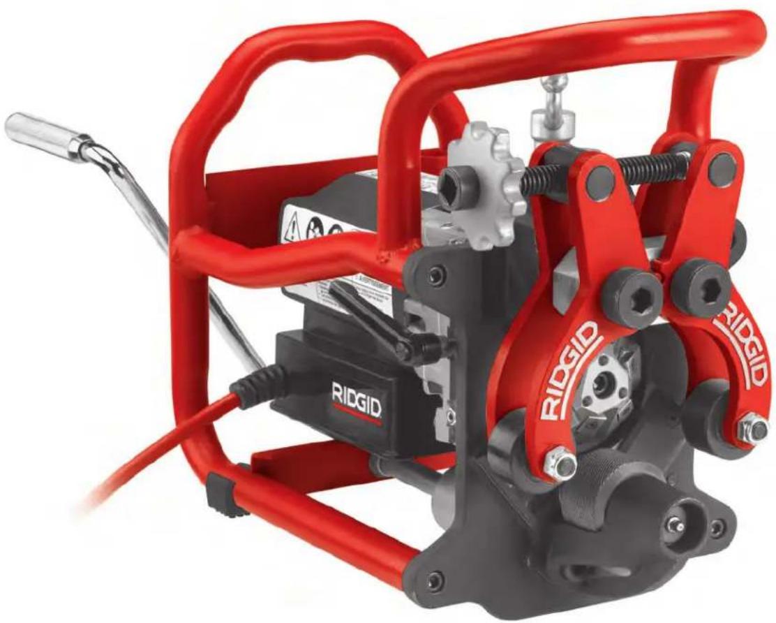
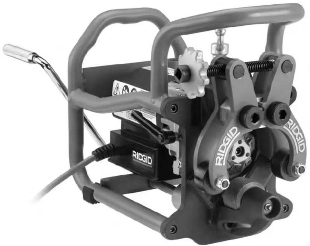
Description
The RIDGID® Model B-500 Transportable Pipe Beveller is used for bevelling most steel and stainless steel pipe ends and plate edges on material up to 0.5" (13 mm) thick in preparation for welding. Conical cutter heads with replaceable cutter inserts (see Figure 24) are driven by a motor/gearbox to produce 30°, 37.5°, or 45° bevels (with the correct cutter head).
The bevel is formed in a single pass without the need of any further dressing. No coolant or cutting oil is used. Land width can be adjusted in approximately 132 " (0.8 mm) increments from 0 to 0.188" (0 to 4.8 mm). The bev-
eller securely grips the work piece between guide rolls and a drive roll. A detachable, hand crank is included to manually move the cutter head through the material being bevelled. Indicator lights are supplied to give feedback on proper cranking speed. The frame helps protect the motor/-gearbox and aids in beveller handling.
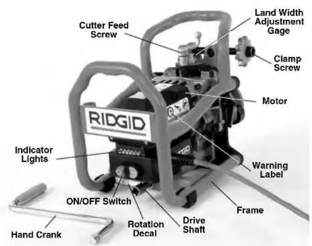
text_image
Cutter Feed Screw RIDGID Indicator Lights ON/OFF Switch Hand Crank Rotation Decal Drive Shaft Frame Warning Label Motor Clamp Screw Land Width Adjustment Gage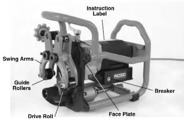
text_image
Instruction Label Swing Arms Guide Rollers Drive Roll Face Plate Breaker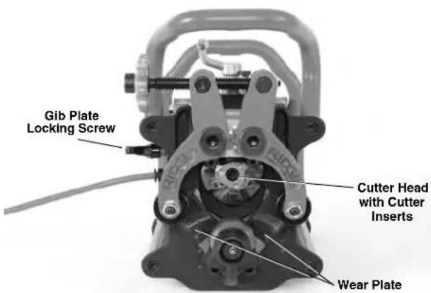
text_image
Gib Plate Locking Screw Cutter Head with Cutter Inserts Wear PlateFigure 1 – Model B-500 Beveller
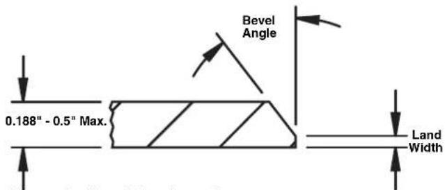
text_image
0.188" - 0.5" Max. Bevel Angle Land WidthFigure 2 - Bevel Configuration
Specifications
Capacity Diameter.....Minimum – 4" IPS Pipe Maximum – Flat Plate
Pipe Wall/Plate
Thickness....Minimum - 0.188" (4.8 mm) Maximum - 0.50" (12.7 mm) Material thickness cannot vary by more than 0.031" (0.8 mm)
Pipe/Plate
Orientation......Horizontal (See Figure 6.)
Bevel Angles....37.5°, 30° and 45° (with Correct Cutter Head)
Land Width ....0 to 0.188" (4.8 mm) in approximately 132 " (0.8 mm) increments
Materials* ......Most Steel, Stainless Steel
*Beveller cutting head and inserts are optimized for standard A53 mild steel pipe. Reduced insert life can be expected on other materials.
*Ability to bevel depends on a variety of factors, including material type, chemistry, hardness, amount of material being removed and other factors. In some cases, bevels may not be able to be made or may result in cutter insert damage. If there are any questions about the specific material to be bevelled, contact Ridge Tool Technical Service Department.
No Load Operating
Speed N _0 ....950/min
Motor:
Type ....Universal
Horsepower .....1.2 HP
Rating ....120V, 12.5 Amps, 50/60 Hz 230V, 6.5 Amps, 50/60 Hz
Dimensions:
Height 13.3" (33.8 cm)
Length.....15.8" (40.1 cm)
Width.....11.5" (29.2 cm)
Weight.....52.5 lbs (23.8 kg) with Cutter Head and Crank Handle
Sound Pressure ( I_ A )* 92 dB(A), K=3
Sound Power (lWA)* 105 dB(A), K=3
* Sound measurements are measured in accordance with a standardized test per Standard 62841-1.
- Sound emissions may vary due to your location and specific use of these tools.
- Daily exposure levels for sound need to be evaluated for each application and appropriate safety measures taken when needed. Evaluation of exposure levels should consider the time a tool is switched off and not in use. This may significantly reduce the exposure level over the total working period.
Standard Equipment
The RIDGID® Model B-500 Transportable Pipe Beveller comes with:
- Cutter Head, with one set of six cutter inserts (In - stalled)
• T15 Wrench for cutter Insert Screws - Anti-Seize Grease for cutter Insert Screws
• 1" Spanner Wrench - ^5/_16 " Hex Key
- Operator's Manual

natural_image
Black Riddig ID tool kit with multiple tools including wrench, wrench, and trowel (no visible text or labels)Figure 3 – Standard Equipment
Icons

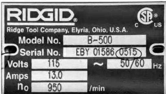
text_image
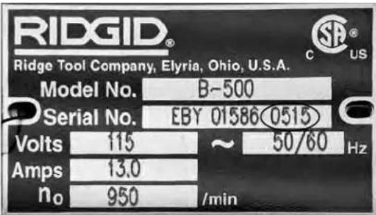
RIDGID® Ridge Tool Company, Elyria, Ohio, U.S.A. Model No. B-500 Serial No. EBY 01586 0515 Volts 115 ~ 50/60 Hz Amps 13.0 no 950 /minFigure 4 – Machine Serial Number
The Model B-500 Beveller serial number plate is located on the side of the motor. The last 4 digits indicate the month and year of manufacture.
NOTICE Selection of appropriate materials and installation, joining and forming methods is the responsibility of the system designer and/or installer. Selection of improper materials and methods could cause system failure.
Stainless steel and other corrosion resistant materials can be contaminated during installation, joining and forming. This contamination could cause corrosion and premature failure. Careful evaluation of materials and methods for the specific service conditions, including chemical and temperature, should be completed before any installation is attempted. (See NOTICE in Workpiece Preparation section.)
Pre-Operation Inspection
WARNING

natural_image
Two black-and-white icons: a stick figure holding a megaphone and a circular device with a lock (no text or symbols)Before each use, inspect your beveller and correct any problems to reduce the risk of serious injury from electric shock, entanglement, crushing injuries and other causes and prevent beveller damage.
- Make sure that the beveller is unplugged and press the OFF button.
- Clean any oil, grease, dirt, or chips from the beveller, including the handles and controls. This aids inspection and helps prevent the machine or control from slipping from your grip. Clean and maintain the machine per the Maintenance Instructions.
- Inspect the beveller for the following:
- Inspect the cord and plug for damage or modification.
• Proper assembly, maintenance and completeness.
- Any broken, worn, missing, misaligned or binding parts or other damage.
- Drive roll knurl is clean and in good condition. If needed, clean with a wire brush. Worn or dirty drive roll knurls can cause slippage or tracking issues in use. Dirty rolls and knurls can cause ferrous contamination of stainless steel.
- Presence and readability of the warning and instruction labels (See Figure 1).
- Confirm fasteners and cutter head are secure.
- Confirm that drive shaft only turns in the clockwise direction (as marked on decal).
- Inspect the cutting edges of the cutter inserts in the cutter head for wear, deformation, chips or other issues. Confirm that the cutter inserts are secure. Dull, damaged or loose cutting inserts can damage the tool, produce poor quality cut and increase the risk of injury.
- Any other condition which may prevent safe and normal operation.
If any problems are found, do not use the tool until the problems have been repaired.
- Inspect and maintain any other equipment being used per its instructions to make sure it is functioning properly.
Set-Up And Operating Instructions
WARNING

natural_image
Four black-and-white pictograms showing different behaviors: a phone icon, a no-smoking symbol, a falling gear with cracks, and a person pushing a bucket (no text or symbols present)Always wear appropriate eye protection and hearing protection. Cutting tools can break or shatter. Cutting produces chips that can be thrown or fall into eyes. Cutting produces high noise levels that over time can damage your hearing.
Do not wear loose clothing when operating machine. Keep sleeves and jackets buttoned. Do not reach across machine. Clothing can be caught by the machine resulting in entanglement.
Keep bystanders clear of work area. Guard or barricade minimum of 6 feet (2 meter) around the working area. Chips or broken cutting tools can be thrown and cause injury beyond immediate area of operation. A guard or barricade that provides a clearance around the work piece will reduce the risk of injury.
One person must control the work process and the Beveller ON/OFF switch. Only the operator should be in the work area when the machine is running. This helps reduce the risk of injury.
Properly support work piece and beveller. Make sure the beveller is secure to the work piece. This will reduce the risk of striking and crushing injuries from tipping and falling pipe and equipment.
Do not start the Beveller with the cutter inserts touching the work piece. Let the cutter head reach full speed before carefully feeding it into the work piece. The cutter head may bind, walk or kickback if the tool is started while in contact with the work piece.
Keep hands away from rotating cutter head. Allow parts to come to a complete stop before handling the tool or pipe. This practice will reduce the chance of entanglement in rotating parts.
Do not use power tools such as a drill or impact to drive the beveller. Only drive beveller by hand. Use of power to drive the beveller can increase the risk of injury.
Set-up and operate the beveller according to these
procedures to reduce the risk of injury from electric shock, entanglement, striking, crushing and other causes, and to help prevent machine damage.
-
Check work area for:
-
Adequate lighting.
- Flammable liquids, vapors or dust that may ignite. If present, do not work in area until sources have been identified and corrected. The machine is not explosion proof and can cause sparks.
- Clear, level, stable and dry place for all equipment and operator.
- Properly grounded electrical outlet of the correct voltage. A three-prong or GFCI outlet may not be properly grounded. If in doubt, have outlet inspected by a licensed electrician.
-
Clear path to electrical outlet that does not contain any potential sources of damage for the power cord.
-
When using the beveller, you will generally need to use extension cords. Choose an extension cord that:
-
Is in good condition.
- Has a grounded (earthed) plug like on the beveller.
• Is rated for outdoor use. - Has sufficient wire size. For extension cords up to 50' (15.2 m) long use 14 AWG (1.5 mm) or heavier. For extension cords 50'-100' (15.2 m - 30.5 m) long use 12 AWG (2.5 mm) or heavier.
With dry hands, plug the extension cord into the outlet. Run the extension cord along a clear path to the beveller. Keep all connections dry and off the ground. Leave excess cord at the base of the machine to allow for machine movement in the Fixed Workpiece/ Moving Beveller configuration (see Figure 20A & B). Do not plug the beveller in at this time.
- Make sure all equipment has been properly inspected.
- Keep bystanders clear of work area, set up guards or barricades to create a minimum of 6 feet (2 m) of clearance around the workpiece and beveller. This helps to prevent bystanders from being struck by chips during use.
Workpiece Preparation
Inspect the work piece to be bevelled and confirm that the Model B-500 Beveller is a correct tool for the job. See Specifications.
For pipe, the pipe end must be square within 0.062" (1.6 mm), see Figure 5. The beveller follows the cut on the end of the pipe and does not square the end of the pipe. For plate, the edge to be bevelled must be straight, without curves. The bevelled edge will be no straighter than the ini-
tial cut. Bevelling non-square edges could cause tracking issues and can affect the bevel quality.
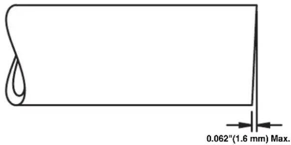
text_image
0.062"(1.6 mm) Max.Figure 5 – Pipe Squareness Requirements
The beveller will work on displacement cut (cutting wheel), saw cut or torch cut edges. Prior to bevelling, remove torch cutting slag build up, pipe weld seams over t_32 (0.8 mm) high, large burrs and other debris on both sides of the edge to be bevelled within 3" (75 mm) of the edge. This allows the beveller to grip and drive on the material. It may be necessary to remove oil or other coatings on the material to be bevelled to ensure beveller tracking.
There must be at least 3" of unobstructed straight pipe or flat plate from the edge to be bevelled for the beveller to mount and drive on. Do not use on curved material, such as elbows or other fittings.
NOTICE To prevent ferrous contamination of stainless steel, make sure that the drive and guide rolls are clean and debris free. Thoroughly clean with a stainless steel brush. Change inserts – use dedicated inserts for stainless steel. Best practice is to dedicate a beveller for stainless steel.
NOTICE Do not use the beveller on material that is connected to a welder. If the beveller is connected to a workpiece during welding processes, it can damage the beveller circuitry.
Fixed Workpiece/Moving Beveller Set-Up
The beveller is designed for use on horizontal pipe and plate. It may also be used for pipe ends above horizontal. See Figure 6 for examples. Use in other orientations can allow the beveller and chips to fall on the operator, and is not allowed.
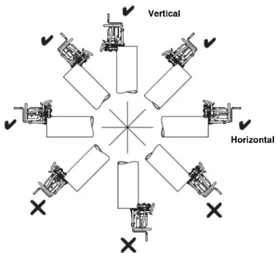
text_image
Vertical HorizontalFigure 6 – Acceptable (√) and Unacceptable (✗) pipe orientations
Make sure that the work piece to be bevelled is solidly mounted and stable. Work piece and support must be able to withstand the weight of the beveller and the force and torque required for bevelling without moving or turning. When using a pipe vise, make sure that it is properly sized and secured to prevent tipping during use. For longer lengths of pipe, use appropriate pipe stands to support extra length.
When used on flat plate, the beveller cannot be used with in 6 inches of the end of the edge. Both guide rollers must contact the plate to hold the beveller in place (See Figure 16).
If bevelling in place, make sure that there is sufficient room for the beveller to fit in place and move along work piece.
Fixed Beveller/Rotating Pipe Set-Up
With the Model TBM-36 Beveller Adapter (optional equipment) (See Figure 7) the B-500 Beveller is mounted on a RIDGID 450 or 460 series TRISTAND chain pipe vise. The beveller is held stationary in use while the pipe rotates, increasing convenience and allowing shorter pieces of pipe to be beveled. This can be used for pipe up to 36" (900 mm) in diameter.
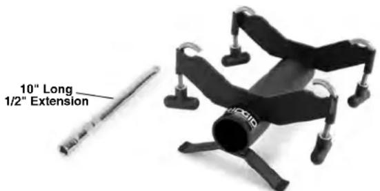
text_image
10" Long 1/2" ExtensionFigure 7 – TBM-36 Beveller Adapter
-
Inspect and set up the RIDGID® 450 or 460 Series Portable TRISTAND chain pipe vise as per its instructions. If desired, anchor the rear leg of the Portable TRISTAND chain pipe vise for greater stability. Do not anchor the front legs. Anchoring the front legs of the stand can prevent slight stand movement needed for good tracking.
-
Place the cylindrical body of the adapter in the V-jaw of the vise as shown in Figure 8. Locate the key into the slot of the vise jaw for proper positioning and stability.
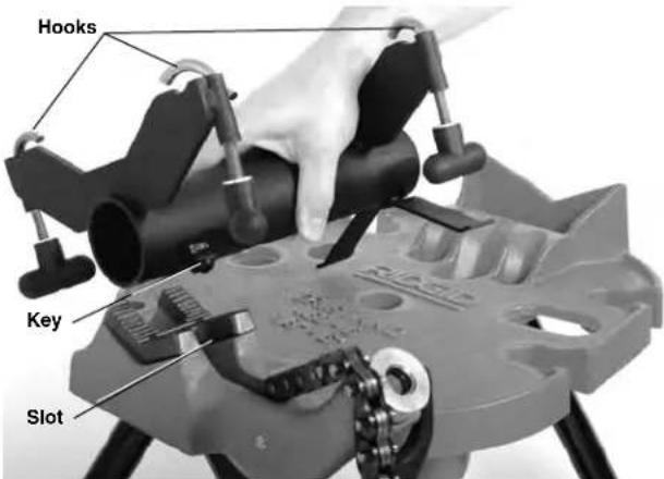
text_image
Hooks Key SlotFigure 8 – Mounting the Adapter on Vise
3 Place the vise chain over the body of the adapter and securely tighten the chain to hold the adapter in place.
-
Fully loosen the adapter hook knobs and move the hooks outwards.
-
Securely grasp the beveller and place on the adapter as shown in Figure 9.

text_image
RICKID HooksFigure 9 – Securing Beveller to Adapter
-
Move the hooks over the beveller frame and securely tighten the knobs (Figure 9).
-
Make sure the stand and equipment are stable.
-
Install the supplied 10" long 12 " drive extension in the Beveller drive shaft (see Figure 10).
-
When beveling pipe less than 12" (300 mm) long and less than 50 pounds (22 kg), as long as the beveller and Portable TRISTAND Pipe Vise are stable and secure, no pipe stand is needed to support the pipe. Pipe is placed directly on the drive roll and secured with the guide rolls (Figure 10).
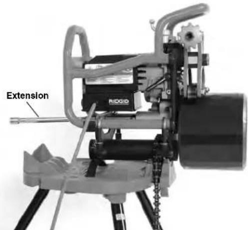
text_image
Extension RIGIDFigure 10 – Fixed Beveller, Pipe under 12" Long, under 50 Pounds
If beveling pipe longer than 12" (300 mm) or more than 50 lbs (22 kg), the pipe must be supported with appropriate pipe stands to reduce the risk of the pipe and equipment tipping and falling. Stands must be equipped with rollers to allow the pipe to rotate while beveling. Improper pipe supports or supporting the pipe by hand can cause tipping or falling pipe and equipment.
Place the pipe stands in line with beveller drive roll. Always use at least two pipe stands if possible. Pipe upper inside diameter should be the same height or up to 18 " (3mm) higher than the upper edge of the beveller drive roll prior to gripping (see Figure 11). Pipe should be parallel to the beveller drive roll. Do not place the inside diameter of the pipe lower than the upper edge of the drive roll – this can decrease stability and tracking.
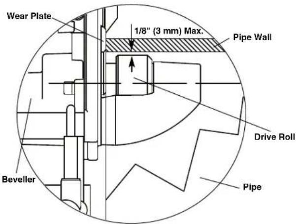
text_image
Wear Plate 1/8" (3 mm) Max. Pipe Wall Drive Roll Beveller PipeFigure 11 – Fixed Beveller, Pipe Position relative to Beveller Drive Roll (Cut Away Pipe - Prior To Gripping)
natural_image
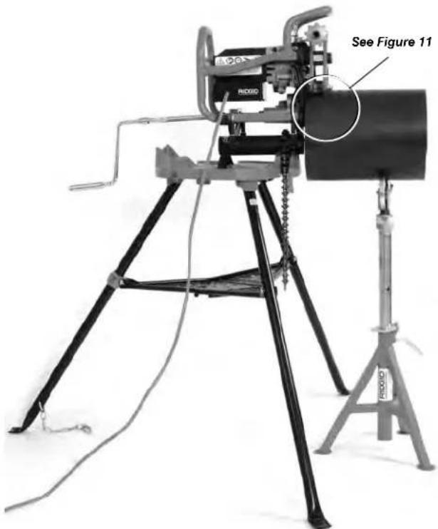
Retrobox rig with tripod-mounted platform and attached device, labeled 'See Figure 11' (no readable text beyond label)Figure 12 – Fixed Beveller, Short Pipe, One Pipe Stand
When used with short sections of the pipe and one pipe stand, the pipe will be supported on the beveller drive roll and the pipe stand (see Figure 12). When used with longer pipes and multiple pipe stands, the pipe will be supported on the stands, as shown in Figure 13.
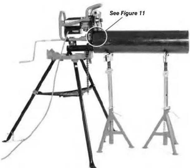
text_image
See Figure 11Figure 13 – Fixed Beveller, Long Pipe, Multiple Pipe Stands
The set-up and tracking of the pipe to Beveller can be confirmed prior to bevelling. Following the bevelling instructions, but without turning machine ON, tighten the clamp screw hand tight plus 3/4 turn to grip the pipe. Insert the hand crank and rotate to drive the pipe around. Pipe end should stay flush to wear plates (Figure 15B) as pipe rotates. If not, the set-up will need to be adjusted.
Bevelling
The B-500 Transportable Pipe Beveller can be used in two configurations, either with the work piece fixed and the beveller moving along it (Fixed Workpiece/Moving Beveller) or with the beveller fixed on the Model TBM-36 Beveller Adapter and the pipe moving relative to the beveller (Fixed Beveller/Rotating Pipe) See Set-Up information for these configurations.
Due to differing material characteristics, a test bevel should always be performed before the first bevel of the day or when changing material type, material thickness, bevel angle or land width.
A label is provided on the beveller motor with basic operation information. The label steps follow the steps of this section. This label is not a substitute for operator's manual which contains all of the information for proper use.
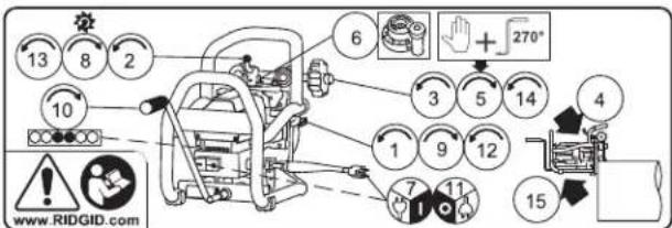
text_image
13 8 2 10 6 + 270° 3 5 14 1 9 12 7 11 15 4 www.RIDGID.comFigure 14 – Instruction Label
- Confirm that the gib plate lock screw is loose.
- Turn the cutter feed screw counter clockwise to fully retract the cutter head (away from the drive roll).
- Turn the clamp screw to open the swing arms to position wide enough for mounting to work piece.
- Bringing the beveller and workpiece together.
Fixed Workpiece/Moving Beveller
Confirm that the beveller and workpiece have been properly set up.
Securely grasp the beveller and place on the pipe with guide rollers on the outside diameter (guide rolls to the side that gets the bevel for flat plate) and drive roll inside the pipe (side away from the bevel). Make sure the wear plates on the beveller are flush to the end of the pipe or plate edge (Figure 15B). Do not hit the pipe or plate with the Cutter Head to prevent damage to the inserts. Hold beveller until secure to work piece.

text_image
Clamp Screw Gib Plate Lock ScrewFigure 15A – Placing Beveller on Pipe
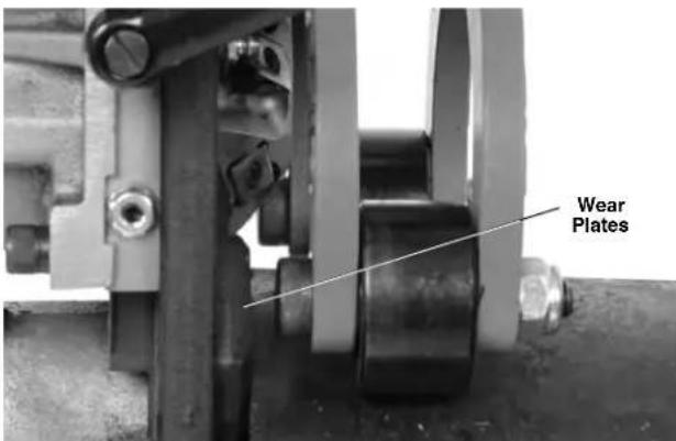
text_image
Wear PlatesFigure 15B – Wear Plate Flush To End of Pipe
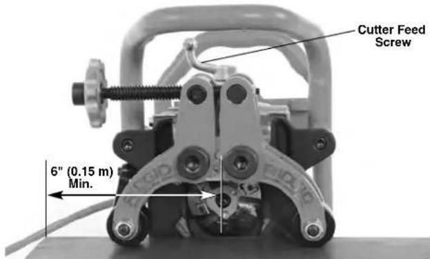
When used on flat plate, the beveller cannot be used within 6 inches of the end of the edge. Both guide rollers must contact the plate to hold the beveller in place (See Figure 16).
text_image
Cutter Feed Screw 6" (0.15 m) Min.Figure 16A – Beveller On Plate
natural_image
Industrial machine with visible pipes and control components, no text or symbols presentFigure 16B – Installing Beveller on Plate
Fixed Beveller/Rotating Pipe
Confirm that the beveller, pipe stands and pipe have been properly set up (see Figures 10, 12 and 13).
Place the pipe over the beveller drive roll. Make sure the wear plates on the beveller are flush to the end of the pipe or plate edge. Do not hit the Cutter Head with the workpiece to prevent damage to the inserts. Hold pipe until secured by the beveller.
- Tighten the clamp screw hand tight plus an additional
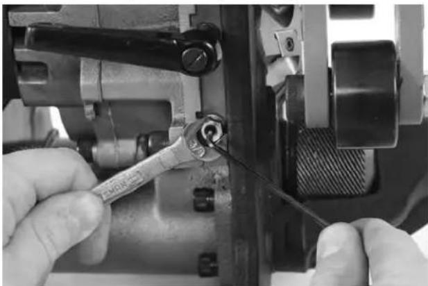
^3/_4 turn (270°) (Figure 17) with the supplied hand crank to grip the material between the guide rollers + 270° and the drive roll. Make sure that the beveller is secure to the material and the beveller and material is stable. Remove the hand crank. Do not leave the hand crank on the clamp screw. Do not attempt to bevel unless the pipe is secure to the beveller.

natural_image
Man in checkered shirt using a sewing machine (no visible text or symbols)Figure 17A – Hand Tighten Clamp Screw
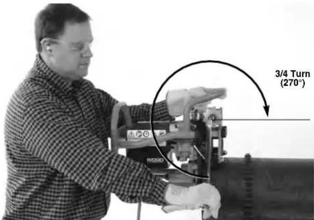
text_image
3/4 Turn (270°)Figure 17B - Tighten Clamp Screw Additional Turn (270°)
- Set the desired bevel land width (Figure 18) using
the land width adjustment gage. If set to "0" there will be no land on the end of the pipe. Each step on the land width adjustment gage is approximately a 132 " (0.8 mm) different from the adjacent step. (1 \~ 0.03" (0.8 mm) land width, 2 \~ 0.06" (1.6 mm), etc. Move the needed step of the gage so it aligns under the head of the stop.
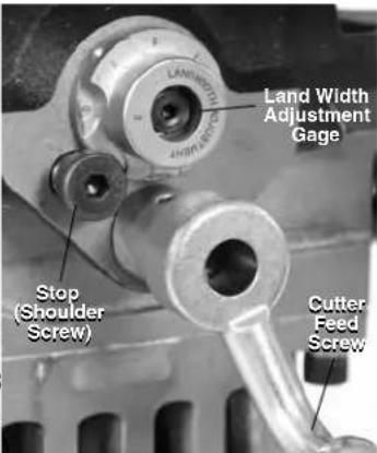
text_image
Land Width Adjustment Gage Stop (Shoulder Screw) Cutter Feed ScrewFigure 18 – Land Width Adjustment Gage Setting
- Confirm that the cutter head is fully retracted and not in contact with the work piece. With dry hands, plug the
beveller power cord into a properly grounded outlet/extension. All indicator lights should be illuminated.
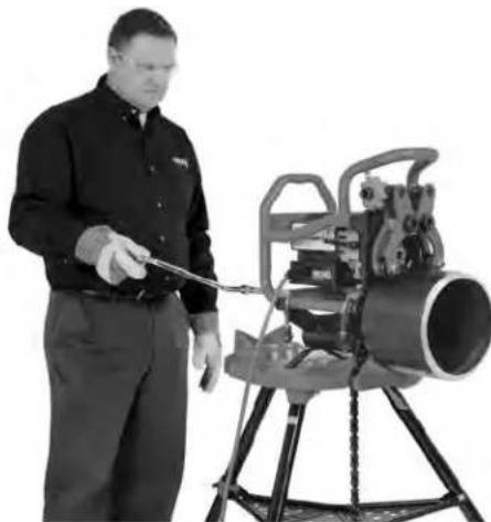
Assume a proper operating position (Figure 19).
- Stand at the back of the machine, facing the hand crank with good access to the ON/OFF switch. In case of emergency you must be able to turn the machine OFF.
- Be sure you have good balance and do not have to overreach.
Depress the ON button (I). After motor comes up to speed, yellow indicator lights should be ON.

natural_image
Man operating a large industrial machine with a tool, no visible text or symbolsFigure 19 – Proper Operating Position
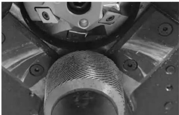
-
Using a smooth continuous clockwise rotation of the cutter feed screw (Figure 18); engage the cutter head into the work piece until the stop contacts the land width adjustment gage. Do not use cutting oil or coolant.
-
Tighten the gib plate locking screw to lock the cutter head into position (Figure 15). If gib plate locking screw is not securely tightened, the cutting inserts could become damaged.
-
Insert the hand crank into the drive shaft or extension. Using a controlled uninterrupted motion, start rotating the hand crank in a clockwise direction to bevel (Figure 20).
It is important to provide proper rotational speed to prolong the life of the cutting inserts. Monitor the LED indicator lights on the rear of the unit. Green indicates the proper speed. Yellow indicates that you need to rotate the handle faster, Red indicates to rotate the handle slower. (See Figure 21.)
The crank should only turn clockwise when viewed from the back of the beveller. Do not drive the beveller with a drill, impact or other power tool – drive by hand only. Do not use cutting oil or coolant.
In some cases, chips will build up between the work piece and the guide rollers. In most cases, the guide rollers will ride over the chips with no issue other than a slight increase in cranking force. If the unit binds or chips need to be removed during bevelling, turn the tool off and unplug it prior to removing chips or removing the pipe.

natural_image
Man in checkered shirt operating industrial machine next to large pipe (no visible text or symbols)Figure 20A – Bevelling Operation (Fixed Workpiece/Moving Beveller)

natural_image
Man in checkered shirt observing a large cylindrical device mounted on a stand (no visible text or symbols)Figure 20B – Bevelling Operation (Fixed Workpiece/Moving Beveller)
natural_image
Man operating a large cylindrical machine on a tripod stand (no visible text or symbols)Figure 20C – Bevelling Operation (Fixed Beveller/Rotating Pipe)

natural_image
Close-up of a mechanical device with visible components and a 'RIDGID' logo on the top (no readable text beyond branding)Indicator Lights
| Indicator Lights | Lights Illuminated Condition |
 | All Plugged in, switch OFF |
 | Two Yellow Crank speed too slow. |
 | One Yellow/OneGreen |
 | Two Green Optimum crank speed. |
 | One Green/OneRed |
 | Two Red Crank speed too fast. |
Figure 21 – Indicator Lights
Continually monitor the cord position (moving beveller only) and tracking of the beveller to the workpiece.
Make sure the cord stays clear of the cutter head. As the bevel is formed, make sure that the wear plates stay flush to the end of pipe or plate edge. Stop rotating the hand crank and press the OFF (O) button. If:
• The wear plates move away from the work piece.
• The cutters do not engage the work piece.
• The process needs to be stopped for any reason.
This will help prevent the beveller from tracking off the work piece. Repeat procedure starting at step one to continue bevel.
Continue rotating the crank until the bevel is complete.
- When bevel is complete, press the OFF button (O) and make sure the cutter head comes to a complete stop. Unplug the beveller from the extension (Moving Beveller Only).
- Loosen the gib plate locking screw to unlock the cutter head.
- Fully retract the cutter head using the cutter feed screw.
- Making sure that the beveller and workpiece are secure, loosen the clamp screw to open the swing arms to release work pipe.
- Separate the beveller and work piece. Be careful of sharp edges on the pipe. Be careful not to hit the Cutter Head with the pipe to prevent damage to the inserts.
Maintenance Instructions
WARNING
Make sure the beveller is unplugged and press the OFF button before performing any maintenance or making any adjustments.
Always wear eye protection.
Maintain beveller according to these procedures to reduce the risk of injury from electrical shock, entanglement and other causes.
Cleaning
After each use, wipe any chips off with a soft, clean, cloth or brush, especially areas of relative motion such as the swing arms, dovetail rails or feed screw. Clean any dust and debris from the motor vents.
Clean drive roll knurl with a wire brush (Figure 22).
natural_image
Close-up of a mechanical component with threaded shaft and mounting holes (no visible text or symbols)Figure 22– Clean Drive Roll Knurls
Lubrication
On a monthly basis (or more often if needed) lubricate all exposed moving parts (such as feed screw, clamping screw and pivot points) with a light lubricating oil. Wipe any excess oil from exposed surfaces. Use an extreme pressure ("EP") lithium grease for the two grease fittings on the faceplate and one grease fitting on the end of the drive roll. (See Figure 23.) Add grease until a small amount pushes out (at the ends of the gib plate and the end of the drive knurl).
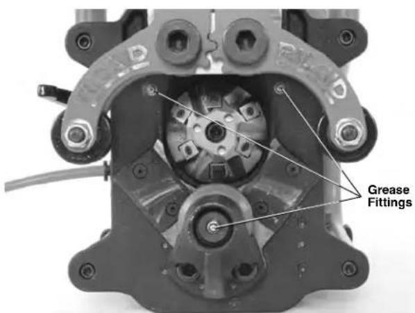
text_image
Grease FittingsFigure 23 – Grease Fittings
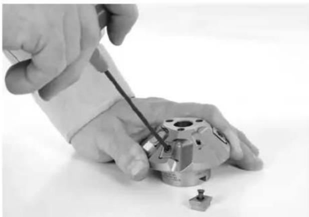
Rotating/Replacing Cutter Inserts
If the cutting edges are dull, worn or chipped, cutter inserts will need to be rotated or changed. Increased cutting time is an indication of cutter insert wear. Use care when handling inserts. Do not allow the inserts to touch each other or any other hard surface, they can be chipped or damaged.
-
With the cord unplugged, open the swing arms using the clamp screw. Inserts can be rotated/replaced with cutter head on the beveller.
-
Using the supplied T15 insert wrench, remove the screws and inserts from the cutter head. If needed, use the spanner wrench to turn the cutter head (Figure 24, 25A).
-
Inspect the insert mounting pockets and the insert screws for damage. Do not use damaged parts. Make sure mounting pockets are clean and free of debris.
-
Either install a new set of inserts or rotate the existing inserts (cutter inserts have 4 cutting edges) to expose an unused cutting edge in the cutting position. Do not mix new and used cutting edges – all cutting edges should be changed at the same time. Only use RIDGID inserts and insert screws. Other inserts or screws may cause injury or tool damage. Place a small amount of anti-seize grease on the screw and reinstall. Securely tighten the screw with the supplied wrench. Do not over tighten. When inserts are changed, you may notice a slight amount of vapor or smoke during the first few bevels. This is not a cause for concern.
natural_image
Close-up of hands using a screwdriver to adjust a mechanical component (no text or symbols visible)Figure 24 – Replacing Cutter Inserts
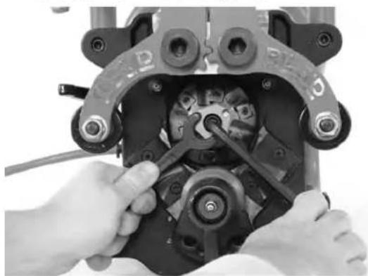
Changing Cutter Head
Cutter Heads need to be changed for different bevel angles. Only use the RIDGID cutter heads made for the beveller, Other cutter heads may cause injury or tool damage.
-
With the cord unplugged, open the swing arms using the clamp screw. Insert the provided spanner wrench in the holes on the end of the cutter head to prevent rotation.
-
Using a ^5/_16 " hex wrench, remove the socket head cap screw that holds the Cutter Head in place (Figure 25A).
-
Carefully remove the cutter head. Watch for sharp edges.
-
Inspect mounting area and cutter head for damage or debris. Do not use damaged parts.
- When replacing the cutter head, make sure it sits squarely on the spindle, with the slots in the cutter head engaging the drive pins (Figure 25B). Securely tighten socket head cap screw using the hex wrench and spanner wrench supplied.
natural_image
Close-up of hands assembling a mechanical component with no visible text or symbolsFigure 25A – Changing Cutter Heads
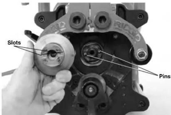
text_image
Slots PinsFigure 25B – Replacing Cutter Heads
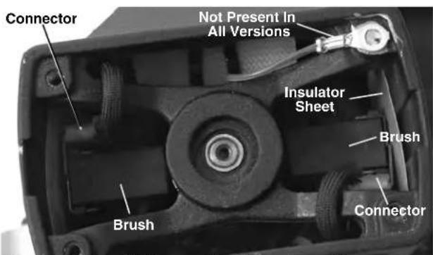
Replacing Carbon Brushes
Check the motor brushes every six months and replace when worn to less than l/2 (13 mm).
- To access the motor, remove the 4 bolts holding the frame to the face plate and remove the frame (Figure 1).
- Remove four screws holding the motor cover and remove cover.
- Using a pair of pliers, pull the motor brush housings straight out. Disconnect the electrical connector. (See Figure 26.)
text_image
Connector Not Present In All Versions Insulator Sheet Brush Brush ConnectorFigure 26 - Brush Placement - Motor Cover Removed
4a. Inspect brushes if less than 12 " (13 mm) long, replace brushes as a set.
b. Inspect the commutator for wear. If excessively worn, have tool serviced.
-
Depress the brush into the holder and insert into the motor housing. Firmly push down on brush housing and make sure it snaps in place. Inspect to make sure insulator sheets are properly positioned between brush holder and housing. Attach the connector and replace the motor cover.
-
Securely install the frame to the beveller.
Breaker
The beveller is equipped with a breaker (Figure 1) that will trip with excessive current draw. If this should happen, unplug the beveller. Using the instructions, remove the beveller from the work piece and inspect for the beveller for damage. If undamaged, press the breaker button to reset. If the breaker will not reset, allow beveller to cool for 15 minutes. Resume process starting with Inspection.
Wear Plates
If wear plates wear more than 0.03" (0.8 mm), replace.
Gib Plate Adjustment
If experiencing excessive vibration or tracking issues, the gib plate may need to be adjusted. To adjust:
- Loosen the gib screw.
- Place the cutter feed screw approximately at the middle of its travel.
- Loosen the gib plate jam nuts with a/8" wrench.
- Using a ^5/32 " hex key, tighten the gib plate set screws equally (same number of turns) until tight. Loosen each set screw ^1/2 turn.
-
While holding set screws in place with the hex key, tighten the jam nuts (Figure 27).
-
Lubricate the gib plates and cycle the cutter feed screw through its range several times. The parts should move smoothly with no looseness or binding. If needed repeat the adjustment process.
natural_image
Close-up of hands using a wrench to adjust mechanical components (no visible text or symbols)Figure 27 – Gib Plate Adjustment
Optional Equipment
WARNING
To reduce the risk of serious injury, only use equipment specifically designed and recommended for use with the RIDGID Model B-500 Transportable Pipe Beveller, such as those listed below.
| CatalogNo. Description |
| 48863 37 12^ Cutter Head |
| 48858 30° Cutter Head |
| 48868 45° Cutter Head |
| 48873 Pack Of 6 Cutter Inserts |
| 48883 Anti-Seize Grease – 1 Tube |
| 48888 Torx Wrench T15/S7 |
| 48893 Spanner Wrench |
| 48898 5/16" Hex Wrench |
| 55023 Model TBM-36 Adapter |
Further information on accessories specific to this tool can be found in the RIDGID catalog and online at RIDGID.com and RIDGID.eu
Machine Storage
WARNING The Model B-500 Transportable Beveller must be kept indoors or well covered in rainy weather. Store the machine in a locked area that is out of reach of children and people unfamiliar with bevellers. This machine can cause serious injury in the hands of untrained users.
Service And Repair
WARNING
Improper service or repair can make machine unsafe to operate.
The “Maintenance Instructions” will take care of most of the service needs of this machine. Any problems not addressed by this section should only be handled by an authorized RIDGID service technician.
Tool should be taken to a RIDGID Authorized Independent Service Center or returned to the factory. Only use RIDGID service parts.
For information on your nearest RIDGID Authorized Independent Service Center or any service or repair questions:
- Contact your local RIDGID distributor.
- Visit RIDGID.com to find your local RIDGID contact point.
- Contact Ridge Tool Technical Service Department at rttechservices@emerson.com, or in the U.S. and Canada call (800) 519-3456.
Disposal
Parts of the Model B-500 Beveller contain valuable materials and can be recycled. There are companies that specialize in recycling that may be found locally. Dispose of the components in compliance with all applicable regulations. Contact your local waste management authority for more information.

For EC Countries: Do not dispose of electrical equipment with household waste!
According to the European Guideline 2012/ - 19/ EU for Waste Electrical and Electronic Equipment and its implementation into national legislation, electrical equipment that is no
longer usable must be collected separately and disposed of in an environmentally correct manner.
natural_image
Mechanical device with RIDGID branding and cable, no visible text or symbols on main body
AVERTISSEMENT
Capacité ....Minimum – tuyau IPS ∅ 4" Maximum – tôle plate
Epaisseur paroi
natural_image
Black RIOGIO tool kit with multiple tools including wrench, pliers, and screwdriver (no visible text or labels)Figure 3 – Equipements de base
Icônes

text_image
RIDGID® Ridge Tool Company, Elyria, Ohio, U.S.A. Model No. B-500 Serial No. EBY 01586(0515) Volts 115 ~ 50/60 Hz Amps 13.0 no 950 /mintext_image
Vertical HorizontalFigure 6 – Orientations de tuyau acceptables(√) et inacceptables (✗)
Figure 9 – Securing Beveller to Adapter
natural_image
Technical illustration of a tripod-mounted surveying instrument with labeled component (Figure 11), no readable text or symbols beyond labelFigure 12 – Machine fixe, tuyau court, un porte-tubes
natural_image
Technical illustration of a mounted machine with tripod and two standers, labeled as Figure 11 (no text or symbols on the device itself)Figure 13 – Machine fixe, tuyau de grande longueur, porte-tubes multiples
natural_image
Industrial machine component with visible wiring and mounting bracket (no readable text or symbols)natural_image
Man in checkered shirt using a handheld device to measure a cylindrical object (no visible text or symbols)natural_image
Man operating industrial machinery with a tool, no visible text or symbolsnatural_image
Man operating a large industrial machine with pipes and a cylindrical pipe (no visible text or symbols)natural_image
Man in checkered shirt and gloves operating a large cylindrical device with mechanical arms (no visible text or symbols)natural_image
Man operating a large cylindrical device mounted on a tripod, no visible text or symbolsFigure 20C – Biseautage en cours (machine fixe/tuyau mobile)

natural_image
Close-up of a mechanical device with visible components and a 'RIDGID' logo on the side (no readable text beyond branding)Témoins lumineux
natural_image
Close-up of a mechanical component with threaded shaft and mounting holes (no visible text or symbols)natural_image
Close-up of hands using a screwdriver to adjust a mechanical component (no visible text or symbols)natural_image
Close-up of hands assembling a mechanical component with a wrench tool (no visible text or symbols)text_image
Orifices Brochesnatural_image
Close-up of hands using a wrench to adjust mechanical components (no visible text or symbols)Figure 27 – Réglage de la clavette
Accessoires
AVERTISSEMENT
natural_image
Mechanical device with RIDGID branding and attached cable, no visible text or symbols on the main body.
ADVERTENCIA
natural_image
Black RIDG ID tool kit with multiple tools including a wrench, pliers, and a handle (no visible text or labels)text_image
RIDGID® Ridge Tool Company, Elyria, Ohio, U.S.A. Model No. B-500 Serial No. EBY 01586 (0515) Volts 115 ~ 50/60 Hz Amps 13.0 n₀ 950 /mintext_image
Vertical Horizontalnatural_image
Mechanical device with visible wiring and a label 'RIDSID' on its body (no readable text beyond branding)natural_image
Man in checkered shirt and gloves handling equipment, no visible text or symbolsnatural_image
Man operating a large industrial machine with visible wiring and components (no text or symbols)natural_image
Man operating a large industrial machine with pipes and valves (no visible text or symbols)natural_image
Man in checkered shirt and gloves operating a large cylindrical mechanical device (no visible text or symbols)natural_image
Man operating a large industrial machine on a tripod (no visible text or symbols)natural_image
Close-up of a mechanical component with threaded shaft and mounting holes (no visible text or symbols)Figura 22 – Superficie moleteada del rodillo de mando, limpia
Lubricación
natural_image
Close-up of hands using a screwdriver to adjust a mechanical component (no visible text or symbols)natural_image
Close-up of hands assembling a mechanical component with no visible text or symbolsnatural_image
Close-up of hands using a wrench to adjust mechanical components (no visible text or symbols)Elyria, Ohio 44035-6001
U.S.A.
Ridge Tool Europe NV (RIDGID)
Schurhovenveld 4820
3800 Sint-Truiden
Belgium
EC DECLARATION OF CONFORMITY
We declare that the machines listed above, when used in accordance with the operator's manual, meet the relevant requirements of the Directives and Standards listed below.
DÉCLARATION DE CONFORMITÉ CE
DEKLARACJA ZGODNOŚCI WE
Conforms to ANSI/UL STD. 62841-1
Certified to CSA 22.2 #62841-1

Signature

Qualification: V.P. Engineering
Date: 09/01/2018
What is covered
RIDGID ^® tools are warranted to be free of defects in workmanship and material.
How long coverage lasts
This warranty lasts for the lifetime of the RIDGID tool. Warranty coverage ends when the product becomes unusable for reasons other than defects in workmanship or material.
How you can get service
To obtain the benefit of this warranty, deliver via prepaid transportation the complete product to RIDGE TOOL COMPANY, Elyria, Ohio, or any RIDGIDAAUTHORIZED INDEPENDENT SERVICE CENTER. Pipe wrenches and other hand tools should be returned to the place of purchase.
What we will do to correct problems
Warranted products will be repaired or replaced, at RIDGE TOOL'S option, and returned at no charge; or, if after three attempts to repair or replace during the warranty period the product is still defective, you can elect to receive a full refund of your purchase price.
What is not covered
Failures due to misuse, abuse or normal wear and tear are not covered by this warranty. RIDGE TOOL shall not be responsible for any incidental or consequential damages.
How local law relates to the warranty
Some states do not allow the exclusion or limitation of incidental or consequential damages, so the above limitation or exclusion may not apply to you. This warranty gives you specific rights, and you may also have other rights, which vary, from state to state, province to province, or country to country.
No other express warranty applies
This FULL LIFETIME WARRANTY is the sole and exclusive warranty for RIDGID ^® products. No employee, agent, dealer, or other person is authorized to alter this warranty or make any other warranty on behalf of the RIDGE TOOL COMPANY.

text_image
RIDGID FULL LIFETIME WARRANTY Against Material Defects & WorkmanshipParts are available online at Store.RIDGID.com
Ridge Tool Company
400 Clark Street
Elyria, Ohio 44035-6001
U.S.A.