HE205A1000 - Humidifier HONEYWELL - Free user manual and instructions
Find the device manual for free HE205A1000 HONEYWELL in PDF.

User questions about HE205A1000 HONEYWELL
0 question about this device. Answer the ones you know or ask your own.
Ask a new question about this device
Download the instructions for your Humidifier in PDF format for free! Find your manual HE205A1000 - HONEYWELL and take your electronic device back in hand. On this page are published all the documents necessary for the use of your device. HE205A1000 by HONEYWELL.
USER MANUAL HE205A1000 HONEYWELL
HE105, HE205 Whole Home Bypass Humidifier
INSTALLATION INSTRUCTIONS
natural_image
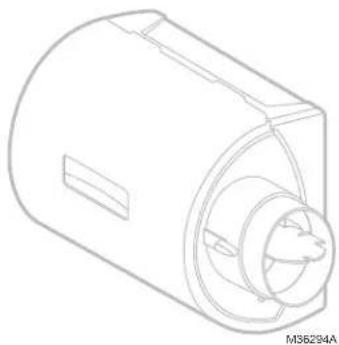
Technical line drawing of a cylindrical mechanical component with internal cavities and a slot (no text or symbols)APPLICATION
This kit contains your new HE105 or HE205 Humidifier, H6062 Digital Humidity Control and all the accessories required for installation.
How Your Humidifier Works
Your humidifier uses the principle that vapor (evaporated water) is created when warm air blows over a water-soaked area. As the vapor circulates, the relative humidity rises.
Your humidity control monitors the relative humidity and activates the humidifier accordingly. The humidifier has a water supply that dispenses water evenly over a humidifier pad. The warm dry air from the furnace passes over the humidifier pad and picks up the moist air to circulate it throughout your home.
Humidified air feels warmer and more comfortable so you may be able to lower your thermostat heating setpoint, which saves money on your heating fuel bills. The end result is that your humidifier gives you a comfortable environment that is also energy efficient.
Need Help?
For assistance with this product please visit http://honeywellhome.com or call Customer Care toll-free at 1-800-468-1502.
PREPARING FOR THE INSTALLATION
Be sure to identify all the required (Table 1) accessories (included) and make sure the appropriate tools are available before beginning the installation.
Included in the box:
- Humidifier
• H6062 Digital Humidity Control - Transformer
Canadian "C" models also include:
- 6 in. dia. bypass ducting (24 in.)
• 18 gauge thermostat wire (20 ft.)
• 1/4 in. (6.35 mm) OD feed water tubing (20 ft.) - 1/2 in. (12.7 mm) ID drain tubing (10 ft.)
- Saddle valve
Required Tools
Tools required for installation include:
• T i n s n i p
- Screwdriver
- Pliers
- Adjustable or open-end wrench
- Drill
- Level
• 3/4 in. (19 mm) sheet metal drill bit
SPECIFICATIONS
Model specific specifications are shown in Table 1.
Operating Ambient Temperature: 41 to 113 °F (5 to 45 °C)
Power Supply: 24 VAC / 60 Hz.
Power Consumption: 7 Watts with 24 Vrms
Water Pressure: 40 to 120 psi.
Orifice Output: .02 in. (0.5 mm)
Flow Rate at Nozzle: 4.7 GPH (18 L/hr.) under 120 psi
Table 1. Specifications.
| Model | Sizelength × width × depth | Duct OpeningH × W Pad Size | EvaporationOutput | |
| HE105 | 15.16 × 16.57 × 9.47 in.(385 × 421 × 240 mm) | 9.43 × 9.28 in.(240 × 236 mm) | 10 × 9.5 × 1.5 in.(254 × 241 × 38.1 mm) | 12 GPD |
| HE205 | 18.30 × 17.11 × 9.59 in.(465 × 434 × 243 mm) | 12.63 × 9.68 in.(321 × 246 mm) | 13.125 × 10 × 1.5 in.(333 × 254 × 38.1 mm) | 17 GPD |
Safety Definitions
These safety terms identify information you must read prior to installing or operating the humidifier.

WARNING
Indicates a hazardous situation which, if not avoided, could result in death or serious injury.

CAUTION
Indicates a hazardous situation which, if not avoided, could cause bodily injury or property damage.
Safety Precautions
Make sure you read and understand the following safety hazards before installing, using, or working with the humidifier:

WARNING
Serious Personal Injury Hazard. Can cause electrical shock and injury from moving parts.
Disconnect power and shut off water supply before removing cover.

WARNING
Hazardous Voltage Can cause personal injury or equipment damage. Do not cut or drill into any air conditioning or electrical accessory.

CAUTION
Chemical Hazard. Can cause personal injury or equipment damage. Do not use any line connected to an air conditioner. Do not use gas line.

CAUTION
Temperature and Static Pressure Hazard. Can cause property or equipment damage.
Locate humidifier where ambient temperature is between 41 and 113 °F (5 to 45 °C). Do not install humidifier where freezing temperatures could occur.
Be sure supply plenum static pressure is no greater than 0.4 in. wc and water pressure is no greater than 120 psi.

CAUTION
Sharp Edges Installation Hazard. Can cause personal injury.
Wear gloves and safety glasses.
IMPORTANT
Read and save these instructions.
Determining Best Location for Humidifier
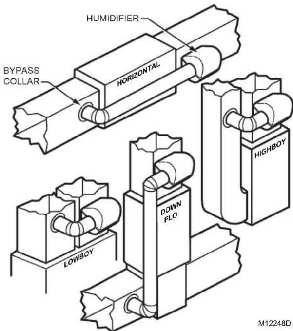
- Select a location for the humidifier on the supply (warm air stream) duct. See Fig. 1 for examples. Return duct mounting is acceptable if there are space restrictions on the supply duct. If you are mounting the humidifier on the return duct, simply swap "return duct" for "supply duct" throughout these instructions.
- Select a location that cannot damage the air conditioner A-coil during installation.
- Do not locate the humidifier on the furnace body.
- Mount the humidifier in a conditioned space to prevent freezing.
- Mount the humidifier at least 3 in. (78 mm) above the furnace body to allow adequate space for the solenoid valve and drain line.
text_image
HUMIDIFIER BYPASS COLLAR HORIZONTAL LOWBOY DOWN FLO HIGHBOY M12248DFig. 1. Typical humidifier installation locations.
text_image
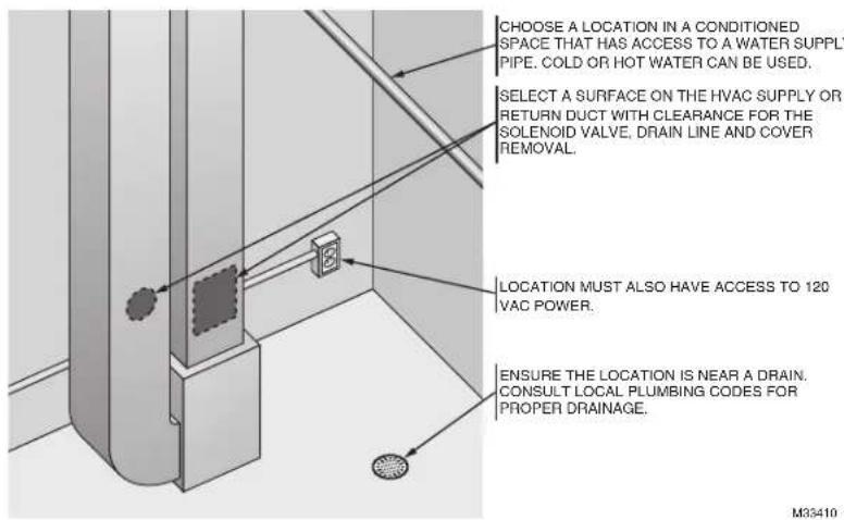
CHOOSE A LOCATION IN A CONDITIONED SPACE THAT HAS ACCESS TO A WATER SUPPLY PIPE. COLD OR HOT WATER CAN BE USED. SELECT A SURFACE ON THE HVAC SUPPLY OR RETURN DUCT WITH CLEARANCE FOR THE SOLENOID VALVE, DRAIN LINE AND COVER REMOVAL. LOCATION MUST ALSO HAVE ACCESS TO 120 VAC POWER. ENSURE THE LOCATION IS NEAR A DRAIN. CONSULT LOCAL PLUMBING CODES FOR PROPER DRAINAGE. M35410Fig. 2. Typical humidifier installation locations.
Selecting Location for Humidistat
- Select a location for the humidistat on the return plenum or on the wall in the living space.
- Mounting on the return plenum is the easiest installation for the control wiring circuit.
- Make sure that the thermostat wire is adequate to reach from the humidifier to the humidistat, and also from the humidifier to the transformer. See "Wiring" on page 5 for more information.
IMPORTANT
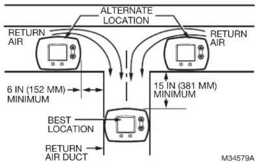
The humidistat must be mounted upstream from the humidifier or bypass duct to ensure it is properly sensing the relative humidity of the living space. Locate the control at least 8 in. (203 mm) upstream from the humidifier in the return air duct. (See Fig. 3.)
flowchart
graph TD
    A["RETURN AIR"] --> B["ALTERNATE LOCATION"]
    B --> C["RETURN AIR"]
    D["RETURN AIR"] --> E["ALTERNATE LOCATION"]
    E --> F["RETURN AIR"]
    G["6 IN (152 MM) MINIMUM"] <--> H["BEST LOCATION"]
    I["15 IN (381 MM) MINIMUM"] <--> J["RETURN AIR DUCT"]
    K["M34579A"] --> L["RETURN AIR DUCT"]
Fig. 3. Selecting duct location for humidistat.
INSTALLATION
- Turn off power to the air handling system at the circuit breaker.
- Draw a level line on the plenum in the selected location.
IMPORTANT
Be sure the mounting template is level before marking. Use of a small level is recommended.
- Locate the template (form number 33-00210, included in the box). For the HE105 model, cut out the template along the dotted line. For the HE205 model, use the entire sheet as a template.
- Tape the template in position and trace around the template.
- Remove the template and carefully cut the rectangular opening using tin snips.
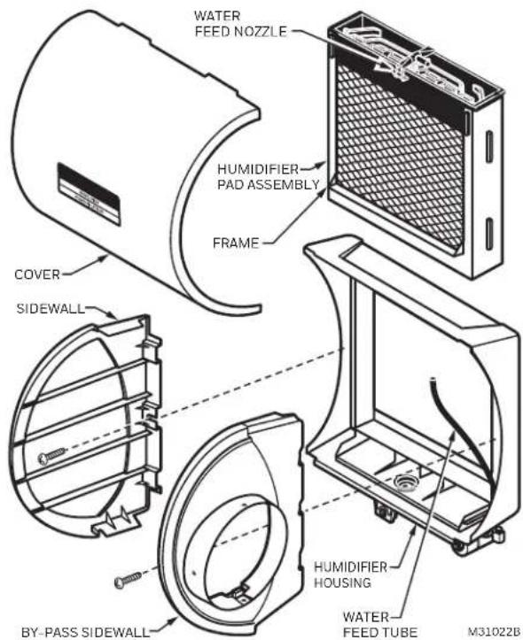
- Disassemble the humidifier; remove the cover and take out the humidifier pad assembly. See Fig. 4.
text_image
WATER FEED NOZZLE HUMIDIFIER PAD ASSEMBLY FRAME COVER SIDEWALL BY-PASS SIDEWALL HUMIDIFIER HOUSING WATER FEED TUBE M31022BFig. 4. Disassembling humidifier.
-
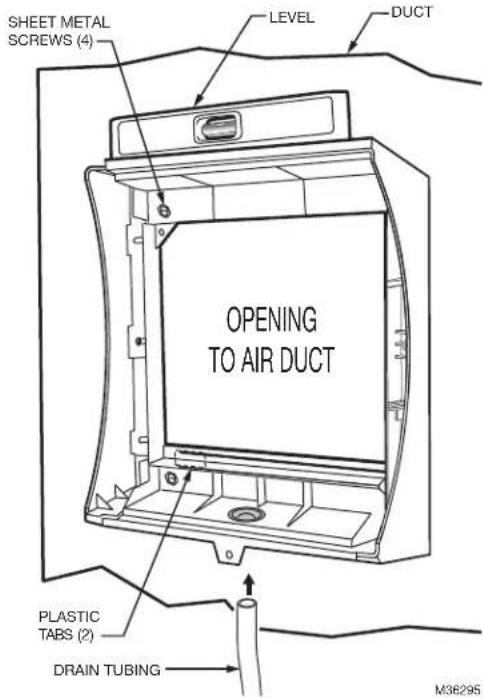
Make sure the humidifier housing is level, then position it in the opening so the plastic tabs are in place on the lower sheet metal edge of the opening. Use pliers, as necessary, to flatten cut edges. See Fig. 5.
-
Secure the humidifier housing to the opening at the top and bottom using sheet metal screws.
-
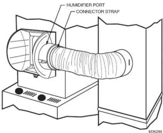
Reassemble humidifier side plates to customize the orientation for your specific install. The side plate with the humidifier port needs to be on the side of the humidifier that is closest to the bypass ducting. Be sure to open the bypass flap for use and close it when the humidifier is not used. See Fig. 6.
text_image
SHEET METAL SCREWS (4) LEVEL DUCT OPENING TO AIR DUCT PLASTIC TABS (2) DRAIN TUBING M36295Fig. 5. Installing humidifier on duct.
-
Slide bypass duct over the humidifier port on the HE105/HE205, making sure that the flex duct advances past the raised plastic tabs on the port. These tabs will help to hold the flex duct in place. Verify that the damper blade has adequate clearance to move back and forth between the closed and open positions. Secure the flex duct in place with the plastic connector strap.
-
Seal the duct connections with foil tape. Seal both 1) the connection between the starter collar end of the flex duct and the home's duct work and 2) the end of the flex duct to the humidifier over the top of the connector strap.
-
Reinstall the humidifier pad assembly in the humidifier housing.
-
Hinge the cover in place and secure with the thumb-screw located at the bottom of the cover.
text_image
HUMIDIFIER PORT CONNECTOR STRAP M36298Fig. 6. Connecting bypass ducting.
Connecting the Plumbing
-
Hot or cold water, either hard or softened, can be used in the humidifier. Cut the water line so it reaches from the humidifier to the main water supply tap.
-
Turn off water supply and tap into a water line.
-
Consult local codes for proper plumbing.
- Use an approved saddle valve or a T-fitting and manual shutoff valve to tap into the water line.
- Refer to the literature included with the valve you chose and the local plumbing codes. Use proper technique for the valve.
- Connect the other end of the humidifier water line to the water valve.
- Use 1/4 in. O.D. copper tubing and connect to inlet side of solenoid valve via a compression fitting or Quick Connect fitting.
- Place brass compression nut over copper tubing.
NOTE: Do not over tighten compression nut.
• Moderate tightness prevents leaking.
- Slide the brass ferrule over the tubing.
- Insert tubing into solenoid valve fitting and support the valve while tightening the compression nut.
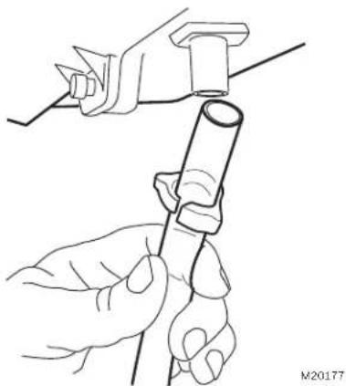
- Connect a water drain line.
- Consult and follow local plumbing codes for drain pipe size and flow requirement.
- The ideal installation is directly to the main floor drain using a rubber drain hose.
a. Slide a drain clamp over the tubing.
b. Push the tubing over the drain nipple on the humidifier.
c. Route the drain hose to the floor drain. The hose must have a continuous downward slope.
d. Direct the hose outlet into the floor drain. Secure the hose to reduce the risk of water pooling or splashing as it drains from the humidifier. See Fig. 7.
natural_image
Line drawing of hands holding a tool with a cylindrical component (no text or symbols)Fig. 7. Installing the drain tubing.
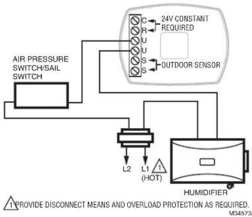
flowchart
graph TD
    A["AIR PRESSURE SWITCH/SAIL SWITCH"] --> B["24V CONSTANT REQUIRED"]
    B --> C["OUTDOOR SENSOR"]
    C --> D["HUMIDIFIER"]
    D --> E["L1 (HOT)"]
    E --> F["L2"]
    style A fill:#f9f,stroke:#333
    style B fill:#ccf,stroke:#333
    style C fill:#cfc,stroke:#333
    style D fill:#fcc,stroke:#333
    style E fill:#cff,stroke:#333
    note right of E: "PROVIDE DISCONNECT MEANS AND OVERLOAD PROTECTION AS REQUIRED."
Fig. 9. Wiring HumidiPRO in line with air proving device.
WIRING

CAUTION
Hazardous Voltage.
Can cause personal injury or equipment damage.
Disconnect power supply before installing or servicing equipment.
IMPORTANT
All wiring must comply with applicable local code, ordinances and regulations.
Wire the humidifier, humidistat and transformer. See
Fig. 8-11.
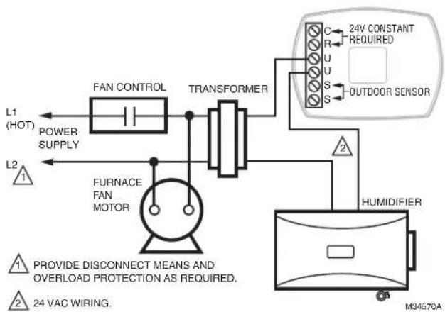
flowchart
graph TD
    L1["(HOT)"] --> POWER["SUPPLY"]
    L2["1"] --> F["FURNACE FAN MOTOR"]
    F --> TRANSFORMER
    TRANSFORMER --> C["C"]
    TRANSFORMER --> R["R"]
    TRANSFORMER --> U["U"]
    TRANSFORMER --> S["S"]
    TRANSFORMER --> OUTDOOD["OUTDOOR SENSOR"]
    TRANSFORMER --> HUMIDIFIER
    HUMIDIFIER --> 24V["24V CONSTANT REQUIRED"]
    HUMIDIFIER --> M34570A["M34570A"]
    style L1 fill:#f9f,stroke:#333
    style L2 fill:#f9f,stroke:#333
    style F fill:#ccf,stroke:#333
    style TRANSFORMER fill:#cfc,stroke:#333
    style HUMIDIFIER fill:#fcc,stroke:#333
    note1["1 PROVIDE DISCONNECT MEANS AND OVERLOAD PROTECTION AS REQUIRED."]
    note2["24 VAC WIRING."]
Fig. 8. Wiring H6062 to humidifier with Fan Interlock.
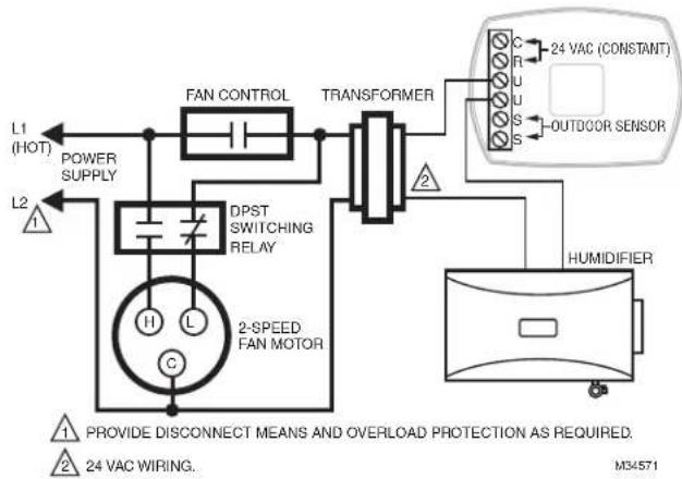
flowchart
graph TD
    L1["(HOT)"] --> POWER["SUPPLY"]
    L2["△"] --> POWER
    POWER --> DPST["DPST SWITCHING RELAY"]
    DPST --> 2SPEF["FAN MOTOR"]
    DPST --> FAN_CONTROL["FAN CONTROL"]
    FAN_CONTROL --> TRANSFORMER["TRANSFORMER"]
    TRANSFORMER --> OUTDOOR["OUTDOOR SENSOR"]
    OUTDOOR --> HUMIDIFIER["HUMIDIFIER"]
    HUMIDIFIER --> 2SPEF
    style 2SPEF fill:#f9f,stroke:#333
    note right of 1: Provide disconnect means and overload protection as required.
        24 VAC WIRING.
        M34571
Fig. 10. Wiring HumidiPRO with 2-speed fan motor.*
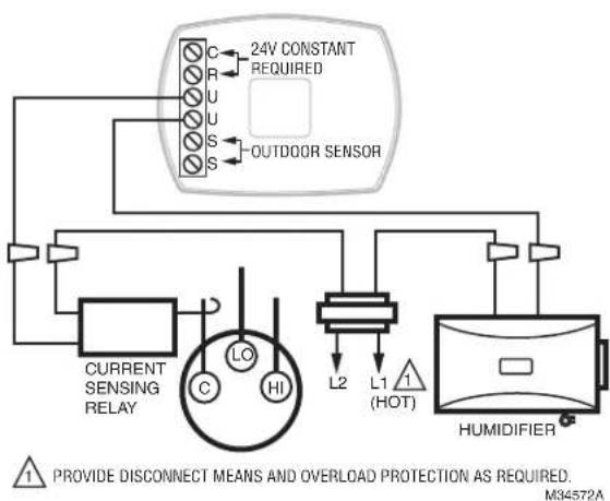
flowchart
graph TD
    A["24V CONSTANT REQUIRED"] --> B["OUTDOOR SENSOR"]
    B --> C["C"]
    B --> D["R"]
    B --> E["U"]
    B --> F["S"]
    B --> G["L2"]
    B --> H["L1 (HOT)"]
    B --> I["HUMIDIFIER"]
    C --> J["Current Sensing Relay"]
    D --> J
    E --> J
    F --> J
    G --> J
    H --> J
    I --> J
    J --> K["LO"]
    J --> L["HI"]
    style A fill:#f9f,stroke:#333
    style B fill:#ccf,stroke:#333
    style C fill:#cfc,stroke:#333
    style D fill:#fcc,stroke:#333
    style E fill:#cff,stroke:#333
    style F fill:#ffc,stroke:#333
    style G fill:#fcc,stroke:#333
    style H fill:#ffc,stroke:#333
    style I fill:#fcc,stroke:#333
Fig. 11. Wiring HumidiPRO with current-sensing relay.
* When a thermostat with IAQ control is used instead of a humidistat, it simplifies the wiring circuit. The thermostat U contacts are installed in place of the H6062 from Fig. 10 and the sail switch is removed from the circuit. No special wiring of the transformer primary, sail switch, or relay is needed.
☐ Humidifier is level.
☐ Control wiring was reviewed using circuit diagram.
☐ Humidifier is plugged in.
□ Feed line has no kinks.
☐ Drain line slopes continuously down and ends at floor drain.
☐ Water hose inside humidifier is connected to PerfectFlow™ water distribution tray.
After installation use the following steps to check the humidifier operation:
- Turn on the power and the water supply.
- Turn the H6062 Humidistat all the way up and turn on the heat by setting the thermostat to 10^ F ( 6^ C) above room temperature.
IMPORTANT
The furnace blower must be on to activate the humidifier.
- Make sure that water is flowing out of the drain hose. If water does not flow, see Troubleshooting Your Humidifier section.
- Check for leaks.
- Reset the thermostat and H6062 Humidistat to a comfortable setting for automatic operation.
OPERATION
How Your Humidifier Works
Your humidifier uses the principle that vapor (evaporated water) is created when warm air blows over a watersoaked area. As the vapor circulates, the relative humidity rises.
Your humidity control monitors the relative humidity and activates the humidifier accordingly. The humidifier has a water supply that dispenses water evenly over a humidifier pad. The warm dry air, from the furnace, passes over the humidifier pad and picks up the moist air to circulate it throughout your home.
Humidified air feels warmer and more comfortable so you may be able to lower your thermostat heating setpoint, which saves money on your heating fuel bills. The end result is that your humidifier gives you a comfortable environment that is also energy efficient.
Controlling Your Humidity Settings
Your H6062 Humidistat controls your humidifier.
- Choose the humidity control setting using the combination of relative humidity/outdoor temperature setting scale on your humidity control dial.
- When the outdoor sensor is used, the H6062 will optimize the humidity level while reducing moisture condensation on the windows. See the H6062 instructions for settings and adjustments.
NOTE: If the outdoor sensor is not used with H6062, as the outside temperature drops, a lower humidity setting is recommended to accommodate dew-point effects. These settings should reduce the accumulation of moisture and ice on windows and other areas of the home.
- Adjust the humidity control setting to adjust for indoor activities such as cooking, showering and clothes drying, which can cause excessive levels of humidity that can accumulate moisture on your windows.
NOTE: If these activities persist for more than a few hours, set the humidity control to the lowest setting to turn off the humidifier. If the condition does not improve, ventilate your home to remove the moisture.
Table 2. Setting Your Humidistat when outdoor sensor is
| When Outside Temperature is: | Use This Control Setting: |
| -20 °F (-29 °C) 15 | |
| -10 °F (-23 °C) 20 | |
| 0 °F (-18 °C) 25 | |
| +10 °F (-12 °C) 30 | |
| +20 °F (-7 °C) 35 | |
| Above 20 °F (-7 °C) 40 |
not used.
MAINTAINING YOUR HUMIDIFIER
A regular maintenance program prolongs the life of your humidifier and makes your home more comfortable. The frequency of cleaning depends on the condition of your water.
You can use either hard or soft water in your humidifier, but hard water mineral deposits are more difficult to clean than soft water deposits.
IMPORTANT
Never oil any part of the humidifier.
End of Humidification Season
- Clean the humidifier and shut it off at the end of the heating season.
- Turn the water off at the saddle valve or T-valve fitting by turning the handle to the right (clockwise) until the water stops flowing and/or there is resistance.
- Un-power the humidifier.
- Turn the damper blade to the "closed" position.
Replacement Humidifier Pads
Resideo recommends replacing the humidifier pad on an annual basis. However, if your home has hard water, the pad may need to be replaced more frequently because of the buildup of minerals diminishing its ability to operate normally. If there is access to a water softener, it is recommended to use softened water.
Table 3. Replacement pad part numbers.
| Model Replacement Pad | |
| HE105 HC22 | |
| HE205 HC26 | |
Checkout
- Open the water supply and bypass duct flap.
NOTE: The furnace blower must be on for the humidifier to operate.
- Set the thermostat setpoint 10^ F ( 6^ C) above the room temperature.
- Set the Humidity Control to a high humidity setting, or place the setting in the test position.
- Observe the water running out of the drain line to be sure the humidifier is working properly.
- Check for leaks.
- Reset the Humidity Control to a comfortable setting, or the Automatic Humidity Control to the desired frost factor setting.
TROUBLESHOOTING YOUR HUMIDIFIER
| Problem What to look for What to do | ||
| Water leakage | Leaking joints. Shut off water and tighten connections. | |
| Brass tubing inserts Verify that brass tubing inserts are used. | ||
| Saddle valve leaking. Verify rubber pad is installed on saddle valve. | ||
| No water to drain. | Electrical Verify control circuit wiring.Check all connections. | |
| Humidistat Turn humidistat up and down and listen for contact to click. | ||
| Humidifier power Verify that outlet has power. | ||
| Solenoid | After verifying other wiring components, turn on furnace fan, turn humidistat up and down, and listen for solenoid to click. | |
| Plumbing | Verify plumbing connections.Check for kinks. | |
| Saddle valve | Verify that needle pierces water line and then backs out needle to open valve. | |
| Humidifier | Remove cover and verify that water flows into distribution tray. | |
| Drain tubing | Verify no obstructions. | |
| Air leakage | Check duct joints | Seal with foil tape. |
| Low humidity | Furnace blower not operating. | Reset circuit breaker or check for blown fuse.Check that the furnace power is on.Check all external wiring connections.Check the humidity control setting.Call a professional heating contractor. |
| Rapid air changes.Drafts (cold air is dry and is an added load to the humidifier). | Keep doors and windows closed.Close fireplace damper when not in use.Keep exhaust fan running time to a minimum.Seal around doors and windows. | |
| Damper in “closed” position | Set damper blade to "open" position to allow humidification. | |
| High humidity | Condensation on walls. | Turn off humidity control and water until condensation is completely evaporated. |
| Heavy condensation on windows. | Turn humidity control down low enough to eliminate condensation caused by moisture from bathing, mopping, cooking, etc. If moisture persists, more ventilation is needed. | |
REPLACEMENT PARTS
Refer to Fig. 12 and Table 4 when ordering replacement parts.
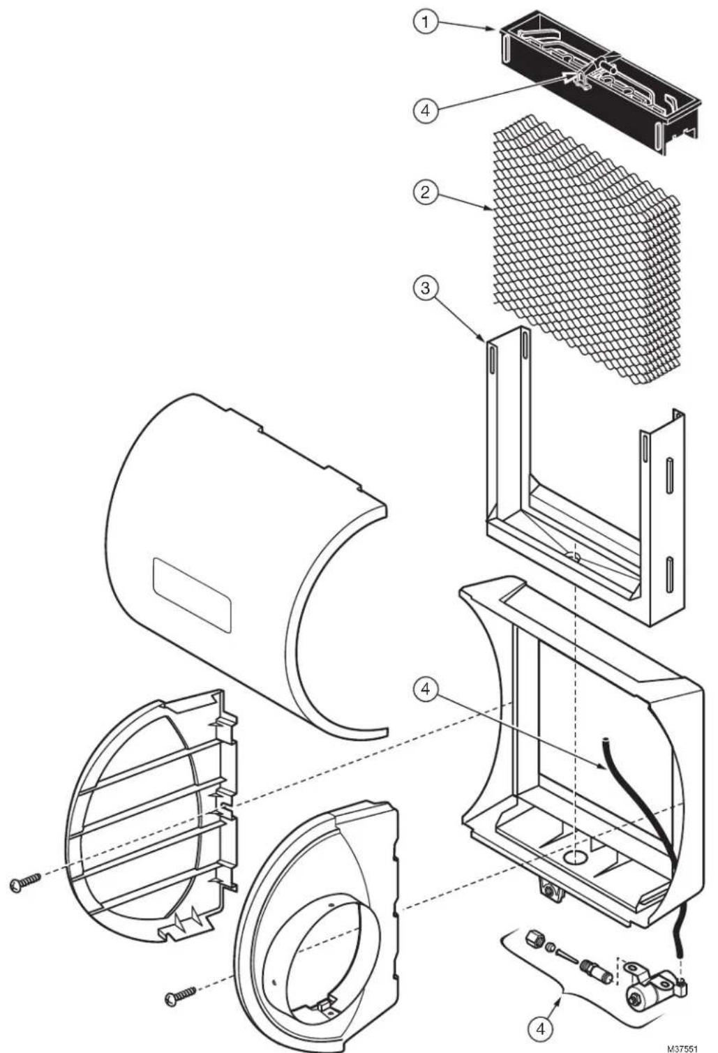
text_image
Exploded view diagram of a refrigerator with numbered parts for assembly or maintenance reference.Fig. 12. Exploded view of humidifier parts.
Table 4. List of replacement parts for HE105, HE205.
| Exploded View Number(see Fig. 12) Description HE105 HE205 | |||
| 1 PerfectFloTM water distribution tray 32001619-001/U 32001630-001/U | |||
| 2 | Humidifier Pad Standard HC22A1007/U HC26A1008/U | ||
| Humidifier Pad with AgION Coating HC22E1003/U HC26E1004/U | |||
| 3 Frame 32001621-001/U 32001632-001/U | |||
| 4 Solenoid valve assembly(includes water feed tube and nozzle) | 32001639-002/U 32001639-002/U | ||
| – Hardware Kit for Solenoid Assembly (same as solenoid valve assembly without the solenoid valve) | 32001752-001 32001752-001 | ||
| – Current Sensing Relay | 32001754-001 32001754-001 | ||
5-YEAR LIMITED WARRANTY
Resideo warrants this product, excluding battery, to be free from defects in workmanship or materials, under normal use and service, for a period of five (5) years from the date of first purchase by the original purchaser. If at any time during the warranty period the product is determined to be defective due to workmanship or materials, Resideo shall repair or replace it (at Resideo's option).
If the product is defective,
(i) return it, with a bill of sale or other dated proof of purchase, to the place from which you purchased it; or
(ii) call Resideo Customer Care at 1-800-468-1502. Customer Care will make the determination whether the product should be returned to the following address: Resideo Return Goods, 1985 Douglas Dr. N., Golden Valley, MN 55422, or whether a replacement product can be sent to you.
This warranty does not cover removal or reinstallation costs. This warranty shall not apply if it is shown by Resideo that the defect was caused by damage which occurred while the product was in the possession of a consumer.
Resideo's sole responsibility shall be to repair or replace the product within the terms stated above. RESIDEO SHALL NOT BE LIABLE FOR ANY LOSS OR DAMAGE OF ANY KIND, INCLUDING ANY INCIDENTAL OR CONSEQUENTIAL DAMAGES RESULTING, DIRECTLY OR INDIRECTLY, FROM ANY BREACH OF ANY WARRANTY, EXPRESS OR IMPLIED, OR ANY OTHER FAILURE OF THIS PRODUCT.
Some states do not allow the exclusion or limitation of incidental or consequential damages, so this limitation may not apply to you. THIS WARRANTY IS THE ONLY EXPRESS WARRANTY RESIDEO MAKES ON THIS PRODUCT. THE DURATION OF ANY IMPLIED WARRANTIES, INCLUDING THE WARRANTIES OF MERCHANTABILITY AND FITNESS FOR A PARTICULAR PURPOSE, IS HEREBY LIMITED TO THE FIVE YEAR DURATION OF THIS WARRANTY. Some states do not allow limitations on how long an implied warranty lasts, so the above limitation may not apply to you.
This warranty gives you specific legal rights, and you may have other rights which vary from state to state. If you have any questions concerning this warranty, please write Resideo Customer Care, 1985 Douglas Dr, Golden Valley, MN 55422 or call 1-800-468-1502.

resideo
www.resideo.com
Resideo Technologies, Inc.
1985 Douglas Drive North, Golden Valley, MN 55422
1-800-468-1502
33-00229EF-05 M.S. Rev. 07-22 | Printed in United States
© 2022 Resideo Technologies, Inc. All rights reserved.
The Honeywell Home trademark is used under license from Honeywell International, Inc. This product is manufactured by Resideo Technologies, Inc. and its affiliates.
natural_image
Technical line drawing of a cylindrical mechanical component with internal cavities and mounting holes (no text or symbols)APPLICATION
natural_image
Line drawing of hands using a tool to adjust or install a cylindrical component (no text or symbols present)text_image
Exploded view diagram of a refrigerator with numbered parts for identification and assembly reference.Resideo Technologies, Inc.
1985 Douglas Drive North, Golden Valley, MN 55422
1-800-468-1502
© 2022 Resideo Technologies, Inc. All rights reserved.
The Honeywell Home trademark is used under license from Honeywell International, Inc. This product is manufactured by Resideo Technologies, Inc. and its affiliates.