CODIX 924 - Measuring equipment Kübler - Free user manual and instructions
Find the device manual for free CODIX 924 Kübler in PDF.
| Product type | Electronic preselect counter |
| Brand | Kübler |
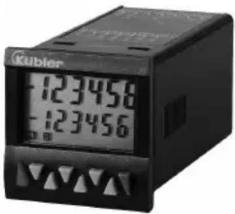
| Model | CODIX 924 |
| Dimensions (W x H x D) | 48 x 48 x 91 mm |
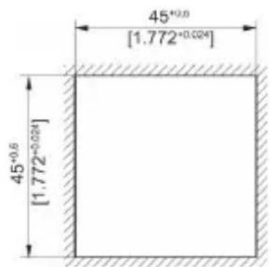
| Panel cut-out | 45 x 45 mm (+0.6 mm) |
| Weight | Approx. 125 g |
| Power supply | 100–240 VAC ±10% (50/60 Hz), 24 VAC ±10%, or 10–30 VDC |
| Power consumption | Max. 9.5 VA (AC) or 5 W (DC) |
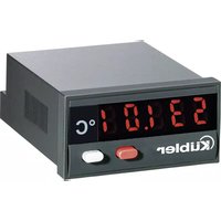
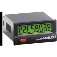
| Display | LCD 2 lines, 6 digits, positive or negative, optional backlight (green, red, red-green) |
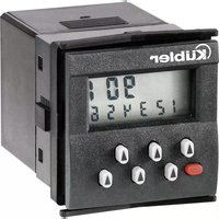
| Main functions | Pulse counting, tachometer/frequency meter, hour meter; two presets; relay or optocoupler outputs; programming via keys; teach function; prepositioning |
| Max. counting frequency | 55 kHz (pulses), 65 kHz (frequency meter) |
| Inputs | INP A, INP B (signal), RESET, GATE, LOC.INP, MPI; programmable NPN/PNP |
| Outputs | Output 1: NO relay contact or NPN optocoupler; Output 2: changeover relay or NPN optocoupler |
| Operating temperature | -20 °C to +65 °C |
| Protection rating | IP65 front panel |
| Maintenance and cleaning | Clean front panel with a soft damp cloth; no internal maintenance required |
| Safety | Protection class 2 (front panel); do not open; use external fuses; flush mounting |
| Repair | Return to manufacturer or supplier; opening prohibited |
Frequently Asked Questions - CODIX 924 Kübler
User questions about CODIX 924 Kübler
0 question about this device. Answer the ones you know or ask your own.
Ask a new question about this device
Download the instructions for your Measuring equipment in PDF format for free! Find your manual CODIX 924 - Kübler and take your electronic device back in hand. On this page are published all the documents necessary for the use of your device. CODIX 924 by Kübler.
USER MANUAL CODIX 924 Kübler
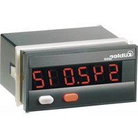
Electronic Preset Counter
With two presets
Models
LCD positive
LCD positive, green backlighting
LCD negative, red backlighting
LCD negative, red-green backlighting
Impulszähler: cnt.dir, up.dn, up.up, quad, quad2, quad4, A/B, (A-B)/Ax100%
Frequenzzähler: A, A-B, A+B, quad, A/B, (A-B)/Ax100%
Zeitzähler: FrErun, Auto, InpA.InpB, InpB.InpB
Add, Sub, AddAr, SubAr, AddBat, SubBat, AddTot, SubTot, Trail, TrailAr 4-stufiger RESET-Mode
text_image
Funcct Funcct CountMenü Grundfunktion
Add/Sub/Trail < 1 ms
4-30 VPegel Low: 0 ... 2VDC
High: 3,5 ... 30 VDC
SELV, CLASS II (Limited
Po w e r S c
| HTL | 5V | |
| A | 65 kHz | 9 kHz |
| A - BA + BA / B(A-B)/A | 65 kHz | 9 kHz |
| Quad | 30 kHz | 9 kHz |
4-30 V-Pegel Low: 0 .. 2VDC
High: 3,5 .. 30 VDC
Electronic Preset Counter
With two presets
Models
LCD positive
LCD positive, green backlighting
LCD negative, red backlighting
LCD negative, red-green
backlighting
Table of Contents
1 Preface 4
2 Safety instructions and Warnings 4
2.1 Use according to the intended purpose 4
2.2 Mounting in a control panel 4
2.3 Electrical Installation 5
2.4 Cleaning and maintenance 5
3 Description 6
4 Display/Operating elements 6
5 Inputs 6
5.1 INP A, INP B 6
5.2 RESET 6
5.3 GATE 6
5.4 LOCK INPUT 6
5.5 MPI 6
6 Outputs 7
6.1 Output 1 7
6.2 Output 2 7
6.3 Active Outputs 7
7 Programming 7
7.1 Entering the programming 7
7.2 Choice of main menus 7
7.3 Entering a Submenu 7
7.4 Selecting the menu items 7
7.5 Setting the menu items 7
7.6 Accepting the setting 7
7.7 Ending the programming 7
7.8 Programming Menu 8
7.8.1 Default parameters 8
7.8.2 Table: Parameter Sets 8
7.8.3 Setting the Basic Function 8
7.8.4 Pulse Counter 9
7.8.5 Tacho/Frequency meter 11
7.8.6 Timer 13
7.9 Setting the presets 17
7.9.1 Setting via Decade Keys 17
7.9.2 Setting with Teach-In Function 17
7.9.3 Setting the tracking presets (trail) 17
7.10 Set Function 17
8 Error message 17
9 Connections 18
9.1 Signal and Control Inputs 18
9.2 Supply voltage and Outputs 18
9.2.1 Version with relays 18
9.2.2 Version with Optocouplers 18
10 Technical Data 18
10.1 General Data 18
10.2 Pulse counter 18
10.3 Tacho/Frequency meter 18
10.4 Timer 19
10.5 Signal and Control inputs 19
10.6 Outputs 19
10.7 Supply voltage 19
10.8 Sensor supply voltage 19
10.9 Climatic Conditions 19
10.10 EMC 19
10.11 Device safety 20
10.12Mechanical Data 20
10.13Connections 20
11 Scope of Delivery 20
12 Ordering codes 20
13 Frequencies (typical) 20
13.1 Pulse counter 20
13.2 Frequency meter 21
14 Input modes: Pulse counting 22
15 Input modes: Timing 24
16 Input modes: Frequency meter 25
17 Output operations 26
18 Dimensional Drawings 28
1 P r e f a c e

Please read this instruction manual entirely and carefully before installation and start-up. Please observe all warnings and advice, both for your own safety and for general plant safety. If the device is not used in accordance with this instruction manual, then the intended protection can be impaired.
2 Safety instructions and Warnings

Please use the device only if its technical condition is perfect. It should be used only for its intended purpose. Please bear in mind safety aspects and potential dangers and adhere to the operating instructions at all times.
Defective or damaged devices should be disconnected from the mains immediately and taken out of operation. The device shall not be opened. Use the repair service of the manufacturer.
Only connect the device to the electricity networks provided to that purpose.
The safety of the system in which the device is integrated is the responsibility of the installer.
Disconnect all electricity networks prior to any installation or maintenance work.
Use exclusively cables approved in your country and designed for your temperature and power ranges. Installation and service work shall be carried out exclusively by qualified personnel.
The device must compulsorily be protected with approved external fuses. The value of these fuses can be found in the technical information.

This symbol is used on the device to remind of the existence of dangers, which are referred to in this manual.
2.1 Use according to the intended purpose
The preset counter detects and measures pulses, times and frequencies up to max. 60 kHz and offers a wide variety of different operating modes. At the same time, the preset counter processes programmed presets. Use for any purpose over and beyond this will be deemed as not in accordance with its intended purpose and thus not complying with the requirements.
The application area for this device lies in industrial processes and controls, in the fields of manufacturing lines for the metal, wood, plastics, paper, glass, textile and other like industries. Over-voltages at the terminals of the device must be kept within the limits of Over-voltage Category II.
The device must only be operated when mounted in a panel in the correct way and in accordance with the section "Technical Data".
The device is not suitable for use in hazardous areas and for areas excluded in EN 61010 Part 1. If the device is used to monitor machines or processes in which, in the event of a failure of the device or an error made by the operator, there might be the risk of damaging the machine or causing an accident to the operators, it is your responsibility to take the appropriate safety measures.
The device has been designed for indoor operation. It may nevertheless be used outdoors, provided the technical data is adhered to. In this case, take care to provide suitable UV protection.
2.2 Mounting in a control panel

CAUTION
Mount the device away from heat sources and avoid direct contact with corrosive liquids, hot steam or similar.
Provide a free space of 10mm all around the device for its ventilation.
The device should be mounted so that the terminals are out of the reach of the operator and cannot be touched by him. When mounting the device, consider the fact that only the front side is classified as accessible for the operator.
Mounting instructions
- Remove the mounting clip from the device.
- Insert the device from the front into the panel cut-out, ensuring the front-panel gasket is correctly seated.
- Slide the fixing clip from the rear onto the housing, until the spring clamps are under tension and the upper and lower latching lugs have snapped into place.
Note: In case of proper installation, IP65 can be reached on the front side.
2.3 Electr

DANGER
The device must be disconnected from any power supply prior to any installation or maintenance work. Make sure that no more voltages LIABLE TO CAUSE AN ELECTROCUTION are present.
AC-powered devices must only be connected to the low-voltage network via a switch or circuit breaker installed close to the device and marked as their disconnecting device.
Installation or maintenance work must only be carried out by qualified personnel and in compliance with the applicable national and international standards.
Take care to separate all extra-low voltages entering or exiting the device from hazardous electrical conductors by means of a double or reinforced insulation (SELV circuits).

DANGER
The device must be protected externally for its proper operation. Information about the prescribed fuses can be found in the technical information.
The relay outputs are not protected internally in the device. Without suitable protection of the relay outputs, undesired heat development or even fire may occur. The relay outputs must be protected externally by the manufacturer of the plant. It must also be made sure that, even in case of a malfunction, the values stated in the technical data are under no circumstances exceeded.
- During installation, make sure that the supply voltage and the wiring of the output contacts are both fed from the same mains phase, in order not to exceed the maximum permitted voltage of 250V.
- The cables and their insulation must be designed for the planned temperature and voltage ranges. Regarding the type of the cables, adhere to the applicable standards of the country and of the plant. The cross sections allowed for the screw terminals can be found in the technical data.
- Before starting the device, check the cables for proper wiring and tightening. The screws of
i unused screw terminals must be screwed to the stop, so that they cannot loosen and get lost.
- The device has been designed for overvoltage category II. If higher transient voltages cannot be excluded, additional protection measures must be taken in order to limit the overvoltage to the values of CAT II.
Advice on noise immunity
All connections are protected against external sources of interference. The installation location should be chosen so that inductive or capacitive interference does not affect the device or its connecting lines! Interference (e.g. from switch-mode power supplies, motors, clocked controllers or contactors) can be reduced by means of appropriate cable routing and wiring.
Measures to be taken:
- Use only shielded cable and control lines. Connect shield at both ends. The conductor cross-section of the cables should be a minimum of 0.14 mm ^2 .
- The shield connection to the equipotential bonding should be as short as possible and with a contact area as large as possible (low-impedance).
- Only connect the shields to the control panel, if the latter is also earthed.
- Install the device as far away as possible from noise-containing cables.
- Avoid routing signal or control cables parallel to power lines.
2.4 C l e a n i n
The front side of the unit should only be cleaned using a soft damp (water!) cloth. Cleaning of the embedded rear side is not planned and is the responsibility of the service personnel or of the installer.
In normal operation, this device is maintenance-free. Should the device nevertheless not operate properly, it must be sent back to the manufacturer or to the supplier. Opening and repairing the device by the user is not allowed and can adversely affect the original protection level.
3 Description
6-digit multifunction LCD display
Easy-to-read 2-line LCD-display with annunciators for both the displayed preset and the status of the two outputs
Simultaneous display of the actual value and of the presets or auxiliary counters
Versions with/without backlit display
Add./Sub. Preset counter with two presets
Relay or optocoupler outputs
Easy-to-program
Simple preset entry via the front keys or via the Teach-In function
Step or tracking preset
Pulse, frequency, time or batch counter
Preset counter, Batch counter or Total Counter (cumulative count)
Set function for pulse and time counter
Multiplication and division factor (00.0001 ..
99.9999) for pulse counter and frequency meter
Averaging and Start Delay for frequency meter
Input modes:
Pulse counter: cnt.dir, up.dn, up.up, quad, quad2, quad4, A/B, (A-B)/Ax100%
Frequency meter: A, A - B, A + B, quad, A/B, (A-B)/Ax100%
Timer: FrErun, Auto, InpA.InpB, InpB.InpB
Output operations:
Add, Sub, AddAr, SubAr, AddBat, SubBat,
AddTot, SubTot, Trail, TrailAr
4-stage RESET-Mode
3-stage keypad locking (Lock)
MPI input for Display Latch, Teach-In function or Set function
Supply voltage 100 ... 240 VAC ± 10%, 24 VAC or 10 .. 30 VDC
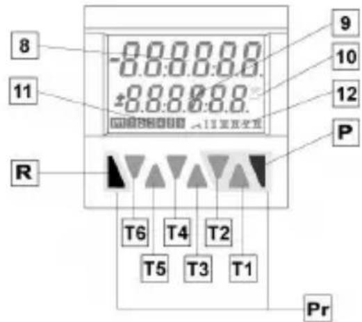
4 Display / Opera
text_image
8 11 R -0.0.0.0.0 -0.0.0.0.0 ±0.0.0.0.0 9 10 12 P T6 T4 T2 T5 T3 T1 PrT1-6 Decade key T1 ... T6
P Prog/Mode key
R Reset key
8 Current count value / main counter
9 Preset value/ Total count/ Batch counter
10 Run display for Timer
11 Shows which preset value is being displayed
12 Shows which preset output is active
Pr Keys necessary for programming the parameters (highlighted in grey)
5 Inputs
5.1 INP A, INP B
Signal inputs: function acc. to operating mode.
Max. frequency 60 kHz, can be damped in the programming menu to 30 Hz.
Pulse counter: Count inputs
Frequency meter: Frequency inputs
Timer: Start input or
S t a r t /
5.2 RESET
Dynamic reset input: resets the pulse counter or timer to zero (adding mode) or to preset value 2 (subtracting mode). The reset input can be inhibited in the programming menu.
Pulse counter: RESET input
Frequency meter: no function
T i m e r : R
5.3 G A T E
Static gate input: function depending on operating
mode. n g e l e m e n t s
Pulse counter: no counting while active
Frequency meter: no counting while active
Timer: time measurement while
a c t i v e t i m e m n o t a c
5.4 L O C K I N
Static keypad lock input for presets or programming. Lock-out level can be set in the programming menu.
5 . 5 M P I
Input. Programmable as Display Latch, Set or Teach-In input.
6 Outputs
6.1 Output
Relay with potential-free make (NO) contact or optocoupler with open emitter and collector
6.2 Output
Relay with potential-free make (NO) contact or optocoupler with open emitter and collector.
6.3 A c t i v e
An active output will be shown on the display as I or II
For safety switching the relays or optocoupler outputs can be inverted, i.e. the relay will be de-energized or the optocoupler output disabled when the presets are reached. To do this, the parameters Pr.OUT1 and Pr.OUT2 must be set to (for permanent signal) or (for timed signal).
7 Programming
7.1 Enter i
Press the Reset key and Prog/Mode key simultaneously for 3 s

text_image
Proc no PROG ΔΔΔΔΔΔ⇒ The security prompt appears in the display
Programming can be exited again using the Prog/Mode key.
Press key T2 to continue with the programming

text_image
PROG YES⇒ The security prompt appears in the display
Enter the main menu by pressing the Prog/Mode key
7.2 Choice of main menus
The menus are selected using the keys T2 (next) and T1 (back)
7.3 Enter in
The Submenu is opened with the Prog/Mode key and the first menu item is displayed.
7.4 Selecting the menu items
The Prog/Mode key is used to select a menu item within the Submenu
7.5 Setting the menu itemst s
The T2 key is used to select the individual settings for the menu items

When setting count values, each decade has a key assigned to it. Each time the key is pressed, the value increments by one
7.6 A c c e p t i
Pressing the Prog/Mode key causes the current setting to be accepted. Programming then switches to the next menu item.
7.7 Ending the programming
During programming, it is possible to exit the programming at each menu item by pressing the reset key.
Press the Reset key

⇒ The security prompt appears in the display
Pressing the Prog/Mode key acknowledges this prompt and causes the programming menu to start again from the beginning. The previously-programmed values are preserved. These can now be changed or checked again.
Pressing the decade key T2 selects the termination of the programming

⇒ The security prompt appears in the display
Pressing the Prog/Mode key acknowledges this prompt and terminates the programming; the modified settings are saved in the EEPROM.

⇒ The text SAVE is displayed for 2 s
7.8 Program
7.8.1 Default parameter

Note: Three default parameter sets have been permanently stored; these can be adapted as required. With each acknowledgment of the parameter sets, all parameters will be reset to the values listed in the table.
The dEFAuL P.USER can be freely programmed.

Menu Parameter Sets

Default setting Parameter set 1

Default setting Parameter set 2

Default setting Parameter set 3

Freely programmable User settings

Factory settings are highlighted in grey
7.8.2 Table: Parameter Sets
| P.SET 1 P.SET 2 P.SET 3 | |||
| Func C | o u | n | t |
| InP.PoL P | n | P | P |
| FiLtEr | on | oFF | oFF |
| Count | Cnt.dir | uP.dn | Quad |
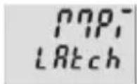
| MPi | LAtch | LAtch | Set |
| kpc.Inr | ProG | ProG | ProG |
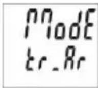
| ModE | Add | Sub | TrAiL |
| $Actor | 01.0000 | 01.0000 | 01.0000 |
| diViSo | 01.0000 | 01.0000 | 01.0000 |
| dP | 0 | 0 | 0.00 |
| SEtPt | 000000 | 000000 | 0000.00 |
| CoLor | red.Grn | red.Grn | red.Grn |
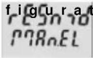
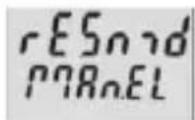
| rESmd | Man.EL | Man.EL | Man.EL |
| PrES 1 | on | on | on |
| Pr.Out 1 | |||
| t.Out 1 | 00.10 | ||
| Pr.Out 2 | |||
| t.Out 2 | 00.10 | 00.10 | |
7.8.3 Setting the Basic Function
| Funct | Basic function menu |
| Funct Count | Programming menuPulse counter (7.8.4) |
| Funct i nter | Programming menuTimer/Hour meter (7.8.6) |
| Funct tEcho | Programming menuTacho/Frequency meter (7.8.5) |
7.8.4 Pulse Counter
7.8.4.1 Mainmenu for the Signal and
C o n t r

Mainmenu for programming the signal and control inputs
Input polarity

PNP: switching to Plus for all inputs in common

NPN: switching to 0 V for all inputs in common
Filter for the signal inputs InpA and InpB

Maximum count frequency

Damped to approx. 30 Hz (for control with mechanical contacts)
Count Input mode

Count/Direction
INP A: count input
INP B: count direction input

Differential counting [A - B]
INP A: count input add INP B: count input sub
![Kübler CODIX 924 - Differential counting [A - B] - 1](/content/2026/04/616278/images/7fc8ebdb66452cd71f55ff4da1ab96da21610270c3f78729e8086440d8699efd.jpg)
Totalising [A + B]
INP A: count input add INP B: count input add
![Kübler CODIX 924 - Totalising [A + B] - 1](/content/2026/04/616278/images/a4298a69aa8b3e5b8cca46c39df5f6e5c1febafc7cd5c5506bd02b1b2a911e8c.jpg)
Quadrature input
INP A: count input 0° INP B: count input 90°

Quadrature with pulse doubling
INP A: count input 0° INP B: count input 90° Each pulse edge of INP A will be counted

Quadrature x4
INP A: count input 0° INP B: count input 90° Each pulse edge of INP A and INP B will be counted.

Ratio measurement [A / B]
Inp A: count input A Inp B: count input B
![Kübler CODIX 924 - Ratio measurement [A / B] - 1](/content/2026/04/616278/images/be7db8784cba8e2f6bf7a65a06cacf06dced668a0cb180ee47878286e093784f.jpg)
Percentage differential counting
[(A - B) / A in %] Inp A: count input A Inp B: count input B
User input

When the MPI input is activated the display is "frozen" and remains "frozen" until the MPI input is deactivated. Internally the preset counter continues counting.

When the MPI input is activated the current count value for the preset that has just been selected will be adopted as the new preset value. See also 7.9

When the MPI input is activated the preset counter will be set to the value specified in the parameter SEtPt. See also 7.10
Lock input

When the Lock input is activated the programming is inhibited.

When the Lock input is activated the setting of the preset values is inhibited.

When the Lock input is activated the setting of the preset values and the programming are both inhibited.
7.8.4.2 Mainmenu for Output operations
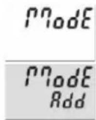
text_image
Node Node AddMainmenu for determining the operation of the outputs

Count mode ADD
Outputs active when count status ≥ preset value Reset to zero

Count mode SUBTRACT
Output 1 active when count status ≤ preset value 1 Output 2 active when count status ≤ 0 Reset to preset 2

Count mode ADDING with automatic reset
Output 1 active when count status ≥ preset value 1 Output 2 (timed signal) active when count status = preset value 2 Automatic reset to zero when count status = preset value 2 Reset to zero

Count mode SUBTRACTING with automatic reset
Output 1 active when count status < preset value 1 Output 2 (timed signal) active when count status = 0 Automatic reset to preset 2 when count status = 0 Reset to preset 2

Count mode ADDING with automatic reset and Batch counter
Output 2 (timed signal) active when main counter = preset value 2 Automatic reset to zero when main counter = preset 2 Batch counter counts the number of automatic repetitions of preset 2 Output 1 active when Batch counter > preset 1 Manual reset sets both counters to zero. Electrical reset only sets the main counter to zero.

Count mode SUBTRACTING with automatic reset and Batch counter
Output 2 (timed signal) active when main counter = zero Automatic reset to preset 2 when main counter = zero Batch counter counts the number of automatic repetitions of preset 2 Output 1 active when Batch counter ≥ preset 1 Manual reset sets main counter to preset value 2, batch counter to zero Electrical reset only sets the main counter to preset value 2

Count mode ADDING with automatic reset and Total counter
Output 2 (timed signal) active when main counter = preset value 2 Automatic reset to zero when main counter = preset value 2 Total counter counts all the count pulses from the main counter Output 1 active when total counter > preset value 1 Manual Reset sets both counters to zero Electrical reset only sets the main counter to zero

Count mode SUBTRACTING with automatic reset and Total counter
Output 2 (timed signal) active when main counter = zero Automatic reset to preset value 2 when main counter = zero Total counter counts (sub from preset value 1) all count pulses from main counter Output 1 active when Total counter ≤ zero Manual reset sets both counters to the preset values Electrical reset sets only main counter to preset value 2

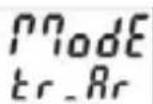
Tracking Preset mode
When preset 2 is changed then preset 1 automatically tracks it. Reset to zero Preset 1 relative to preset 2 (see also section 17. Output operations)
Tracking Preset mode with automatic reset
When preset 2 is changed then preset 1 automatically tracks it. Reset to zero. Automatic reset to zero when main counter = preset value 2. Preset 1 relative to Preset 2 (see also section 17. Output operations)
7.8.4.3 Main menu for con
i Manual reset (with red key) and electrical reset (reset input)

Mainmenu for matching the input pulses and display

text_image
rESn no rES rESn EL rESNo reset possible (red key and reset input inhibited)
Multiplication factor

Multiplication factor can be programmed from 00.0001 to 99.9999.

Only electrical reset possible (reset input)
The setting 00.0000 will not be accepted
Division factor
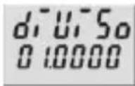
Division factor can be programmed from 01.0000 to 99.9999. The setting <01.0000 will not be accepted
7.8.4.5 Preset 1
See below 7.8.6.5
7.8.4.6 Preset 2
See below 7.8.6.8
Decimal point setting

Decimal point (only optical function)
0 no decimal place
0.0 1 d e c i 0.00 2 d e c i m a l p l
0.00 0 3 decimal places
0 . 0 0 0 0 0 0 . 0 0 0 0 0 5
7.8.5 Tacho/Frequency meter
7.8.5.1 Mainmenu for the Signal and Control inputs
a c e s I n P u t Mainmenu for programming the signal and control inputs 4 d e c i m a l p l a c e
Set value

Set value can be programmed from -999999 to 999999
A previously programmed decimal point will be displayed
Input polarity
text_image
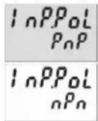
InPPoL PnP InPPoL nPnPNP: switching to Plus for all inputs in common
NPN: switching to 0 V for all inputs in common
Display colour (for device 6.92x.x1x3.xx0)

Display colour
upper line red
lower line red
Filter for the signal inputs Inp A and Inp B

maximum count frequency

Display colour
upper line red
lower line green

damped to approx. 30 Hz (for control with mechanical contacts)
7.8.4.4 Mainmenu for reset mode

Setting the reset mode
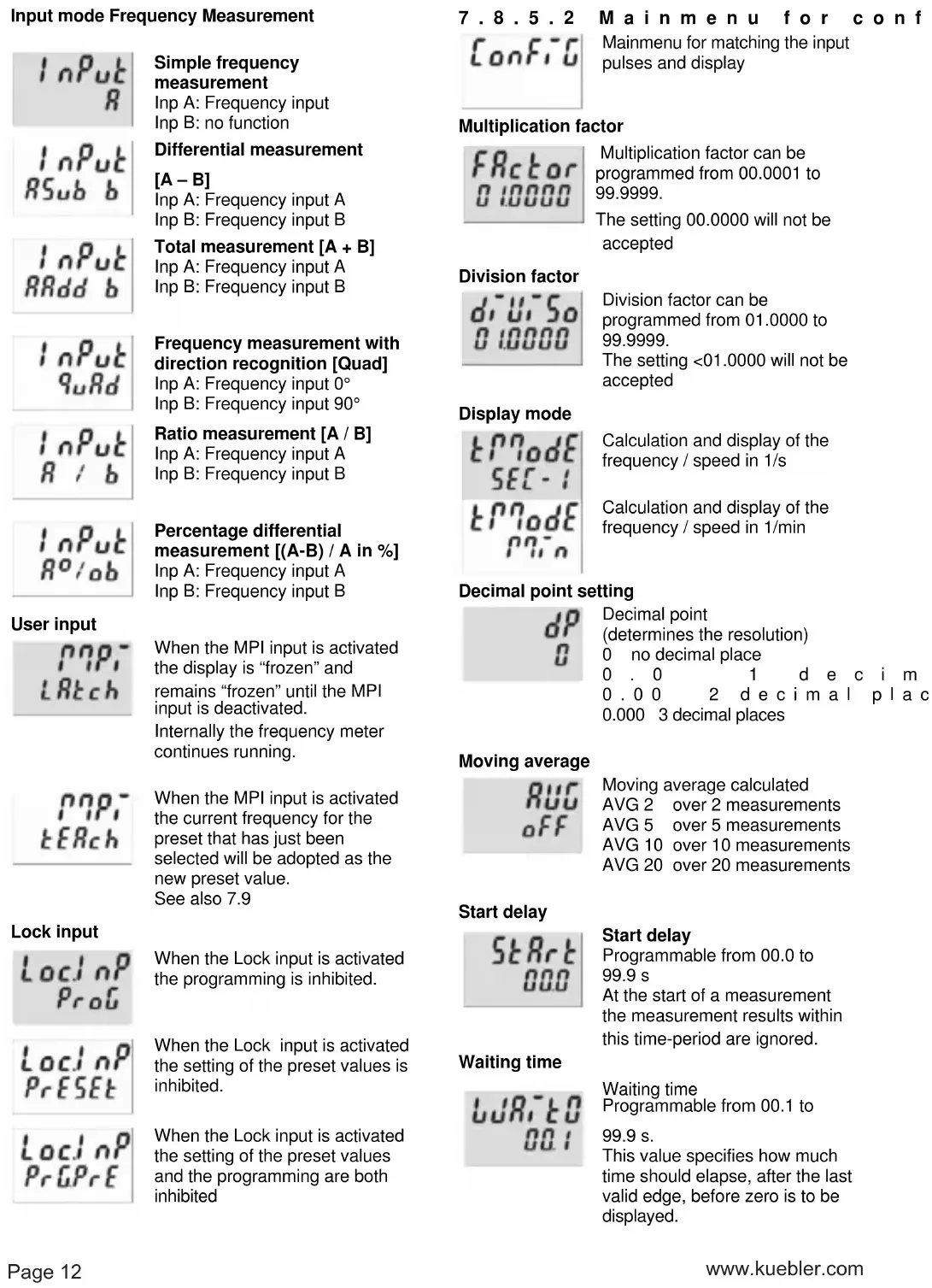
Input mode Frequency Measurement

Simple frequency measurement
Inp A: Frequency input
Inp B: no function

Differential measurement
[A-B]
Inp A: Frequency input A
Inp B: Frequency input B

Total measurement [A + B]
Inp A: Frequency input A
Inp B: Frequency input B
![Kübler CODIX 924 - Total measurement [A + B] - 1](/content/2026/04/616278/images/f0fdea1f98143a1555c4df33efd1a96ba10767fbb8ba98e515b9a376452e4998.jpg)
Frequency measurement with direction recognition [Quad]
Inp A: Frequency input 0°
Inp B: Frequency input 90°
![Kübler CODIX 924 - Frequency measurement with direction recognition [Quad] - 1](/content/2026/04/616278/images/33ce8cfa6df51f473dabebcdcb9fb9b7648259685b2063e629c700b393d3279b.jpg)
Ratio measurement [A / B]
Inp A: Frequency input A
Inp B: Frequency input B
![Kübler CODIX 924 - Ratio measurement [A / B] - 1](/content/2026/04/616278/images/2347f1186912dddd7e6dbb2a7fc2a6decb2b1585ade5b7e1bdbbe0315b80c8b4.jpg)
Percentage differential measurement [(A-B) / A in %]
Inp A: Frequency input A
Inp B: Frequency input B
User input

When the MPI input is activated the display is "frozen" and remains "frozen" until the MPI input is deactivated.
Internally the frequency meter continues running.

When the MPI input is activated the current frequency for the preset that has just been selected will be adopted as the new preset value.
See also 7.9
Lock input

When the Lock input is activated the programming is inhibited.

When the Lock input is activated the setting of the preset values is inhibited.

When the Lock input is activated the setting of the preset values and the programming are both inhibited
7.8.5.2
Main menu for conf

Mainmenu for matching the input pulses and display
Multiplication factor

Multiplication factor can be programmed from 00.0001 to 99.9999.
The setting 00.0000 will not be accepted
Division factor
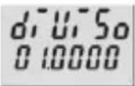
Division factor can be programmed from 01.0000 to 99.9999.
The setting <01.0000 will not be accepted
Display mode
Calculation and display of the frequency / speed in 1/s

Calculation and display of the frequency / speed in 1/min
Decimal point setting

Decimal point (determines the resolution) 0 no decimal place
0.0 1 d e c i m 0.00 2 d e c i m a l p l a c 0.000 3 decimal places
Moving average

Moving average calculated
AVG 2 over 2 measurements
AVG 5 over 5 measurements
AVG 10 over 10 measurements
AVG 20 over 20 measurements
Start delay

Start delay
Programmable from 00.0 to 99.9 s
At the start of a measurement the measurement results within this time-period are ignored.
Waiting time

Waiting time
Programmable from 00.1 to 99.9 s.
This value specifies how much time should elapse, after the last valid edge, before zero is to be displayed.
Display colour (for device 6.92x.x1x3.xx0)

Display colour
Upper line red
Lower line red

Display colour
Upper line red
Lower line green
7.8.5.3 Preset 1
See below 7.8.6.5
7.8.5.4 Preset 2
See below 7.8.6.6
7.8.6 Timer
7.8.6.1 Mainmenu for the Signal and
C o n t r

Mainmenu for programming the signal and control inputs
Input polarity

PNP: switching to Plus for all inputs in common

nPn: switching to 0 V for all inputs in common
Filter for the signal inputs Inp A and Inp B

for electronic control of the signal inputs

for mechanical control of the signal inputs(for control with mechanical contacts)
Input mode Time measurement

Start: Edge to Inp A
Stop: Edge to Inp B

Start: 1. Edge to Inp B
Stop: 2. Edge to Inp B

Timing can only be controlled via the Gate input
Inp A and Inp B: no function

The timer is reset by means of a RESET (to zero when adding, to preset 2 when subtracting) and then starts timing again.
Timing is stopped with adding operations when preset 2 is reached.
Timing is stopped with subtracting operations when zero is reached.
A RESET during the timing process also causes this to stop.
Inp A and Inp B: no function.
o l i n p
Gate control for Timing

Timing takes place when the Gate input is not active.

Timing takes place when the Gate input is active
User input
When the MPI input is activated the display is "frozen" and remains "frozen" until the MPI input is deactivated.
Internally the preset timer continues counting.

When the MPI input is activated the current count value for the preset that has just been selected will be adopted as the new preset value.
See also 7.9

When the MPI input is activated the preset timer will be set to the value specified in the parameter SEtPt. See also 7.10
Lock input

When the Lock input is activated the programming is inhibited.

When the Lock input is activated the setting of the preset values is inhibited.

When the Lock input is activated the setting of the preset values and the programming are both inhibited.
7.8.6.2 Mainmenu for the output operations

Mainmenu for determining the operation of the outputs

Count mode ADD
Outputs active when count status
preset value Reset to zero

Count mode SUBTRACT
Output 1 active when count status ≤ preset value 1 Output 2 active when count status ≤ 0 Reset to preset 2

Count mode ADDING with automatic reset
Output 1 active when count status > preset value 1 Output 2 (timed signal) active when count status = preset value 2 Automatic reset to zero when count status = preset value 2 Reset to zero

Count mode SUBTRACTING with automatic reset
Output 1 active when count status ≤ preset value 1 Output 2 (timed signal) active when count status = 0 Automatic reset to preset 2 when count status = 0 Reset to preset 2

Count mode ADDING with automatic reset and Batch counter
Output 2 (timed output) active when main counter = preset value 2 Automatic reset to zero when
main counter = preset value 2 Batch counter counts the number of automatic repetitions of preset 2 Output 1 active when batch counter > preset 1 manual reset sets both counters to zero electrical reset sets only main counter to zero

Count mode SUBTRACTING with automatic reset and Batch counter
Output 2 (timed signal) active when main counter = zero Automatic reset to preset 2 when main counter = zero Batch counter counts the number of automatic repetitions of preset 2 Output 1 active bei Batchzähler > Preset 1
Manual reset sets main counters to preset value 2 and batch counter to zero Electronic reset only sets the main counter to preset value 2

Count mode ADDING with automatic reset and Total counter
Output 2 (timed signal) active when main counter = preset value 2 Automatic reset to zero when main counter = preset value 2 Total counter counts all the count pulses from the main counter Output 1 active when total counter > preset value 1 Manual Reset sets both counters to zero Electronic reset only sets the main counter to zero

Count mode SUBTRACTING with automatic reset and Total counter
Output 2 (timed signal) active when main counter = zero Automatic reset to preset value 2 when main counter = zero Total counter counts (sub from preset value 1) all count pulses from main counter Output 1 active when Total counter < zero Manual reset sets both counters to the preset values Electronic reset sets only main counter to preset value 2
Tracking preset mode

When preset 2 is changed then preset 1 automatically tracks it. Reset to zero
Preset 1 relative to preset 2 (see also section 17. Output operations)
Tracking Preset mode with automatic reset
When preset 2 is changed then preset 1 automatically tracks it. Reset to zero.
Automatic reset to zero when main counter = preset value 2. Preset 1 relative to Preset 2 (see also section 17. Output operations)
7.8.6.3 Mainmenu for configuration

Mainmenu for matching the time ranges and display
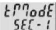
Unit of time
Unit of time: seconds Decimal point setting determines the resolution

Unit of time: minutes Decimal point setting determines the resolution

Unit of time: hours Decimal point setting determines the resolution

Unit of time: Hrs. Min. Sec.

Decimal point setting (Resolution)

Decimal place (determines the resolution) 0 no decimal place
0.0 1 d e c i m a l p l 0.00 2 d e c i m a l p l a c e s 0.000 3 decimal places
Set value

Set value can be programmed from 000000 to 999999 A previously programmed decimal point will be displayed
Display colour (for 6.92x.x1x3.xx0]
![Kübler CODIX 924 - Display colour (for 6.92x.x1x3.xx0] - 1](/content/2026/04/616278/images/1141629314d7ba15620adcb49db52d49c1daad5ebba743f69be9b215b5d85f3e.jpg)
Display colour upper line red lower line red
![Kübler CODIX 924 - Display colour (for 6.92x.x1x3.xx0] - 2](/content/2026/04/616278/images/7ec4f95310080f96cfa6d26a7c2d6b06e2ea72de15f81771438190db7bb16860.jpg)
Display colour upper line red lower line green
7.8.6.4 Mainmenu for reset mode

Setting the reset mode
Manual reset (with red key) and electrical reset (reset input)

No reset possible (red key and reset input inhibited)

Only electrical reset possible (reset input)

Only manual reset possible (red key)
7.8.6.5 Mainmenu for Preset 1

Mainmenu for turning preset 1 ON/OFF

Preset 1 ON

Preset 1 OFF and no function

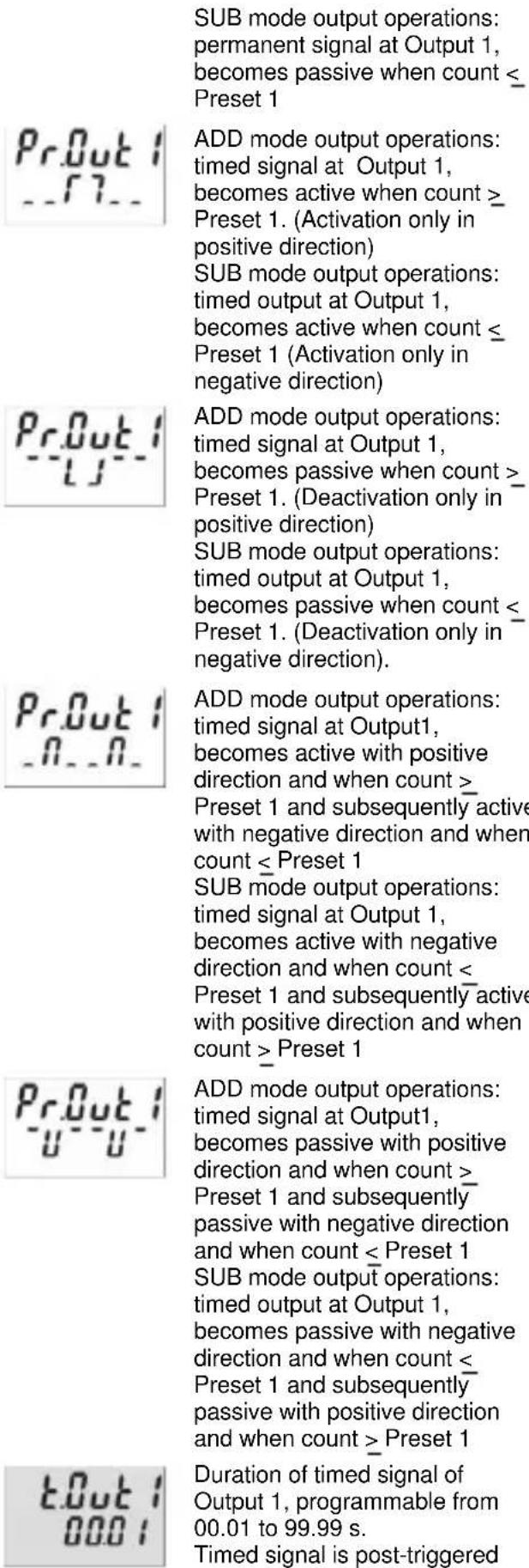
ADD mode output operations: permanent signal at Output 1, becomes active when count > Preset 1

SUB mode output operations: permanent signal at Output 1, becomes active when count < Preset 1
ADD mode output operations: permanent signal at Output 1, becomes passive when count > Preset 1
text_image
SUB mode output operations: permanent signal at Output 1, becomes passive when count ≤ Preset 1 Pr.Out 1 __7__ ADD mode output operations: timed signal at Output 1, becomes active when count ≥ Preset 1. (Activation only in positive direction) SUB mode output operations: timed output at Output 1, becomes active when count ≤ Preset 1 (Activation only in negative direction) Pr.Out 1 __5__ ADD mode output operations: timed signal at Output 1, becomes passive when count >_ Preset 1. (Deactivation only in positive direction) SUB mode output operations: timed output at Output 1, becomes passive when count ≤_ Preset 1. (Deactivation only in negative direction). Pr.Out 1 __0__. ADD mode output operations: timed signal at Output1, becomes active with positive direction and when count >_ Preset 1 and subsequently active with negative direction and when count ≤ Preset 1 SUB mode output operations: timed signal at Output 1, becomes active with negative direction and when count <_ Preset 1 and subsequently active with positive direction and when count > Preset 1 Pr.Out 1 __u__- ADD mode output operations: timed signal at Output1, becomes passive with positive direction and when count >_ Preset 1 and subsequently passive with negative direction and when count ≤ Preset 1 SUB mode output operations: timed output at Output 1, becomes passive with negative direction and when count ≤ Preset 1 and subsequently passive with positive direction and when count > Preset 1 t.Out 1 000: Duration of timed signal of Output 1, programmable from 00.01 to 99.99 s. Timed signal is post-triggered7.8.6.6 Mainmenu for Preset 2
text_image
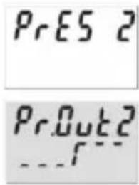
PrES 2 PrOut2Mainmenu for Preset 2

ADD mode output operations: permanent signal at Output 2, becomes active when count > Preset 2
SUB mode output operations: permanent signal at Output 2, becomes active when count < zero
ADD mode output operations: permanent signal at Output 2, becomes passive when count > Preset 2
SUB mode output operations: permanent signal at Output 2, becomes passive when count < zero

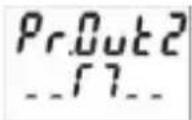
ADD mode output operations: timed signal at Output 2, becomes active when count > Preset 2 (Activation only in positive direction). SUB mode output operations: permanent signal at Output 2, becomes active when count < zero (Activation only in negative direction)

ADD mode output operations: timed signal at Output 2, becomes passive when count > Preset 2 (Deactivation only in positive direction)
SUB mode output operations: permanent signal at Output 2, becomes passive when count < zero (Deactivation only in negative direction).

ADD mode output operations:
timed signal at Output 2,
becomes active with positive
direction and when count > Preset 2 and subsequently with
negative direction and when
count < Preset 2
SUB mode output operations:
timed signal at Output 2,
becomes active with negative
direction and when count < zero
and subsequently with positive
direction and when count > zero

Preset 2 and subsequently with negative direction and when count < Preset 2
SUB mode output operations: timed signal at Output 2, becomes passive with negative direction and when count < zero and subsequently with positive direction and when count > zero
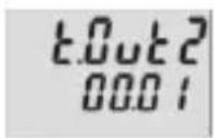
Duration of timed signal of Output 1, programmable from 00.01 to 99.99 s.
Timed output is post-triggered.
Active:
Relay or optocoupler are activated when the preset value is reached.
Passive:
Relay becomes de-energized or the optocoupler disabled when the preset value is reached.
7.9 Setting the presets
7.9.1 Setting via Decade Keys
In programming mode Preset 2 will always be displayed in the lower line. This is except for the output operations AddBat, SubBat, AddTot and SubTot.
Press the Prog/Mode key until the preset to be changed is displayed - PR1 or PR2
Press any decade key
→ Display switches to the editor mode
Set the desired preset value using the decade keys
Press the Prog/Mode key to confirm the value and save it
→ Display switches to the editor mode of the next preset PR2 or PR1
Approx. 3 s after the last press of the decade keys or by pressing the Reset key the new preset value will be accepted and the counter will switch back to operating mode.
7.9.2 Setting with Teach-In Function

Program the MPI input to tEAch
In programming mode, select the preset to be changed using the Prog/Mode key
Briefly activate the MPI (NPN or PNP input logic)
⇒ The current count value will be adopted as the new preset value

The preset value can subsequently be further modified via the decade keypad.
7.9.3 Setting the tracking presets (trail)
If a tracking preset has been programmed, the value for Preset 2 can be set either via the decade keypad or via the Teach-IN function.
However the value for Preset 1 must be entered via the decade keypad. In this instance, it is not possible to use the Teach-In function.
7.10 Set Function
Both the pulse counter and the timer can be set to a default value by means of the Set function.

Programme the MPI input to SEt

Set menu item SEtPt to the desired value
Briefly activate the MPI (NPN or PNP input logic)
⇒ For add. output operations the pulse counter or timer will be set to the SEtPt default value
⇒ For sub. output operations the pulse counter or timer will be set to the amount of the value of Preset 2 and the value of SEtPt.
8 Error message
Err 1 Set value is outside the permitted range
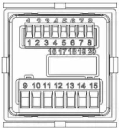
9 Connections
text_image
1 2 3 4 5 6 7 8 10 17 18 19 30 9 10 11 12 13 14 159.1 Signal and Control Inputs
| N° | D e | s i |
| 1 | AC: 24 VDC/80 mADC: UB connected through | Sensor supply voltage |
| 2 | GND (0 VDC) Common connection | Signal and Control inputs |
| 3 | INP A Signal input A | |
| 4 | INP B Signal input B | |
| 5 | R E S E T | R e s e t i n |
| 6 | L O C K K | e y p a d l o |
| 7 | G A T E G | a t e i n p u |
| 8 | M P I U s e | r i n p u t |
9.2 Supply
9.2.1 Version with relay
| N° | Designation | Function |
| 9 | Relay contact C.1 | Output 1 |
| 10 | Relay contact N.O.1 | |
| 11 | Relay contact C.2 | Output 2 |
| 12 | Relay contact N.O.2 | |
| 13 | Relay contact N.C.2 | |
| 14 | AC: 100 ... 240 VAC ± 10% N~AC: 24 VAC N~DC: 10..30 VDC | Supply voltage |
| 15 | AC: 100 ... 240 VAC ± 10% L~AC: 24 VAC L~DC: GND (0 VDC) | Supply voltage |
9.2.2 Version with Optoc
| N° | Designation | Function |
| 9 | C o l l e c t o r 1 | Output 1 |
| 10 | Emitter | |
| 11 | Emitter 2 | Output 2 |
| 12 | Not connected | |
| 13 | Collector 2 | |
| 14 | AC: 100 ... 240 VAC ± 10% N~DC: 10..30 VDC | Supply voltage |
| 15 | AC: 100 ... 240 VAC ± 10% L~DC: GND (0 VDC) | Supply voltage |
10 Technical Data
| g 10.1 General Data | ||
| h a t i | ||
| Display | LCD positive or negative, backlit2 x 6-digit | |
| Digit height | upper line lower line special characters | 9 mm7 mm2 mm |
| Overload/Underload | Blinking, 1 sCounter loses up to 1 decade no pulses | |
| Data retention | >10 years, EEPROM | |
| Operation | 8 keys | |
| u t k | ||
10.2 Pulse counter
Count frequency max. 55 kHz (see section 13. frequencies typ.)
Response time of the outputs:
| Relays | o | l | t | a | g | e | a | n |
| Add/Sub/Trail | < 13 ms | |||||||
| s | With automatic repeat | < 13 ms | ||||||
| A/B ; (A-B)/A | < 34 ms | |||||||
| Optocouplers | ||||||||
| Add/Sub/Trail | < 1 ms | |||||||
| With automatic repeat | < 1 ms | |||||||
| A/B ; (A-B)/A | < 23 ms | |||||||
10.3 Tacho/Frequency meter
| Frequency range | 0,01 Hz to 65 kHz (see section 13. frequencies typ.) In case of frequencies <10 Hz, the waiting time must be increased accordingly to obtain the display of a value. |
| Measuring principle | ≤76.3 Hz Time interval (period measurement) >76.3 Hz Gate time Gate time approx.13.1 ms |
| Measuring error | <0.1% per channel |
Response time of the outputs:
1-channel operation < 100 ms @ 40 kHz < 350 ms @ 65 kHz
2-channel operation < 150 ms @ 40 kHz < 600 ms @ 65 kHz
10.4 Timer
Seconds 0.001 s ... 999 999 s
Minutes 0.001 min ... 999 999 min
Hours 0.001 h .. 999 999 h
h . m i n . s 0 0 h 9 9 h .
Min. time measurable 500μs
Measuring error < 50 ppm
Response time of the outputs:
R e l a y s < 1 3
Optocoupler < 1 ms
10.5 Signal and Control inputs
SELV circuits, reinforced / double insulation
Polarity: programmable NPN/PNP for all inputs in common
Input resistance 5 kΩ
Pulse shape any
Switching level with AC supply:
HTL level Low: 0 ... 4 VDC
High: 12 ... 30 VDC
4-30 V level Low: 0 ... 2VDC
High: 3,5 ... 30 VDC
Switching level with DC supply:
HTL level Low: 0 ... 0,2 x UB
High: 0,6 x UB ... 30 VDC
4-30 V level Low: 0 ... 2 VDC
High: 3,5 ... 30 VDC
Minimum pulse length of the Reset input: 1 ms
Minimum pulse length of the Control inputs:10 ms
10.6 Outputs
Output 1
Relay with make contact
Prescribed fuse: 3A
programmable as NC or NO
Switching voltage max. 250 VAC/110 VDC
Switching current max. 3 A AC/ V DC
mi n . 3 0
Switching capacity max. 750 VA / 90 W

The maximum values shall in no case be exceeded!
Mechanical service life (switching cycles) 2x10 7
N° of switching cycles at 3 A/250 V AC 1x10 5
N° of switching cycles at 3 A/ 30 V DC 1x10 5
or NPN optocoupler
Switching capacity 30 VDC/10 mA
U_CESAT for IC = 10 mA: max. 2.0 V
U_CESAT for IC = 5 mA: max. 0.4 V
Output 2
Relay with changeover contact
Prescribed fuse: 3A
Switching voltage max. 250 VAC/150 VDC
Switching current max. 3 A AC/ A DC
mi n . 3 0
Switching capacity max. 750 VA/90 W

The maximum values shall in no case be exceeded!
0 min. 01s...
5Mechanical service life (switching cycles) 20x10 ^6 s
N° of switching cycles at 3 A/250 V AC 5x10 ^4
N° of switching cycles at 3 A/ 30 V DC 5x10 4
mor N\$PN optocoupler
Switching capacity 30 V DC/10 mA
U_CESAT for IC = 10 mA: max. 2.0 V
U_CESAT for IC = 5 mA: max. 0.4 V
1 0 . 7 S u p p l y v o l
AC supply: 100 ... 240 V AC / max. 9.5 VA
50/ 60 Hz, Tolerance ± 10%
ext. fuse protection: T 0.1 A
24 VAC +/- 10% / max. 6 VA
50 / 60 Hz
ext. fuse protection: T 0,315 A
DC supply: 10 ... 30 V DC/ max. 5 W
re ve r s e
SELV, CLASS II (Limited
Power Source)
ext. fuse protection T 0.2 A
10.8 Sensor su
(Voltage output for external sensors)
SELV circuits, reinforced / double insulation
for AC supply: 24 V DC ±15%, 80 mA
for DC supply: max. 80 mA, external voltage
supply is connected through
10.9 Climatic C
Operating temperature: -20°C .. +65°C
Storage temperature: -25°C .. +75°C
Relative humidity: RH. 93% at +40°C,
A l t i t u d e : n o n -c o t o 2 0
10.10 EMC
Noise immunity: EN 61000-6-2
with shielded signal and
control cables
Noise emission: EN 55011 Class B
10.11 Device safety
Design to: EN 61010 Part 1
Protection Class: Protection Class 2 (front side)

Only the front side is classified as accessible for the operator.
Application area: Pollution level 2
o v e r
Insulation: Front: double insulation,
Rear side: basic insulation,
Signal inputs and und sensor power supply: SELV
10.12 Mechanical Data
H o u s i n g :
P a n e l -
to DIN 43 700, RAL 7021
Dimensions: 48 x 48 x 91 mm
Panel cut-out: 45 ^+0,6 x 45 ^+0,6 mm
Installation depth: ca. 107 mm incl. terminals
Weight: ca. 125 g
Protection: IP65 (front, device only)
Housing material: Polycarbonate UL94 V-2
Vibration resistance: 10 - 55 Hz / 1 mm / XYZ
(EN 60068-2-6): 30 min in each direction
Shock resistance:
EN 60068-2-27 100G / 2 ms / XYZ
3 times in each direction
EN 60068-2-29 10G / 6 ms / XYZ
2000 times in each direction
10.13 Connections
Supply voltage and outputs:
Plug-in screw terminal, 7-pin, RM5.08
Core cross section, max. 2.5 mm ^4
Signal and control inputs:
Plug-in screw terminal, 8-pin, RM 3.81
Core cross-section, max. 1.5 mm ^4
11 Scope of Delivery
Delivery includes:
Preset counter
Mounting clip
Instruction manual
12 Ordering codes
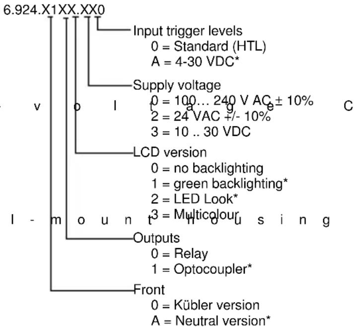
flowchart
graph TD
    A["6.924.X1XX.XX0"] --> B["Input trigger levels"]
    B --> C["0 = Standard (HTL)"]
    B --> D["A = 4-30 VDC*"]
    A --> E["Supply voltage"]
    E --> F["0 = 100...240 V AC ± 10%"]
    E --> G["2 = 24 VAC +/- 10%"]
    E --> H["3 = 10..30 VDC"]
    A --> I["LCD version"]
    I --> J["0 = no backlighting"]
    I --> K["1 = green backlighting*"]
    I --> L["2 = LED Look*"]
    I --> M["3 = Multicolour"]
    A --> N["Outputs"]
    N --> O["0 = Relay"]
    N --> P["1 = Optocoupler*"]
    A --> Q["Front"]
    Q --> R["0 = Kübler version"]
    Q --> S["A = Neutral version*"]
* 24 VAC power supply on request
13 Frequencies (typical)
13.1 Pulse counter
HTL level
| AC supply | typ. Low | 2,5 V | |||
| t | y | p | . | ||
| DC supply 12V | typ. Low | 2 V | |||
| t | y | p | . | ||
| DC supply 24V | typ. Low | 2,5 V | |||
| t | y | p | . | ||
| Add Sub Trail | AddAr SubAr AddBat SubBat TrailAr | AddTot SubTot | |
| Cnt.Dir | 55 kHz | 2,8 kHz | 2,7 kHz |
| Up.Dn Up.Up | 29 kHz | 2,8 kHz | 2,7 kHz |
| Quad Quad 2 | 28 kHz | 1,4 kHz | 1,3 kHz |
| Quad 4 | 18 kHz | 1,2 kHz | 0,9 kHz |
| A/B (A-B)/A | 29 kHz | ||
4-30 V level
typ. Low 1,0 V
typ. High 4,0 V
| Add Sub Trail | AddAr SubAr AddBat SubBat TrailAr | AddTot SubTot | |
| Cnt.Dir | 9 kHz 2,7 | kHz 2,4 kHz | |
| Up.Dn Up.Up | 9 kHz 2,7 | kHz 2,4 kHz | |
| Quad Quad 2 | 9 kHz 1,2 | kHz 1,2 kHz | |
| Quad 4 | 9 kHz 1,2 | kHz 0,9 kHz | |
| A/B (A-B)/A | 9 kHz | ||
1 3 . 2 Frequency meter
HTL level
AC supply typ. Low 2,5 V
| t | y | p | . | ||
| DC supply 12V | typ. Low | 2 V | |||
| t | y | p | . | ||
| DC supply 24V | typ. Low | 2,5 V | |||
| t | y | p | . |
| H | i | g | h | 2 | 2 |
| H | i | g | h | 1 | 0 |
| H | i | g | h | 2 | 2 |
4-30 V level
| H | T | |
| A | 65 kHz | 9 kHz |
| A - BA + BA / B(A-B)/A | 65 kHz | 9 kHz |
| Quad | 30 kHz | 9 kHz |
| L | o | w | 1 | , | 0 | ||
| H | i | g | h | 4 | , | 0 | |
| L | 5 |
NOTE: Switching levels of the input
Switching levels with AC supply:
HTL level Low: 0 .. 4 VDC
High: 12 .. 30 VDC
4-30 V level Low: 0 .. 2VDC
High: 3,5 .. 30 VDC
Switching levels with DC supply:
HTL level Low: 0 .. 0,2 x UB
High: 0,6 x UB .. 30 VDC
4-30 V level Low: 0 .. 2 VDC
High: 3,5 .. 30 VDC
14 Input modes: Pulse counting
| Function DiagramNote: No counting when GATE input is activeP = Preset | PNP: Count on rising edgeNPN: Count on falling edge | ||
| C n | 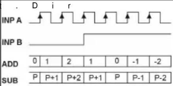 | np A: Count inputnp B: Count directionAdd: Display 0 --> PresetSub: Display Preset -> 0 | |
| U p | 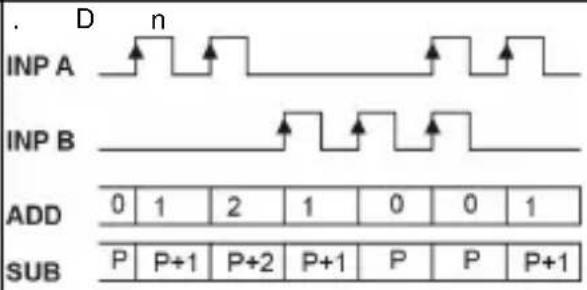 | np A: Count input addnp B: Count input subAdd: Display 0 --> PresetSub: Display Preset -> 0 | |
| U p | 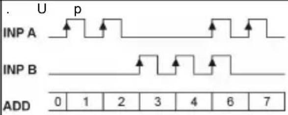 | np A: Count input 1 addnp B: Count input 2 addAdd: Display 0 --> Preset | |
| Q u | 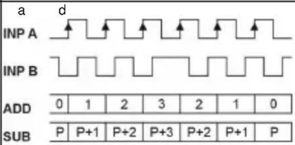 | A 90° Bnp A: Count inputCount on one edgenp B: Reverse directionAdd: Display 0 --> PresetSub: Display Preset -> 0 | |
| Quad 2 | 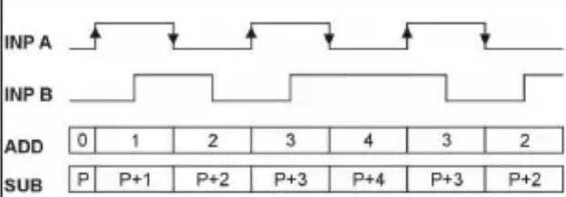 | A 90° Bnp A: Count inputCount on rising and on falling edgesnp B: Reverse directionAdd: Display 0 --> PresetSub: Display Preset -> 0 | |
| Function DiagramNote: No counting when GATE input is active | PNP: Count on rising edgeNPN: Count on falling edge | |
| Quad 4 | 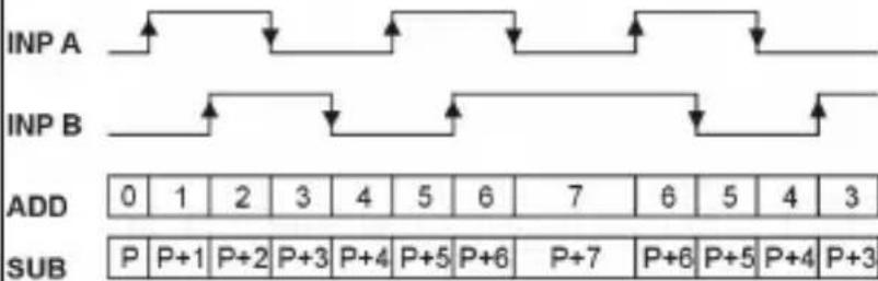 | A 90° BInp A: Count inputCount on rising and on falling edgesInp B: Count inputCount on rising and on falling edges,Reverse directionAdd: Display 0 --> PresetSub: Display Preset -> 0 |
| A / B | INPACounts A0111234INPBCounts B0123344Display010.50.330.660.751 | Inp A: Count input 1Inp B: Count input 2Formula:A / B |
| ( A - | B) / AINPACounts A0111234INPBCounts B0123344Display0%0%-100%-200%-50%-33%0% | Inp A: Count input 1Inp B: Count input 2Formula:(A-B)/A x100 |
15 Input modes: Timing
| Function Diagram PNP: Count on rising edge | NPN: Count on falling edge | ||||||||
| In A | INP A | 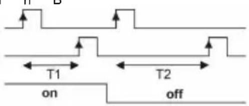 | Inp A: StartInp B: StopAdd: Display 0 --> PresetSub: Display Preset -> 0 | ||||||
| INP B | |||||||||
| GATE | |||||||||
| ADD | |||||||||
| SUB | |||||||||
| In B | INP B | 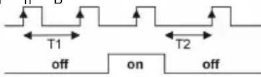 | Inp A: no functionInp B: Start/StopAdd: Display 0 --> PresetSub: Display Preset -> 0 | ||||||
| GATE | |||||||||
| ADD | |||||||||
| SUB | |||||||||
| F r R | GATE | 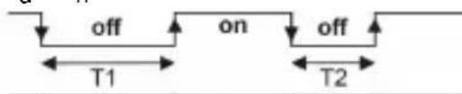 | Inp A: no functionInp B: no functionControl of the timing only via the GATE inputAdd: Display 0 --> PresetSub: Display Preset -> 0 | ||||||
| ADD | |||||||||
| SUB | |||||||||
| Auto | GATE | 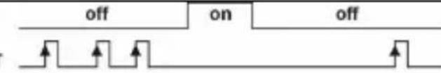 | Inp A: no functionInp B: no functionControl of the timing via RESET (manual or electrical)Add: Display 0 --> PresetSub: Display Preset -> 0 | ||||||
| RESET | |||||||||
| PRESE | 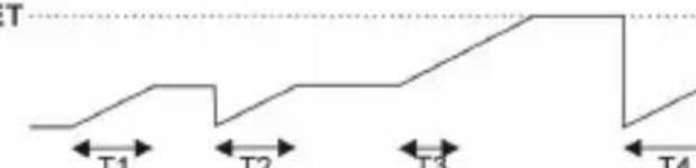 | ||||||||
| ADD | |||||||||
| SUB | 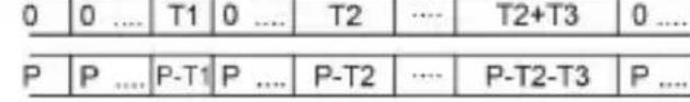 | ||||||||
16 Input modes: Frequency meter
| Function Diagram PNP: Count on rising edge | NPN: Count on falling edge | |
| A | 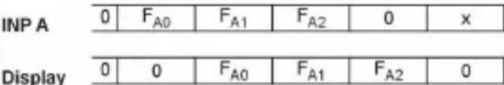 | Inp A: Frequency inputInp B: no function |
| A s | u b B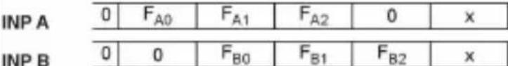  | Inp A: Frequency input 1Inp B: Frequency input 2Formula:A - B |
| A a | d d B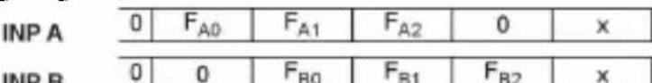  | Inp A: Frequency input 1Inp B: Frequency input 2Formula:A + B |
| Q u | a d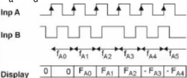 | A 90° BInp A: Frequency input 1Inp B: Reverse direction |
| A / B | 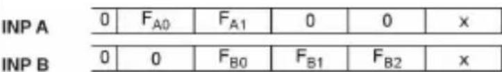  | Inp A: Frequency input 1Inp B: Frequency input 2Formula:A / B |
| ( A - | B ) / A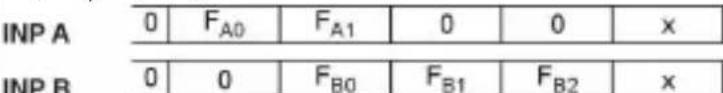  | Inp A: Frequency input 1Inp B: Frequency input 2Formula:(A-B)/A x100 |
17 Output operations
| M o | d e | D i a g r a m | M | o d e | D i a g r a m |
 |  | ||||
| A d | d | 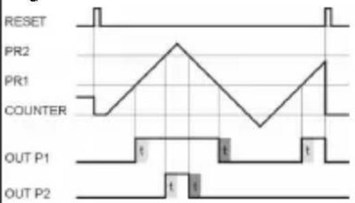 | S u | b | 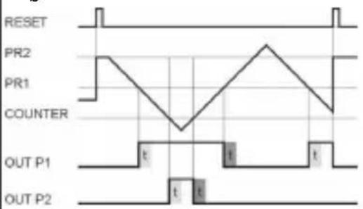 |
| A d d | A r | 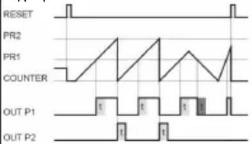 | S u b | A r | 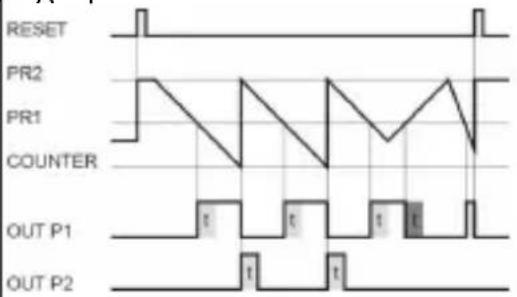 |
| A d d | B at | 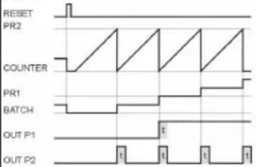 | S u b | B at | 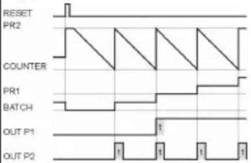 |
| A d d | T o t | 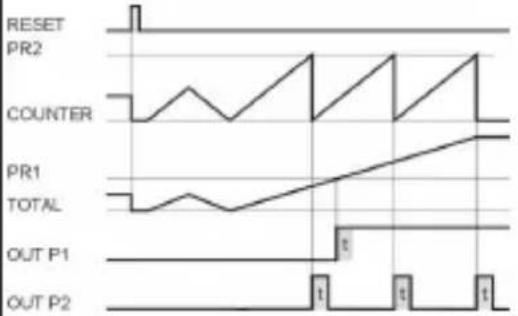 | S u b | T o t | 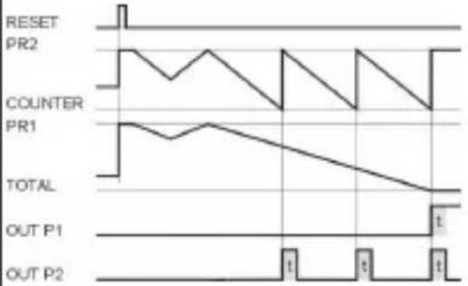 |
| M o | d e | D i a g r a m |
| T r | a i l | |
| RESET | ||
| PR1 | ||
| PR2 | ||
| PR1 | ||
| COUNTER | 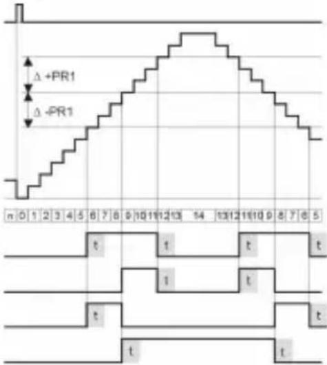 | |
| OUT P1Δ +/-PR1 | ||
| OUT P1Δ +PR1 | ||
| OUT P1Δ -PR1 | ||
| OUT P2 | ||
| T r a | i l A r | |
| RESET | ||
| PR1 | ||
| PR2 | ||
| PR1 | ||
| COUNTER | 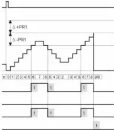 | |
| OUT P1Δ +/-PR1 | ||
| OUT P1Δ +PR1 | ||
| OUT P1Δ -PR1 | ||
| OUT P2 | ||
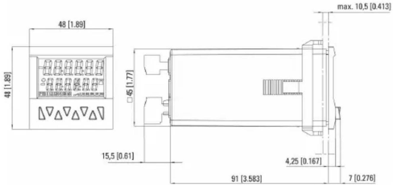
18 Dimensional Drawings
Dimensions in mm [inch]
text_image
48 [1.89] 48 [1.89] 45 [1.77] 15,5 [0.61] max. 10,5 [0.413] 4,25 [0.167] 91 [3.583] 7 [0.276]Panel cut-out
text_image
45⁺⁰°⁰ [1.772⁺⁰°²⁴] 45⁺⁰°⁵ [1.772⁺⁰°²⁴]CODIX 924

text_image
Kubler 123458 123456Kübler
Add, Sub, AddAr, SubAr, AddBat, SubBat, AddTot, SubTot, Trail, TrailAr
text_image
Funcct Funcct CountAdd; Sub; Trail < 13 ms
SELV, CLASS II (Limited
Power Source)
| H | T | |
| A | 65 kHz 9 kHz | |
| A - BA + BA / B(A-B)/A | 65 kHz 9 kHz | |
| Quad | 30 kHz 9 kHz |
| B | a | s | 1 | , | 0 | ||
| H | a | u | t | 4 | , | 0 | |
| L | 5 |
text_image
45+0.6 [1.772+0.024] 45+0.6 [1.772+0.024]CODIX 924
text_image
Kubler 123458 123456Kübler
Contatore di impulsi: cnt.dir, up.dn, up.up, quad, quad2, quad4, A/B, (A-B)/Ax100%
Frequenzimetro: A, A-B, A+B, quad, A/B, (A-B)/Ax100%
Add, Sub, AddAr, SubAr, AddBat, SubBat, AddTot, SubTot, Trail, TrailAr
text_image
e a d e P i PROG YEStext_image
rESn'd no rES rESn'd EL rESOverflow/ lampeggio, 1 sec.
SELV, CLASS II (Limited
Power Source)
| H | T | |
| A | 65 kHz 9 kHz | |
| A – BA + BA / B(A-B)/A | 65 kHz 9 kHz | |
| Quad | 30 kHz 9 kHz |
L 5
Frecuencimetro: A, A - B, A + B, quad, A/B, (A-B)/Ax100%
AddTot, SubTot, Trail, TrailAr
text_image
Func t Func t CountSELV, CLASS II (Limited
Power Source)
Fusible externo: T 0,2 A
| H | T | |
| A | 65 kHz 9 kHz | |
| A-BA+B(A-B)/A | 65 kHz 9 kHz | |
| Quad | 30 kHz 9 kHz |