CODIX 520 - Measuring equipment Kübler - Free user manual and instructions
Find the device manual for free CODIX 520 Kübler in PDF.
| Product Type | 6-decade electronic totalizing counter |
| Brand | Kübler |
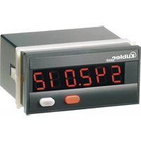
| Model | CODIX 520 |
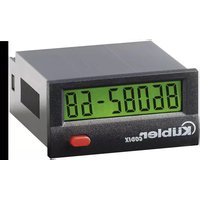
| Display | 6-decade red LED, height 8 mm |
| Display Range | 0 to 999,999 |
| Power Supply | 10...30 V DC, max. 55 mA |
| Max Counting Frequency | 60 kHz (at 24 V), 20 kHz (at 12 V), 8 kHz (at 10...30 V) |
| Counting Input | Dynamic, impedance 5 kΩ |
| RESET Input | Dynamic, min. pulse duration 5 ms |
| Programming | Via two front panel buttons, menu-guided |
| Input Filter | 30 Hz programmable |
| Input Polarity | NPN or PNP programmable |
| Decimal Point | Adjustable from 0 to 3 decimal places |
| RESET Mode | Manual, electrical or both (programmable) |
| Memory | EEPROM |
| Operating Temperature | -20 to +65°C (10...26 V), -20 to +55°C (>26...30 V) |
| Storage Temperature | -25 to +70°C |
| Protection Rating | IP65 (front panel) |
| Housing | 48 x 24 mm (front panel), cutout 50 x 25 mm |
| Weight | Approximately 50 g |
| EMC | Emission EN 55011 class B, Immunity EN 61000-6-2 |
| Cleaning | Soft damp cloth |
| Safety | Use only flush-mounted, disconnect before maintenance |
Frequently Asked Questions - CODIX 520 Kübler
User questions about CODIX 520 Kübler
0 question about this device. Answer the ones you know or ask your own.
Ask a new question about this device
Download the instructions for your Measuring equipment in PDF format for free! Find your manual CODIX 520 - Kübler and take your electronic device back in hand. On this page are published all the documents necessary for the use of your device. CODIX 520 by Kübler.
USER MANUAL CODIX 520 Kübler
- 6-digit adding counter with RESET function
- Red LED display, character height 8 mm
• Display range 0..999 999 - Leading zeros suppression
- Programming via two setting keys on the front side
- During programming, the display guides the user with text prompts
1.1 Safety instructions and warnings
Only use this display

– in a way according to its intended purpose
- if its technical condition is perfect
– adhering to the operating instructions and the general safety instructions.
1.2 General safety instructions
- Before carrying out any installation or maintenance work, make sure that the power supply of the digital display is switched off.
- Only use this digital display in a way according to its intended purpose:
If its technical condition is perfect. Adhering to the operating instructions and the general safety instructions. - Adhere to country or user specific regulations.
- The digital display is not intended for use in areas with risks of explosion and in the branches excluded by the standard EN 61010 Part 1.
- The digital display should only operate if it has been correctly mounted in a panel, in accordance with the chapter "Main technical features".
1.3 Use according to the intended purpose
The digital display may be used only as a panel-mounted device. Applications of this product may be found in industrial processes and controls, in manufacturing lines for the metal, wood, plastics, paper, glass, textile and other processing industries.
Over-voltages at the terminals of the digital display must be kept within the limits in Category II If the digital display is used to monitor machines or processes in which, in case of a failure of the device or an error made by the operator, there might be risks of damaging the machine or causing accidents to the operators, it is your responsibility to take appropriate safety measures.
2. Inputs
INP
Dynamic count input.
RESET
Dynamic RESET input. Linked in parallel to the red RESET key. Sets the counter to zero.
3. Setting of the operating parameters
a. Press both front side keys keys and switch on the supply voltage or, if the supply voltage is already on, press both keys simultaneously during 5 s.
b. The display shows

c. After releasing the keys, the display shows

c1. Hold the left key pressed and press the right key to leave the programming operation
c2. Press the right key to switch to

d. Hold the left key pressed and press the right key to switch to the first parameter.
e. After releasing the right keys, the display alternates between the menu title and the current menu item setting. After pressing down any key, only the menu item setting is displayed.
f. Pressing the right key, the menu item setting will be switched to the next value.
If figures are to be input (e.g. when setting the scaling factor), select first the digit using the left key, and then set the value using the right key.
g. Hold the left key pressed and press the right key to switch to the next menu item.
h. The last menu title "EndPro" allows, when selecting "Yes", to exit the programming menu
and to take over (store) the new values. If “no” is selected, the programming routine is repeated, the latest values set remaining active. They can now be checked aain or modified.
4. Programming routine
The programmable parameters of the device are described below, in succession. The device is fully programmed after one pass of the routine.
The first values stated correspond to the factory settings
4.1 Polarity of the inputs


npn: switching to 0 V
pnp: switching to +U_B
4.2 Switching on the 30 Hz filter (INP)
The filter provides input damping*

30 Hz filter off ( f_max )

30 Hzfilter on
4.3 Decimal point setting

The decimal point determines the way of displacing the count values. It does not affect counting.

0 no decimal place
0.0 one decimal place
0.00 two decimal places
0.000 three decimal places
4.4 RESET Mode


manual reset via the red RESET key and electrical reset via the RESET input

no reset (red RESET key and RESET input locked)

only electrical reset via the RESET input
only manual reset via the red RESET key
4.5 End of programming


The programming routine is repeated once more. The values set until now can be checked and modified.

The programming routine will be left and all values set will be stored as new parameters.
Afterwards the device is ready for operation.
5. Technical data
DC power supply: 10 ... 30 V DC/max. 55 mA with inverse-polarity protection
Display:
6 digits, red 7 segment LED display, height 8 mm
Data retention: EEPROM
Polarity of the inputs:
Programmable, npn or pnp for all inputs
Input resistance: appr. 5 kOhm
Couting frequency:
| DC power supply: | 24 V | 12 V | 10 ... 30 V |
| Input level: | Standard | 5 V | |
| typ. low level: 2,5 | V 2,0 V 1,0 V | ||
| typ. high level: | 22,0 V 10 V | 4,0 V | |
| Fmax:* | 60 kHz | 20 kHz 8 | kHz |
Minimum pulse length for the reset input: 5 ms
Input sensitivity:
Standard sensitivity:
DC power supply: Low: 0 ... 0,2 x UB [V DC] High: 0,6 x UB ... 30 V DC
4 ... 30 V DC level: Low: 0 ... 2 V DC High: 4 ... 30 V DC
Pulse shape: any*, Schmitt Trigger inputs
Ambient temperature:
-20 ... +65 °C at 10 ... 26 V DC
-20 ... +55 °C at >26 ... 30 V DC
Storage temperature:
$$ - 2 5 \dots + 7 0 ^ {\circ} \mathrm{C} $$
Altitude: to 2000 m
EMC:
Noise emission EN 55 011 Class B
Noise immunity EN 61 000-6-2
Housing: For front panel mounting
48 x 24 mm acc. to
DIN 43700,
RAL 7021, dark grey
Weight: appr. 50 g
Protection: IP 65 (front)
Cleaning: The front of the units is to
be cleaned only with a soft
wet (water!) cloth.
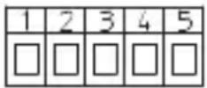
6. Terminal assignment
1 10 ... 30 V DC
20 V GND
3 INP
4 -
5 Reset
7. Ordering code
6.520.012.3X0

Input sensitivity
0 = Standard sensitivity
A = 4 ... 30 V DC level
8. Delivery includes:
1 Digital display
1 Panel mounting clip
1 Bezel for screw mounting, panel cut out 50 x 25 mm
1 Bezel for clip mounting, panel cut out 50 x 25 mm
1 Seal
1 Multilingual operating instructions
* at maximum frequency square wave pulses 1:1
9. Dimensions:
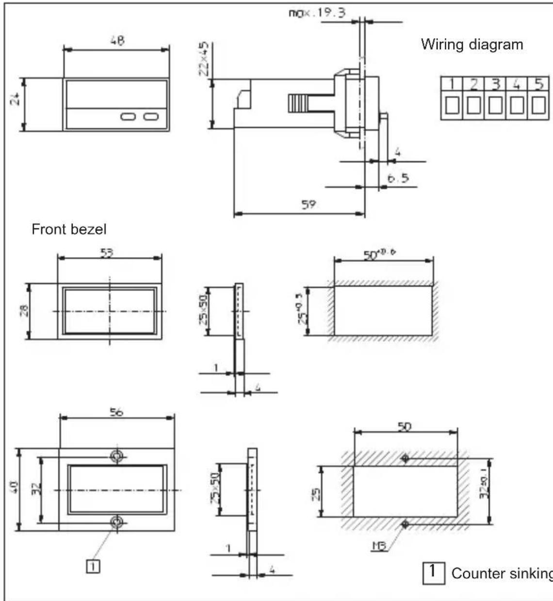
1 Counter sinking Af3, DIN 74
| Alimentazione CC: | 24 V | 12 V | 10 ... 30 V |
| Livello: | Standard | 5 V | |
| typ. Low: | 2,5 V | 2,0 V | 1,0 V |
| typ. High: | 22,0 V | 10 V | 4,0 V |
| Fmax:* | 60 kHz | 20 kHz | 8 kHz |
Fmax:* 60 kHz 20 kHz 8 kHz