TeleMate Pro TM700 - Measuring equipment Tempo - Free user manual and instructions
Find the device manual for free TeleMate Pro TM700 Tempo in PDF.
User questions about TeleMate Pro TM700 Tempo
0 question about this device. Answer the ones you know or ask your own.
Ask a new question about this device
Download the instructions for your Measuring equipment in PDF format for free! Find your manual TeleMate Pro TM700 - Tempo and take your electronic device back in hand. On this page are published all the documents necessary for the use of your device. TeleMate Pro TM700 by Tempo.
USER MANUAL TeleMate Pro TM700 Tempo
Read and understand all of the instructions and safety information in this manual before operating or servicing this tool.
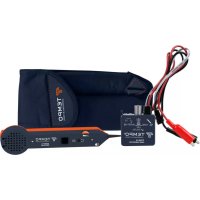
The Greenlee Communications TM-700 Tele-Mate® Pro Telephone Test Set is intended to assist with the installation and maintenance of complex telecom systems. A complete butt-in test set, the TM-700 adds useful features such as loudspeaker monitor, caller ID, speed dial, intercom, and line voltage/current/frequency meter.
The TM-700 not only works in handset mode, but can also be used with the standard headset (included) and with the amplified loudspeaker line monitor. Use the premium telco-type test leads and clips or the integral modular jack for line connection.
Features
- Complete telephone set with ringer
• Phone-to-phone intercom - Modular or alligator clip connection
- Amplified loudspeaker line monitor
- Headset or handset operation
- Tone and pulse dialing
• Large 10-location speed dialing memory - Multi-memory redial
- DTMF digit detection
- Tone output mode
- Caller ID with name display
- Call waiting caller ID
• Missed call indication - DSL compatible
- Glow-in-the-dark keypad
• Line voltage and current display
• High voltage detect and lockout
• High current detect and lockout
Key Specifications
• Bellcore and ETSI caller ID compatible
- User-selectable ANSI, ETSI, or custom telephone performance
• High voltage alert (110 VDC)
• High current alert (125 mA)
Safety
Safety is essential in the use and maintenance of Greenlee tools and equipment. This instruction manual and any markings on the tool provide information for avoiding hazards and unsafe practices related to the use of this tool. Observe all of the safety information provided.
Purpose of this Manual
This manual is intended to familiarize personnel with the safe operation and maintenance procedures for the TM-700 Tele-Mate® Pro Telephone Test Set.
Keep this manual available to all personnel. Replacement manuals are available upon request at no charge at www.greenlee.com.

Do not discard this product or throw away!
For recycling information, go to www.greenlee.com.
Important Safety Information

SAFETY ALERT SYMBOL
This symbol is used to call your attention to hazards or unsafe practices which could result in an injury or property damage. The signal word, defined below, indicates the severity of the hazard. The message after the signal word provides information for preventing or avoiding the hazard.
DANGER
Immediate hazards which, if not avoided, WILL result in severe injury or death.
WARNING
Hazards which, if not avoided, COULD result in severe injury or death.
CAUTION
Hazards or unsafe practices which, if not avoided, MAY result in injury or property damage.

WARNING
Read and understand this material before operating or servicing this equipment. Failure to understand how to safely operate this tool could result in an accident causing serious injury or death.

WARNING
Electric shock hazard: Contact with live circuits could result in severe injury or death.
WARNING
Electric shock hazard:
Environment: Do not use in wet conditions. Do not connect to network if apparatus is wet.
This device is rated to IP20.
Failure to observe this warning could result in severe injury or death.
All specifications are nominal and may change as design improvements occur. Greenlee Textron Inc. shall not be liable for damages resulting from misapplication or misuse of its products.
Tele-Mate is a registered trademark and SmartMute is a trademark of Greenlee Textron Inc.
KEEP THIS MANUAL
Important Safety Information

WARNING
When in Loudspeaker mode, hold loudspeaker more than 30 cm (1 foot) from your ear.
Misuse could result in hearing damage.
WARNING
Electric shock hazard:
Before opening the case, remove the test leads from the circuit and shut off the unit.
Failure to observe this warning could result in severe injury or death.
CAUTION
- This unit is to be used by trained personnel only.
- Do not perform any service or maintenance other than as instructed in this manual.
Failure to observe these precautions may result in injury or property damage.
CAUTION
- Inspect the test set and cord for wear or damage. Replace worn, damaged, or missing components with Greenlee replacement parts. A damaged component may fail, resulting in injury or property damage.
- If the equipment is used in a manner not specified by the manufacturer, the protection provided by the equipment may be impaired.
IMPORTANT
Replace weak or discharged batteries as soon as either of these conditions is detected.
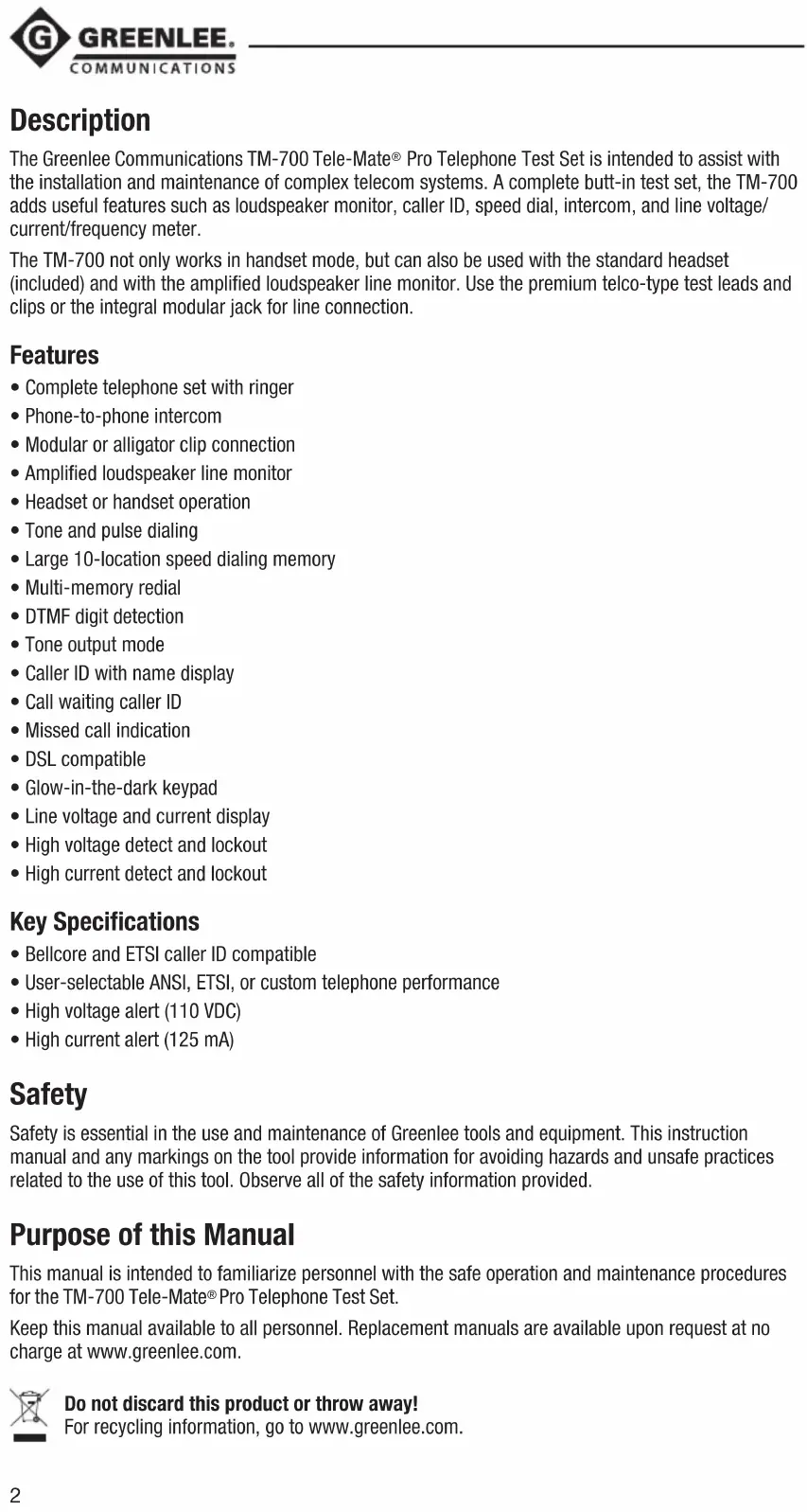
Identification

MONITOR / TALK Switch

MUTE Button

Volume Control Switch
Setup
Battery Installation
WARNING
Electric shock hazard:
Before opening the case, remove the test leads from the circuit and shut off the unit.
Failure to observe this warning could result in severe injury or death.
The TM-700 requires two AA batteries to be installed for all functions to operate. Greenlee recommends alkaline batteries, which are more leak resistant and offer much longer operating life than standard zinc-carbon types.
When a battery is first installed, the unit will default to a Language Setup display (Figure 1). Select a language before using the unit.
To access the battery compartment, loosen the screw located at the top of the unit and slide the battery cover out. Insert the new alkaline batteries, carefully checking that the polarity is correct before replacing the cover and re-tightening the screw. (Do not overtighten the screw.)
Low Battery Warning
When the battery voltage becomes low, a warning sound is produced each time the mode switch position changes. In addition, a small battery icon is displayed in the lower left of the screen. If the battery voltage is allowed to drop below a critical level, the unit will remind you to replace the battery for a few seconds and then return to standby mode.
Reset
The TM-700 should start operating normally following battery insertion or replacement. If the unit fails to respond normally at any time, perform a manual reset by holding (dower) down for more than 10 seconds. The unit should then start as normal, provided the battery voltage is ok.
Operation
The TM-700 test set has six main operating modes: Setup, Talk, Monitor, DTMF Detection, Toner, and Intercom.
Setup Mode
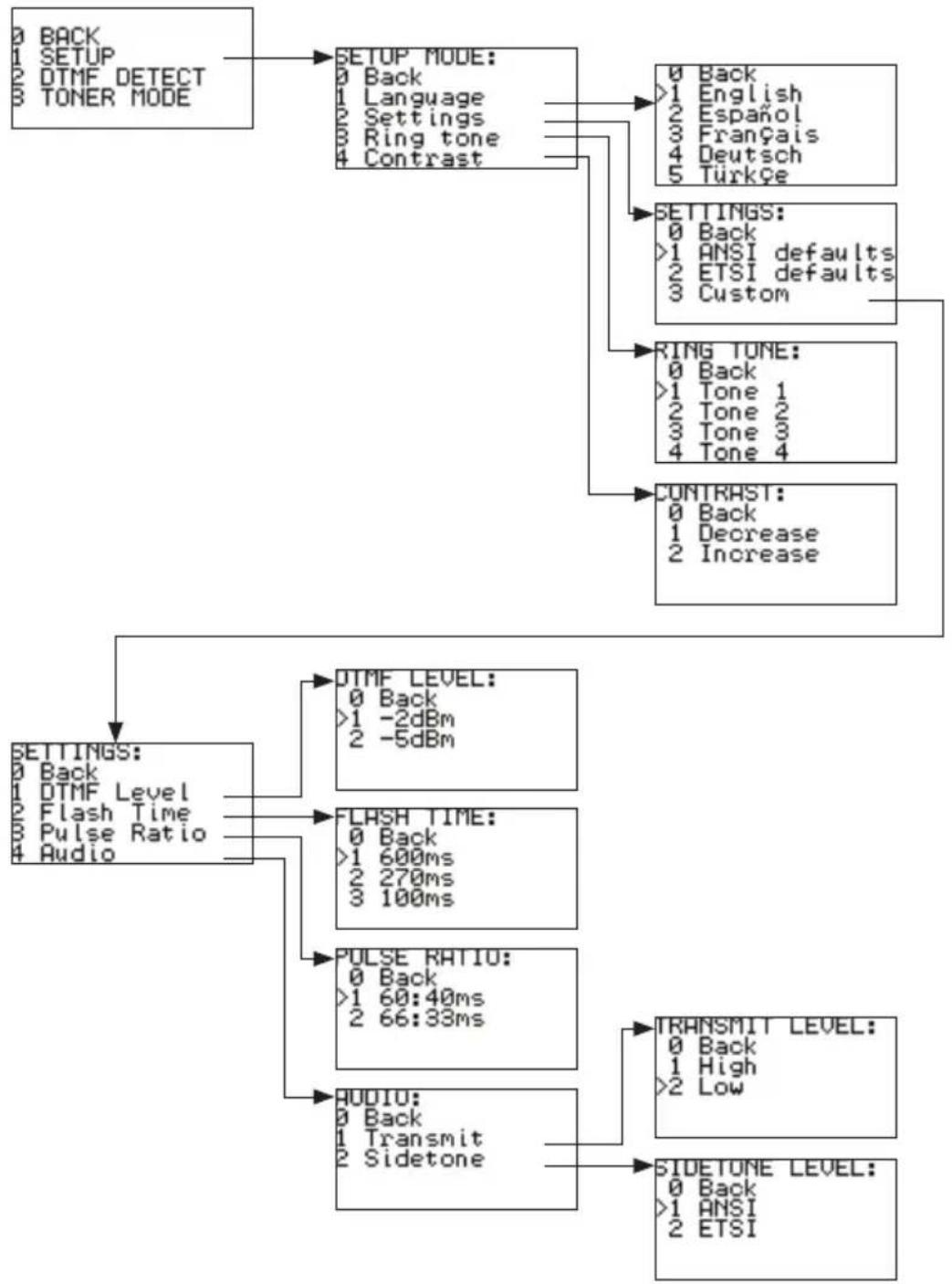
With the mode switch set to MONITOR, simultaneously press and # . The unit then enters the special features mode. While in this menu, select option 1 to access Setup mode. Now the language and other configurable settings can be set up.
Press the digit corresponding to the desired option to choose it.
To leave this mode, press 0 (back) repeatedly. An invalid entry will result in an error tone.
flowchart
graph TD
    A["0 BACK\n1 SETUP\n2 DTMF DETECT\n3 TONER MODE"] --> B["SETUP MODE:\n0 Back\n1 Language\n2 Settings\n3 Ring tone\n4 Contrast"]
    B --> C["0 Back\n1 English\n2 Español\n3 Français\n4 Deutsch\n5 Türkçe"]
    B --> D["SETTINGS:\n0 Back\n1 ANSI defaults\n2 ETSI defaults\n3 Custom"]
    D --> E["RING TONE:\n0 Back\n1 Tone 1\n2 Tone 2\n3 Tone 3\n4 Tone 4"]
    D --> F["CONTRAST:\n0 Back\n1 Decrease\n2 Increase"]
    F --> G["SETTINGS:\n0 Back\n1 DTMF Level\n2 Flash Time\n3 Pulse Ratio\n4 Audio"]
    G --> H["DTMF LEVEL:\n0 Back\n>1 -2dBm\n2 -5dBm"]
    G --> I["FLASH TIME:\n0 Back\n>1 600ms\n2 270ms\n3 100ms"]
    I --> J["PULSE RATIO:\n0 Back\n>1 60:40ms\n2 66:33ms"]
    J --> K["AUDIO:\n0 Back\n1 Transmit\n2 Sidetone"]
    K --> L["TRANSMIT LEVEL:\n0 Back\n1 High\n>2 Low"]
    L --> M["SIDETONE LEVEL:\n0 Back\n>1 ANSI\n2 ETSI"]
Figure 1.
Talk Mode
CAUTION
This device is for connection to TNV3 network voltages only. Use this unit only on standard analog Telecom networks.
With the main mode switch in the TALK position and connected to a suitable telephone line, the unit will go off-hook. Dialing and speech are now possible.
Flash
While off-hook, the Flash key is enabled. This key generates a timed line break, which simulates a hook flash to activate special features of a PBX or central office (Figure 2).
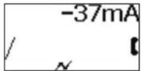
Figure 2.
The flash duration is user-selectable via the Setup mode as 100 ms, 270 ms, or the default of 600 ms. The symbol is present on the bottom line of the display during Flash operation and for 2 seconds afterward.
Off-Line Dialing and Automatic Redial of Last CID Number
Digits entered by hand or received by calling line ID in Monitor mode are dialed automatically upon switching to TALK. Any displayed number can be cleared by pressing and holding MUTE for 1 second. Short presses of MUTE act as a backspace, allowing errors to be corrected before switching to TALK to dial.
O/II Pause
The dual function LNR/Pause key inserts an inter-digit delay of 3 seconds between digits dialed. The pause digit is displayed as “—” (minus sign) on the LCD and is stored in memory. Note that if this were the first key pressed, this would recall and immediately dial LNR (see “Memory Functions”).
Pulse Dialing Option
To make a call using pulse dialing, press the Pulse key to select Pulse mode. Then either dial or recall from memory the number to be called. The symbol is displayed on the bottom line of the display. Press the Pulse key again to revert to Tone mode. The dialing mode is also changeable from Pulse to Tone while dialing by pushing the Pulse, or # keys. Such mid-call transitions of dialing mode are stored and shown as F in the stored digit sequence, indicating the requested change to Tone mode (Figure 3).
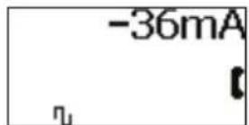
Figure 3.
Current Measurement
While the TM-700 is off-hook, the line current is displayed along with the polarity.
Over Current Protection
When the TM-700 is off-hook, it protects against line current over 125 mA by automatically applying a current limit. If the condition is maintained for more than about half a second, the unit goes on-hook, a warning message is displayed, and a warning sound is produced until the unit is disconnected from the line or switched off (Figure 4).
Figure 4.
SmartMute™
A quick press of the MUTE button toggles the microphone off or on. A long press (over 1 second) mutes the microphone while the button is held. The mute symbol ☒ is displayed while the microphone is deactivated.
Loudspeaker
Press the Loudspeaker key at any time in Monitor or Talk modes to turn the speaker on or off. Note that the microphone is automatically muted if you are in Talk or Intercom modes, and 📄 is displayed whenever the speaker is active to remind you that two-way speech is not possible. The speaker remains on for the whole duration of a call, and is kept on while switching to another mode. Automatic power-down turns the speaker off (see “Automatic Power Down” below).
Volume Control
Slide switch to 1, 2, or 3 to satisfy earpiece volume level requirements.
Monitor Mode
With the main mode switch in the MONITOR position, the unit will be on-hook. This mode provides a high impedance connection that enables the user to listen to the line without loading it (Figure 5).
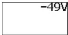
Figure 5.
Monitor mode also constantly monitors and displays the line voltage along with the polarity. With the red lead attached to ring and black to tip, the display shows negative “—” voltage. In the presence of incoming ring, the display provides line status information with caller ID if present, and a ringing alert signal is produced from the loudspeaker.
DTMF Detection Mode
To enter DTMF Detection mode, press * and # simultaneously while in Monitor mode, and then select option 2 from the menu.
This mode detects the DTMF tones generated by another unit when it is actively dialing. This mode can also be used to check incoming DTMF caller ID pattern.
Toner Mode
To enter Toner mode, press* and # simultaneously while in Monitor mode, and then select option 3 from the menu.
This mode transmits a tracing tone at the line terminals, which is compatible with Greenlee's filter probe key frequencies. Two different speed cadence tones are selectable by selecting 1 or 2 in the Toner menu.
Over Voltage Warning
The unit is protected against operating in Talk mode when voltages exceed 110 V. A warning tone will be generated and the screen will display the message "Over-voltage!" (Figure 6).

Figure 6.
Elevated Voltage Warning
If the unit is connected to a voltage between 80 V and 110 V, high-pitched beeps will be produced, warning that this is probably not a normal telephone line (Figure 7). This audible alarm can be disabled by pressing the MUTE button. You can also go off-hook by moving the mode switch to the TALK position.
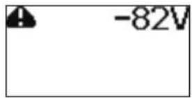
Figure 7.
Answering Incoming Call
While the TM-700 is ringing, move the mode switch to the TALK position.
Note: The TM-700 will not allow off-hook if ringing is continuous. Check the frequency reported on the screen; if the frequency is approximately 50 Hz to 60 Hz, carefully disconnect from the line.
Automatic Power Down
To extend battery life, the TM-700 powers down after periods of no user interaction in all modes, except active Talk mode.
• Talk mode with no DC detected: 5 minute timeout
- Talk mode with DC detected: No timeout
• Intercom mode: 60 minute timeout
• Monitor mode: 15 minute timeout
The TM-700 can be re-activated following a timeout by pressing (power) or connecting to DC (powered line).
Intercom (Local Battery) Mode
The Intercom mode is a feature that allows two TM-700 test sets to communicate without any telephone service available. In this mode only speech signals pass over the telephone pair, and no DC power (talk battery) is available. The SmartIntercom feature only works with other TM-700 test sets. The intercom feature only works if there is no voltage on the line (Figures 8–10).
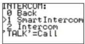
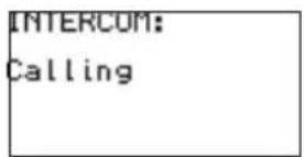

Figure 8. Figure 9. Figure 10.
To activate either Intercom mode, start with the mode switch in MONITOR position and press the Flash key. You will be presented with the menu shown in Figure 8; by default SmartIntercom will be selected.
To begin the call and ring the far end, slide the mode switch to TALK.
If you are making a SmartIntercom call, when the distant unit recognizes the call request you will hear a regular ring-back tone from the earpiece. If there is no reply from the distant unit, after a few seconds you will hear an error beep.
Incoming SmartIntercom call alerts will be received in either Off or Monitor mode; you do not need to be in Intercom mode to receive the alerting signal.
The intercom-alerting signal (ring tone) is a fast cadenced, higher pitched ring than normal. If this is heard, then simply switch to Talk mode to answer the call, automatically placing the TM-700 into Intercom mode. A confirmation beep is produced to indicate that the Intercom mode is now active.
To leave Intercom mode, simply move the mode switch from TALK to MONITOR. A call-completed tone is sent down the line as you do this to alert the other user.
Memory Functions
Memory and store facilities are available in Talk and Monitor modes. There are 10 memory locations for number storage and a multi-number “last number redial” store. These can be accessed as described below.

Last Number Redial
When in Monitor mode, the Redial key offers the user the ability to recall any of the last 10 numbers dialed or received by CLID on the unit. The numbers can be accessed by repeatedly pressing the Redial key with number information displayed on the LCD. This number will be automatically dialed out when the switch is placed back to the Talk mode (Figure 11).
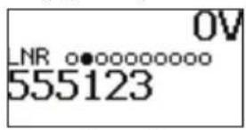
Figure 11.
In Talk mode the Redial key offers the last number dialed (or last CLID) only if no other digits have already been dialed. After dialing any digits, this key becomes the Pause key.

Saving Speed Dial Number
Enter a number or leave an incoming ID message on the screen. Push the Memory key twice to enter the store mode, and then enter the key number (0–9) to save the number to a memory location (Figures 12–14).
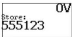
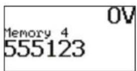
Figure 12. Figure 13. Figure 14.

Recall Speed Dial Number
Push the Memory key once followed by the key number (0–9) (Figures 15–17). In addition to direct access by pressing the corresponding number while on-hook in Monitor mode, repeatedly pressing the Memory key allows you to scroll sequentially through all 10 stored numbers. In all cases the number remains displayed, allowing automatic dialing by simply switching to TALK.
Note: If a location recalled is unused, then no number will be displayed.
Figure 15. Figure 16. Figure 17.
Caller ID
CID and CIDCW information will be displayed in Monitor and Talk modes, when available. Error messages are displayed when the CID is detected but not received in full, is corrupted, or is of an incompatible type (Figures 18–19).

Figure 18. Figure 19.
Headset
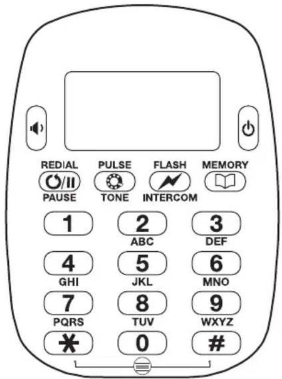
To use the TM-700 hands-free, simply plug the supplied headset into the socket at the bottom of the unit (see "Identification"). This will automatically mute the internal earpiece and microphone. Note that the MUTE and Speaker buttons will operate as normal, i.e., will disable transmission when active.
Specifications
Telephone Compatibility: TIA/EIA-470-B and ETSI
Storage Temperature: -10 °C to +70 °C (14 °F to 158 °F)
Operating Temperature: 0 °C to +50 °C (32 °F to 122 °F)
Humidity: Up to 90% operating, 95% storage, both with no condensation
CID and CIDCW: Bellcore TR-NWT-000030 (GR30) and SR-TSV-002476
Battery Life: Over 6 months of typical use; only alkaline types recommended; remove batteries if storing unit for long periods
Loop Limits (at 48 V):
Resistance: >5 kΩ
Minimum Current: <10 mA
DC Resistance:
Off-hook: <300 Ω
On-hook: >10 MΩ
Monitor Impedance: >400 kΩ
Pulse Dialing:
Rate: 10 pps or 20 pps
Break: 60% or 66%
Inter-digit Pause: 800 ms (leakage during break >1 M)
DTMF/Tone: -4 dBm / -6 dBm (ANSI); -9 dBm / -11 dBm (ETSI)
FSK Caller Name/Number and Call Waiting:
Bellcore GR-30-CORE, TR-NWT-000030
ETSI FSK types
Displays: Called DN, Caller name
Soft Key Function (on two context-sensitive keys):
Flash/Timed Break Recall: 100 ms, 270 ms, 600 ms
Memory Dialing: 10 memories, 10 LNR
Indicators:
LCD (96 x 48 pixels, 5 lines) displays the following:
Caller ID (name and number) and Call Waiting
Dialed number
Over-voltage conditions
Phone status (monitor, on hook etc.)
Line Voltage: 110 Vdc max
Loop Current: 125 mA max
Ring Frequency: 15–70 Hz
Line Protection:
Over-voltage: 360 Vdc continuous >500 V peak
Current Limited: 125 mA
Lightning: ITU K.17, 20, 21 (1500 V)
Intercom Range: 6 km
Toner Output: 7 V pk-pk (square wave)
Maintenance
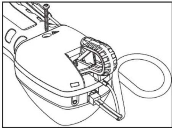
Changing Line Cord
- Disconnect the unit from the circuit.
- Remove the screw and slide the cover off.
natural_image
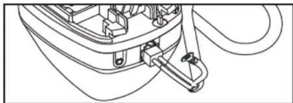
Technical line drawing of a mechanical device with attached components (no text or symbols)- Disconnect the strain relief.
natural_image
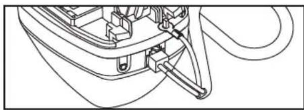
Technical line drawing of a mechanical component with no visible text or symbols- Replace the line cord and reconnect the strain relief.
- Slide the cover back on and tighten the screw.
natural_image
Technical line drawing of a mechanical component with no visible text or symbolsCleaning
For cleaning it is recommended to only use a cloth dampened with a solution of soap and water.
Glossary
On-hook / Monitor: The phone line is available for listening only.
Off-hook / Talk: The phone is activated.
Line Current: The amount of current fed from the telephone line when off hook, in milliamperes (mA).
Flash: A momentary line current break used by the butt set to signal the phone system for special function.
Descripción
ADVERTENCIA
natural_image
Technical line drawing of a mechanical device with attached components (no text or symbols)natural_image
Technical line drawing of a mechanical component with no visible text or symbolsnatural_image
Technical line drawing of a mechanical assembly with no visible text or symbolsLimpieza
▲AVERTISSEMENT
Figure 12. Figure 13. Figure 14.
natural_image
Technical line drawing of a mechanical device with attached components (no text or symbols)natural_image
Technical line drawing of a mechanical component with no visible text or symbolsnatural_image
Technical line drawing of a mechanical assembly with no visible text or symbolsNettoyage
⚠️WARNUNG
Blitze: ITU K.17, 20, 21 (1500 V)
natural_image
Technical line drawing of a mechanical device with attached components (no text or symbols)natural_image
Technical line drawing of a mechanical component with no visible text or symbolsnatural_image
Technical line drawing of a mechanical component with no visible text or symbolsReinigung
One-Year Limited Warranty
Greenlee Textron Inc. warrants to the original purchaser of these goods for use that these products will be free from defects in workmanship and material for their useful life, excepting normal wear and abuse.
For all Test Instrument repairs, you must first request a Return Authorization Number by contacting our Customer
Service department at: toll free in the US and Canada 800 642-2155; Telephone +1 760 598-8900;
Facsimile +1 760 598-5634.
This number must be clearly marked on the shipping label.
Ship units Freight Prepaid to: Greenlee Repair Center, 1390 Aspen Way, Vista CA 92081 USA.
Mark all packages: Attention: TEST INSTRUMENT REPAIR.
For items not covered under warranty (such as dropped, abused, etc.) repair cost quote available upon request.
Note: EMEA users—contact Greenlee Communications Ltd., Brecon House, William Brown Close, Cwmbran, NP443AB, UK +44 1633 627 710.
Cwmbran, NP44 3AB, UK +44 1633 627 710.
Greenlee Repair Center, 1390 Aspen Way, Vista, CA 92081 USA
An ISO 9001 Company • Greenlee Textron Inc. is a subsidiary of Textron Inc.
USA
Tel: 800-435-0786
Fax: 800-451-2632
Canada
Tel: 800-435-0786
Fax: 800-524-2853
International
Tel: +1-815-397-7070
Fax: +1-815-397-9247
Europe, Middle East, Africa, Asia & Pacific
Greenlee Communications Ltd.
Brecon House • William Brown Close • Cwmbran, NP44 3AB • UK
Tel: +44 1633 627 710 • EMEAsales@greenlee.textron.com