NC100 - Measuring equipment Tempo - Free user manual and instructions
Find the device manual for free NC100 Tempo in PDF.
| Product Type | Network/Coaxial/Phone Cable Tester |
| Brand | Tempo |
| Model | NC100 (Micro NETcat) |
| Category | Measuring Equipment |
| Dimensions | 150 x 70 x 33 mm |
| Weight | 220 g (with remote unit and battery) |
| Power Supply | 9 V alkaline battery (type PP3, 6LR61) |
| Display | High contrast LCD with green LED backlight (icons and 7-segment) |
| Main Functions | Continuity check, short circuit detection, reverse polarity, crossed pairs, split pairs |
| Test Modes | Network (Ntwk), Telephone (Tel), Coaxial (Coax) |
| Cable Tracing | 3 selectable tones (HiLo1, HiLo2, HiLo3) |
| Connectors | Shielded RJ45, RJ12 6-pin, female F-type coaxial |
| Operating Temperature | 0 °C to 50 °C |
| Storage Temperature | -10 °C to 60 °C |
| Humidity | Up to 95% non-condensing |
| Cleaning | Damp cloth and mild detergent (no abrasive products or solvents) |
| Safety Instructions | Do not connect to AC circuits; do not repair; avoid extreme temperatures/humidity |
| Warranty | Limited 1-year warranty |
| Included Accessories | Remote unit |
| Manual Language | French (other languages available) |
Frequently Asked Questions - NC100 Tempo
User questions about NC100 Tempo
0 question about this device. Answer the ones you know or ask your own.
Ask a new question about this device
Download the instructions for your Measuring equipment in PDF format for free! Find your manual NC100 - Tempo and take your electronic device back in hand. On this page are published all the documents necessary for the use of your device. NC100 by Tempo.
USER MANUAL NC100 Tempo
natural_image
Abstract geometric logo with a black diamond containing a white letter 'G' in the center (no text or symbols beyond the emblem)GREENLEE®
A Textron Company

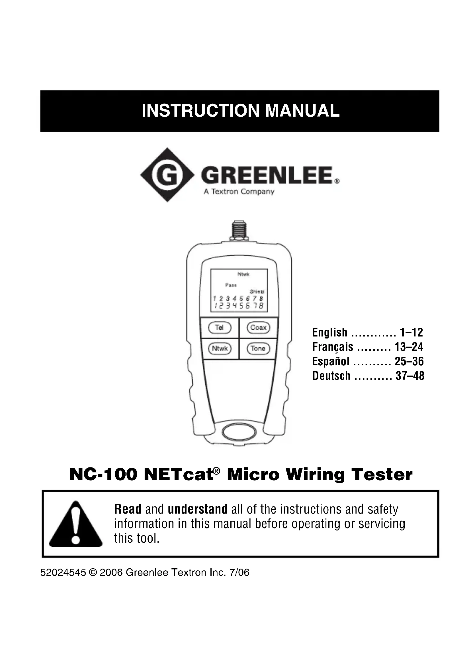
English 1–12
Français ..... 13–24
Español ..... 25–36
Deutsch ..... 37–48
NC-100 NETcat® Micro Wiring Tester

Read and understand all of the instructions and safety information in this manual before operating or servicing this tool.
Description
The NETcat® Micro wiring tester is a device that verifies twisted pair and coaxial cables. It uses high-speed digital technology to check wiring continuity and correct allocation of wire pairs.
Additional features include the following:
- Employs a high-contrast LCD with backlight.
- Tests shielded twisted pair (STP), unshielded twisted pair (UTP), and coaxial cables.
- Generates three distinct tones for cable tracing.
- Verifies wiremaps.
- Detects shorts, opens, reversed polarity, crossed pairs, and split pairs.
Safety
Safety is essential in the use and maintenance of Greenlee tools and equipment. This instruction manual and any markings on the tool provide information for avoiding hazards and unsafe practices related to the use of this tool. Observe all of the safety information provided.
Purpose of This Manual
This instruction manual is intended to familiarize all personnel with the safe operation and maintenance procedures for the Greenlee NC-100 NETcat® Micro. Keep this manual available to all personnel. Replacement manuals are available upon request at no charge.
All specifications are nominal and may change as design improvements occur. Greenlee Textron Inc. shall not be liable for damages resulting from misapplication or misuse of its products.
NETcat is a registered trademark of Tempo Research Corp.
Important Safety Information

SAFETY ALERT SYMBOL
This symbol is used to call your attention to hazards or unsafe practices which could result in an injury or property damage. The signal word, defined below, indicates the severity of the hazard. The message after the signal word provides information for preventing or avoiding the hazard.
DANGER
Immediate hazards which, if not avoided, WILL result in severe injury or death.
WARNING
Hazards which, if not avoided, COULD result in severe injury or death.
CAUTION
Hazards or unsafe practices which, if not avoided, MAY result in injury or property damage.
Important Safety Information

natural_image
Illustration of a hand pointing at an open book with visible pages (no text or symbols)WARNING
Read and understand this material before operating or servicing this equipment. Failure to understand how to safely operate this tool could result in an accident causing serious injury or death.
WARNING
Electric shock hazard:
Do not connect this unit to AC power circuits.
Failure to observe this warning could result in severe injury or death.
Important Safety Information
CAUTION
Electric shock hazard:
- Using this unit in a high frequency activated area may result in unstable or inaccurate readings.
- Do not drop or get the unit wet as it may cause internal damage.
- Do not attempt to repair this unit. It contains no user-serviceable parts.
- Do not expose the unit to extremes in temperature or humidity. Refer to “Specifications.”
- Use this unit for the manufacturer's intended purpose only, as described in this manual. Any other use can impair the protection provided by the unit.
Failure to observe these precautions may result in injury and can damage the unit.
CAUTION
Electric shock hazard:
This unit is capable of withstanding voltage input conditions when connected to normal telephony equipment (i.e., 50 VDC) for short periods. Testing is inhibited when greater than a few volts is connected across a pair with the message shown here displayed on the screen. Disconnect the unit immediately to prevent permanent damage.
VOLTS!
Failure to observe this precaution may result in injury and can damage the unit.
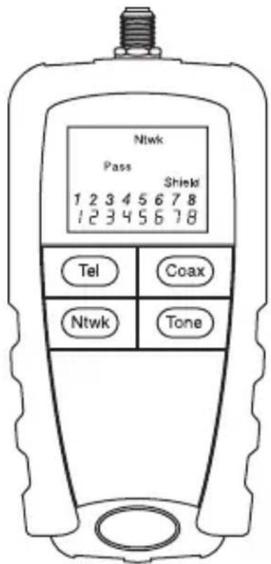
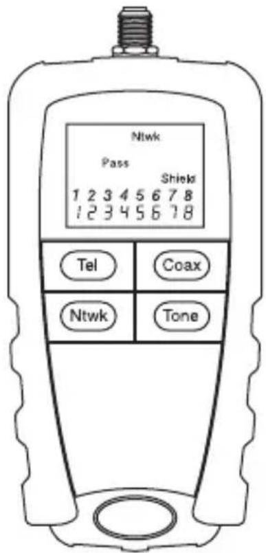
LCD Icons
The unit's interface employs a high-contrast, backlit LCD panel to aid ease of use. The icons are used in the following way:
- Tel, Coax, Ntwk: Telephone, Coaxial, or Network test mode is selected.
- Tone: Pair Tracing Tone is active.
- Reversed: Polarity of telephone pair is reversed.
- Battery is low.*
- Miswire: Wiring is not one-to-one.
-
Shield: Shield or screen is connected.
-
Short: Some wires are short circuit.
-
Digits showing wiremapping to remote unit.
-
Open: Some wires are open circuit.
-
Pass: All wires are connected one-to-one (correct).
-
Split: Split pair is detected.
-
VOLTS!: Voltage is detected on one or more pairs; testing is inhibited. Disconnect quickly to prevent damage.
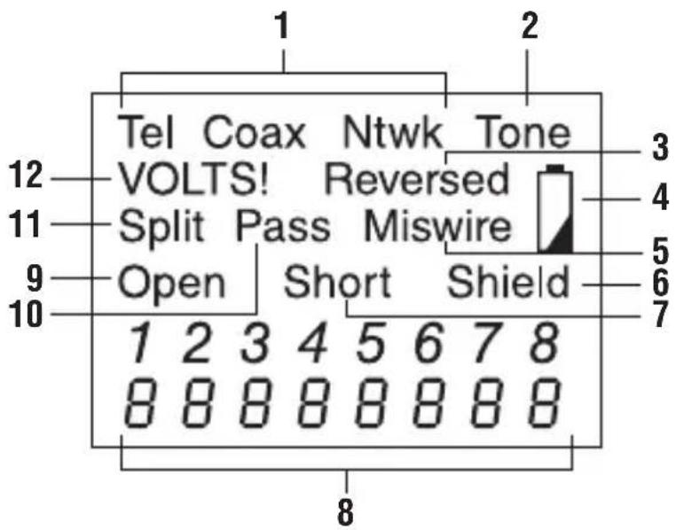
* The NETcat Micro requires one 9 V snap-type battery (alkaline types are recommended). When the low battery icon is displayed, a few hours of typical use remain. Using the unit with a low battery will eventually affect the accuracy of measurements.
Operation
Switch ON, OFF, and Auto-Off
- To switch the NETcat Micro unit on, press the desired mode button for half a second.
- To switch the unit off, press a different mode button for half a second.
- To extend battery life, the unit will switch itself off after approximately 5 minutes without any button being pressed. The unit will not switch off in Tone mode.
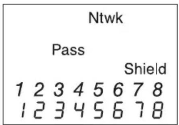
Network Cable Test (Ntwk)
Network test mode allows the user to check typical RJ45 cables, such as CAT5 or similar specification including shielded types, for correct wiring.
- Connect the remote unit using a short patch lead (previously tested) at one end of the cable to be checked and the NETcat Micro at the other end.
- Press Ntwk. The unit immediately checks for the presence of voltages. If none are found that may interfere with testing or damage the unit, tests are carried out to check the wiring of the pairs of the cable and, if present, the shield of the cable.
- Check the icons on the display. If the cable is miswired so that wires of different pairs are used where true pairs should be used, the "Split" icon will be set. Note that splits may only be detected in cables over 2 m (5 ft) in length. Note also that split pair detection may be switched off by pressing and holding Ntwk for 2 seconds if you wish to ignore split indications given for non-standard wiring systems. The default mode is "Split On".
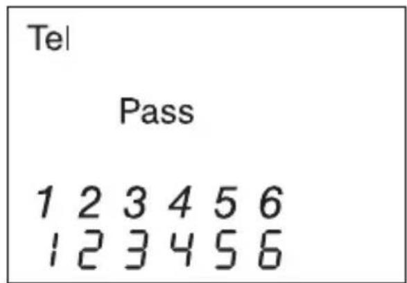
Telephone Cable Test (Tel)
As above, but for cables of up to three pairs wired to the RJ12 socket. One additional test is done in this mode where pairs with reversed polarity are identified and the “Reversed” icon will be set if this is the case. There is no shield continuity test in this mode.
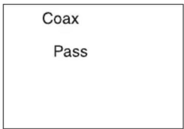
Coaxial Cable Test (Coax)
As above, but for one pair (i.e., coaxial cables).
Test Details
Voltage Checks
This test checks for a voltage in excess of a few volts DC across each pair. If a voltage is detected above this threshold, then testing will be inhibited.
Wiremap
This test checks the cable for correct wiring when the remote unit is connected to the end of the cable under test. The cable configuration is tested for shield continuity (if fitted), opens, shorts, reversed pairs, crossed pairs, and split pairs. Below are examples of detectable faults along with a good wiremap.
Examples of Common Results
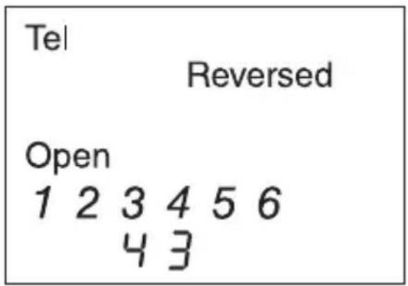
Simple RJ11 Telephone Cord
This screen shot shows how a simple RJ11 to RJ11 connection lead is tested. As the plugs are connected the “same way up” either end of the cable, there is effectively a polarity reversal. And as only a single pair is connected, the other pairs (2/5 and 1/6) are open.
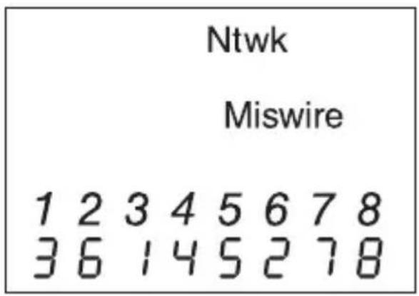
CAT5 Crossover Cable
This screen shot shows how a typical two-pair crossover cable is often used to connect devices back to back, with the pairs 1/2 and 3/6 swapped. This is still shown as a “Miswire” as the only condition to allow the “Pass” icon to be set is a perfect straight through cable. As there are several different types of crossover cable currently in use, it was decided to show the condition and allow the user to decide if the result is what you require in your specific application
Tracing Tone Mode
This function provides a means of tracking cables by generating one of three distinct selectable tones on a specific wire, pair, or all pairs. The cable can be traced using a tracing probe that is capable of detecting tones ranging from 577 Hz to 983 Hz.
The three available tones are as follows:
- HiLo1 – Fast Warble
- HiLo2 – Medium Warble
- HiLo3 – Slow Warble
To select the relevant Tracing Tone mode, first select the cable type by switching the unit on in Network, Telephone, or Coaxial mode. Then press Tone to activate the tracing tones. Repeated quick presses of Tone will allow you to select which wires or pairs are carrying the tone depending upon mode. A long press of Tone (more than 2 seconds) will select the next type of tone, "HiLo1", "HiLo2" or "HiLo3".
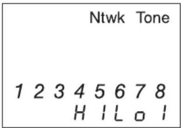
This screen shows, for example, that all wires of a network cable are carrying the "HiLo1" tone.
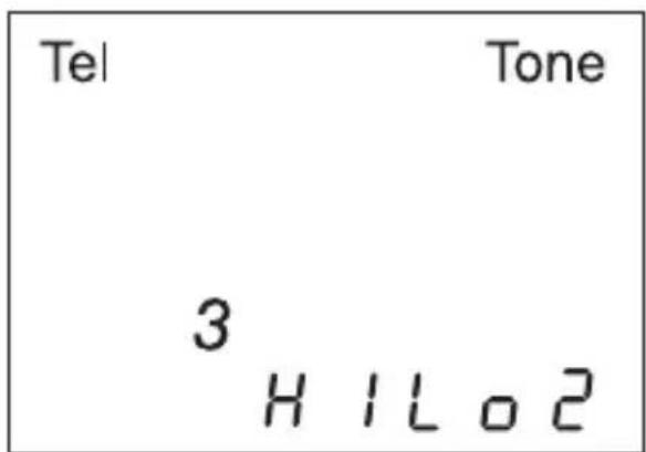
In this screen only wire "3" of the telephone cable is carrying the "HiLo2" tone.
Specifications
Dimensions: 150 mm x 70 mm x 33 mm (5.9" x 2.75" x 1.3")
Weight: 220 g (0.5 lb) (including remote unit and a typical battery)
Power Source: 9 V alkaline battery (PP3, 6LR61)
User Interface:
Display LCD: Icon and seven-segment type, mixed
Backlight: Green LED
Buttons: Four momentary contact push buttons
Environmental: Designed for use in a typical indoor environment where typical IT equipment may be found.
Operating Temperature: 0 °C to 50 °C (32 °F to 122 °F)
Storage Temperature: -10 °C to 60 °C (14 °F to 140 °F)
Humidity: Up to 95% non-condensing
Interface Connections:
RJ45 shielded socket
RJ12 6-way socket
F-Type threaded female coaxial
Minimum Cable Length for Network Split Pair Detection: 2 m to 3 m (5 ft to 10 ft) depending upon cable type
Pair Tracing Tones: Alternating frequencies of 577 Hz and 983 Hz are produced at three user-selectable rates
Pair Connection Assumptions: It is assumed when testing telephone and network cables that the allocation of pairs to circuit numbers is in accordance with TIA standards, i.e.:
Network Mode: 1 & 2, 3 & 6, 4 & 5, 7 & 8
Telephone Mode: 1 & 6, 2 & 5, 3 & 4
Maintenance
CAUTION
Electric shock hazard:
- Do not attempt to repair this unit. It contains no user-serviceable parts.
- Do not expose the unit to extremes in temperature or humidity. Refer to “Specifications.”
Failure to observe these precautions may result in injury and can damage the unit.
Battery Replacement
- Loosen the screw to open the battery compartment door.
- Replace the batteries (observe polarity).
- Close the battery compartment door.
Cleaning
Periodically wipe the housing with a damp cloth and mild detergent; do not use abrasives or solvents.
One-Year
Limited Warranty

natural_image
Abstract geometric logo with a white diamond containing a black circle containing the letter 'G' (no text or symbols beyond the design)GREENLEE®
A Textron Company
USA 800-435-0786
815-397-7070
Fax:
800-451-2
Fax:
81
Canada 800-435-0786
Fax:
800-524-2853
International +1-815-397-7070
Fax: +1-815-397-9247
4455 Boeing Drive • Rockford, IL 61109-2988 • USA • 815-397-7070
An ISO 9001 Company • Greenlee Textron Inc. is a subsidiary of Textron Inc.
www.greenlee.com
MANUEL D'INSTRUCTIONS

natural_image
Abstract geometric logo with a black diamond containing a white letter 'G' in the center (no text or symbols beyond the emblem)GREENLEE®
A Textron Company
natural_image
Illustration of a hand interacting with an open book (no text or symbols visible)▲ AVERTISSEMENT
Utilisation
Test de câble coaxial (Coax)
natural_image
Abstract geometric logo with a stylized letter 'G' inside a diamond shape (no text or symbols)GREENLEE®
A Textron Company
USA 800-435-0786 Fax: 800-451-2
815-397-7070 Fax: 81
Canada 800-435-0786 Fax: 800-524-2853
International +1-815-397-7070 Fax: +1-815-397-9247
4455 Boeing Drive • Rockford, IL 61109-2988 • USA • 815-397-7070
An ISO 9001 Company • Greenlee Textron Inc. is a subsidiary of Textron Inc.
www.greenlee.com
natural_image
Abstract geometric logo with a stylized letter 'G' inside a diamond shape (no text or symbols)GREENLEE®
A Textron Company
natural_image
Illustration of a hand pointing at an open book with visible pages (no text or symbols)ADVERTENCIA
natural_image
Abstract geometric logo with a white diamond containing the letter 'G' in black and white (no text or symbols beyond the graphic)GREENLEE®
A Textron Company
| USA | 800-435-0786 | Fax: | 800-451-2 |
| 815-397-7070 | Fax: | 81 | |
| Canada | 800-435-0786 | Fax: | 800-524-2853 |
| International | +1-815-397-7070 | Fax: | +1-815-397-9247 |
4455 Boeing Drive • Rockford, IL 61109-2988 • USA • 815-397-7070
An ISO 9001 Company • Greenlee Textron Inc. is a subsidiary of Textron Inc.
www.greenlee.com
BEDIENUNGSANLEITUNG

natural_image
Abstract geometric logo with a black diamond containing a white letter 'G' (no text or symbols beyond the emblem)GREENLEE®
A Textron Company

NC-100 NETcat® Micro Verdrahtungstester

natural_image
Illustration of a hand pointing at an open book with visible pages (no text or symbols)⚠️WARNUNG
natural_image
Symbolic logo with a white diamond containing the letter 'G' in black, on a dark background (no text or numbers present)GREENLEE®
A Textron Company
| USA | 800-435-0786 | Fax: | 800-451-2 |
| 815-397-7070 | Fax: | 81 | |
| Canada | 800-435-0786 | Fax: | 800-524-2853 |
| International | +1-815-397-7070 | Fax: | +1-815-397-9247 |
4455 Boeing Drive • Rockford, IL 61109-2988 • USA • 815-397-7070
An ISO 9001 Company • Greenlee Textron Inc. is a subsidiary of Textron Inc.
www.greenlee.com