915CL - Fiber optic cutting tool Tempo - Free user manual and instructions
Find the device manual for free 915CL Tempo in PDF.

User questions about 915CL Tempo
0 question about this device. Answer the ones you know or ask your own.
Ask a new question about this device
Download the instructions for your Fiber optic cutting tool in PDF format for free! Find your manual 915CL - Tempo and take your electronic device back in hand. On this page are published all the documents necessary for the use of your device. 915CL by Tempo.
USER MANUAL 915CL Tempo
915CL Optical Fiber Cleaver
natural_image
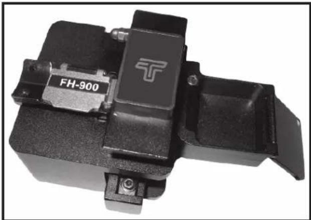
Close-up of a black mechanical component with a T-shaped logo and 'FH-900' label (no readable text beyond branding)Preface
Description
The Tempo Communications 915CL Optical Fiber Cleaver is intended to precisely cleavethefiberopticable for subsequent use in the 915FSFusion Splicer.
Safety
Safety is essential in the use and maintenance of Tempo tools and equipment. This instruction manual and an earmarkings on the tool provide information for avoiding hazards and unsafe practices related to the use of this tool. Observe all of the safety information provided.
Purpose of This Manual
This instruction manual is intended to familiarize all personnel with the safe operation and maintenance procedures for the Tempo Communications 915CL Optical Fiber Cleaver.
Keep this manual available to all personnel.
All specifications are nominal and may change as design improvements occur. Tempo Communications shall not be liable for damages resulting from misapplication or misuse of its products.
Important Safety Information
KEEP THIS MANUAL
| ⚠ WARNING | |
| Read and understand all of the instructions and safety information in this manual before operating or servicing this tool.Failure to observe this warning could result in severe injury or death. |
| ▲WARNUNG | |
| Electric shock hazard:Contact with live circuits could result in severe injury or death. |
| ⚠ WARNING | |
| Wear eye protection when using this tool.Fiberfragmentscanbeextremelydangerousiftheycomeinto contact with eyes or skin or are ingested. |
| ▲CAUTION |
| Collect all fiber scraps in the dust bin and dispose of them in an approved fiber disposal unit.Do not touch the cleaving wheel blade cutting area.Donotdisassembleorlubricate.ContactTempoformaintenanceand repairs.Store in a dry, clean location in the protective pouch.Failure to observe these precautions may result in injury and may damage the unit. |
Operation
- Open the fiber clamp mechanism and pull the fiber cleaving wheel mechanism back toward yourself.
- Place the fiber to be cleaved in the desired fiber adapter.

text_image
Load 900 micron fiber into the adapter so that the butter is flush with the end of the adapter.Hint: It is easier to load the fiber into the adapter if the fiber is curled in downward direction from the fiber clamp.
- Close the fiber clamp mechanism.
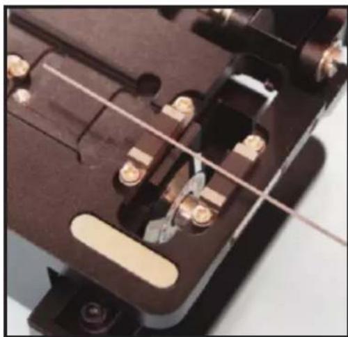
- Push the cleaving wheel mechanism away from yourself to cleavethe fiber.
Note: Dust bin is removed for these photos.
natural_image
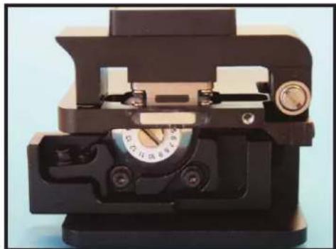
Close-up of a mechanical device with no visible text or symbolsCleaving Start Position

natural_image
Close-up of a mechanical device with no visible text or symbolsCleaving Finished Position
- Open the fiber clamp mechanism.
- Make sure that the cut fiber end is safely in the dust bin.
- Remove the adapter with the cleaved fiber from the cleaver.
- Place the adapter with the cleaved fiber into the 915FS for splicing.
Note: Thereisnoneedtoremovethecleavedfiberfromthefiberadapter after the cleaving operation.
Normal Use and Maintenance
Makesure that the rubber presser feet and the fiber guide groove are clean (no dust and fiber debris). Keep the fiber contact surfaces clean by using isopropyl alcohol with a lint free cleaning wand.
Changethepositionofthecleavingwheelifthecleavingqualitydegrades duetothebladebeingworn(usually1000cleavesperbladeposition).After thecleavingwheelhasbeenrotatedthroughall16positions,theheightcan be increased and the wheel can be reused through all of the 16 positions onceagain.Thecleavingwheelcanberotatedtwotimesforatotalof48,000 cleaves.
Blade Position Change
- Loosen blade locking screw.
- Rotate blade to next scale position.
- Hold side face of blade and lock screw at new position.

natural_image
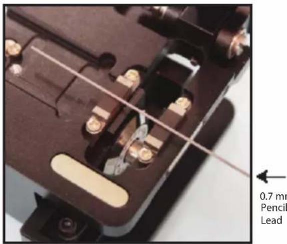
Close-up of a hand turning a rotary dial into a mechanical device (no visible text or symbols)- Lay 0.7 mm pencil lead across both pressure pads.
text_image
0.7 mm Pencil Lead- Move slider back and forth and check if blade touches pencil lead.
- Ifbladetouchespencillead: Performacleaveandcheckcleaveangle on 915FS.
If cleave is not good: Check if blade is damaged or dirty at new position.
- If blade drags pencil lead all the way across: Go to "Blade Height Adjustment".
- If blade does not touch pencil lead: Rotate pencil lead ≈ 180^ and try again.
If not sure: Perform a cleave and check cleave angle on 915FS.
If cleave is not good: Go to "Blade Height Adjustment".
Normal Use and Maintenance (con't)
Converting the 915CL to a Fixed Clamp Cleaver
Placethefixedclampmechanismintothe915CLandsecurewiththescrew provided.
The 900 micron and 250 micron fiber adapters can be permanently left in the 915FS fusions splicer. If desired one M2X5 screw scan be used to secure each fiber adapter from the fiber adapter mounting area of the 915FS.
natural_image
Close-up of a mechanical device with no visible text or symbolsFixed Clamp Mounting Screw
Blade Replacement
- Lay down cleaver with scale numbers on blade facing up.
- Remove blade locking screw.

natural_image
Close-up of a hand turning a rotary dial into a device (no visible text or symbols)- Remove old blade and replace with new blade. Donottouch blade (very sharp!) Use tweezers to remove old blade and insert new blade.

natural_image
Close-up of a hand holding a small electronic device with a metallic component and a label (no readable text or symbols)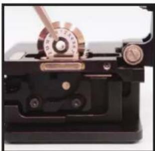
natural_image
Close-up of a mechanical device with copper and brass components (no visible text or symbols)- Lock new blade at position "1".

natural_image
Close-up of a hand turning a rotary knob with a metal dial (no visible text or symbols)- Lay 0.7 mm pencil lead across both pressure pads.
natural_image
Close-up of a mechanical component with metallic bolts and wiring (no visible text or symbols)
0.7 mm
Pencil
Lead
-
Move slider back and forth and check if blade touches pencil lead.
-
Ifbladetouchespencillead: Performacleaveandcheckcleaveangle on 915FS.
If cleave is not good: Check if blade is damaged or dirty at position "1". - If blade drags pencil lead all the way across: Go to "Blade Height Adjustment".
- If blade does not touch pencil lead: Rotate pencil lead ≈ 180^ and try again.
If not sure: Perform a cleave and check cleave angle on 915FS.
If cleave is not good: Go to "Blade Height Adjustment".
Normal Use and Maintenance (con't) Specifications
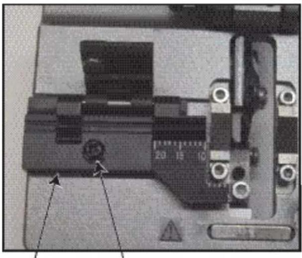
Blade Height Adjustment
- Loosen both compression screws and height locking screw.

text_image
① ② ③ ③1 - Height adjustment screw
2 - Height locking screw
3 - Compression screws for blade height adjustment arm
- Turn height adjustment screw:
• CW if blade did not touch pencil lead (moves blade up).
- CCW if blade dragged pencil lead across (moves blade down).
- Tighten height locking screw and both compression screws.
- Lay 0.7 mm pencil lead across both pressure pads.

natural_image
Close-up of a mechanical switch or relay component with metallic contacts and wiring (no visible text or symbols)
0.7 mm
Pencil
Lead
-
Move slider back and forth and check if blade touches pencil lead.
-
Ifbladetouchespencillead: Performacleaveandcheckcleaveangle on 915FS.
Ifcleave is not good: Checkifblade is damaged at current position. - If blade drags pencil lead all the way across: Go back to step 1 and adjust CCW until good.
- If blade does not touch pencil lead: Rotate pencil lead ≈ 180^ and try again.
If not sure: Perform a cleave and check cleave angle on 915FS.
If cleave is not good: Go back to step 1 and adjust CW until good.
| Fiber Type Single and multimode fiber |
| Fiber Size 0.25/0.9/3 mm (fiber holder replaceable) |
| Coating Diameter 125 μm |
| Cleaved Length 5mm - 20mm |
| Cleaved Angle Typically 0.5° |
| Blade Life 48,000 cleaves |
| Mode Semi-automatic |
| Dimensions(H×W×D)54 mm × 58 mm × 58 mm |
| Weight 310 g |
Troubleshooting
| Failure Mode Cause and Solution | |
| Fiberdoes not cleave.1 | Acrylic coating not removed from fiber.Fiber surface not clean.Clean rubber presser feet.Increase height of cleaving wheel. |
| End face has lip. | Increase height of cleaving wheel.Clean rubber feet.Check rubber feet for wear or abrasion. |
| End face has shadow or incline angle. | Increase height of cleaving wheel. |
| Core missing. | Lower height of cleaving wheel. |


Note: Contact Greenlee if the above chart does not provide a solution to attaining a reliable cleave.