
Elements E 115 SUB D - Speaker HK AUDIO - Free user manual and instructions
Find the device manual for free Elements E 115 SUB D HK AUDIO in PDF.
| Product Type | Active subwoofer for professional PA systems |
| Brand | HK Audio |
| Model | Elements E 115 SUB D |
| Dimensions (W x H x D) | 48.5 x 48.5 x 59.5 cm |
| Weight | 29.6 kg |
| Power Supply | 100-240 V~, 50-60 Hz (Powercon NAC3 In) |
| Amplifier Power (Sub) | 1500 W (Class D) |
| Amplifier Power (Mid/High) | 900 W (Class D) |
| Speaker | 1x 15" with 3" voice coil |
| Max SPL (10% THD) | 125 dB half space (40 Hz - X-Over) |
| Frequency Response (+/-3 dB) | 48 Hz - X-Over |
| Frequency Response (-10 dB) | 44 Hz - X-Over |
| Analog Inputs | 1x XLR combo balanced, 1x XLR Thru balanced |
| Speaker Outputs | 1x E-Connect, 1x Speakon (NL2), 1x XLR cardioid |
| Network Connection | Ethercon RJ45 In / Thru (Ethercon compatible) |
| Presets | 4 factory presets (1, 2, 3 E835) + 1 User Preset (Remote) |
| DSP Functions | 10-band parametric EQ, high/low pass filters, delay, limiter, mute (via DSP CONTROL software) |
| Special Features | Auto Sleep (standby after 4.5 h), Small Venue optimization, cardioid mode with L SUB 1500 A |
| Enclosure | MDF with black acrylic lacquer coating, 2 mm steel grille and acoustic foam |
| Mounting Points | 2x MultiGrip for suspension |
| Included Accessories | Powercon power cable, user manual, Locking Wedges |
| Maintenance | Clean only with a dry cloth. Do not open the enclosure. Repairs by qualified personnel only. |
| Safety | Do not expose to water or moisture. Use a grounded outlet. Follow mounting instructions. |
| Warranty | Online registration within 30 days of purchase at www.hkaudio.com |
| Manufacturer | Stamer Musikanlagen GmbH, Magdeburger Str. 8, 66606 St. Wendel, Germany |
Frequently Asked Questions - Elements E 115 SUB D HK AUDIO
User questions about Elements E 115 SUB D HK AUDIO
0 question about this device. Answer the ones you know or ask your own.
Ask a new question about this device
Download the instructions for your Speaker in PDF format for free! Find your manual Elements E 115 SUB D - HK AUDIO and take your electronic device back in hand. On this page are published all the documents necessary for the use of your device. Elements E 115 SUB D by HK AUDIO.
USER MANUAL Elements E 115 SUB D HK AUDIO
text_image
ELEMENTS E 115 Sub D MADE IN DEZEMARY Machining Seat C-63 Front Main Input Top Power Power Grid Power Grid Power Grid Power Grid Control Unit Control Unit Control Unit Control Unit Control Unit Control Unit Control Unit Control Unit Control Unit Control Unit Control Unit Control Unit Control Unit Control Unit Control Unit Control Unit Control Unit Control Unit Control Unit Control Unit Control Unit Control Unit Control Unit Control Unit Control Unit Control Unit Control Unit Control Unit Control Unit Control Unit Control Unit Control Unit Control Unit Control UnitELEMENTS
E 115 Sub D
MANUAL 1.0
Important Safety Instructions! Read before connecting!
This product has been built by the manufacturer in accordance with IEC 62368-1 and left the factory in safe working order. To maintain this condition and ensure non-risk operation, the user must follow the advice and warning comments found in the operating instructions. If this product shall be used in vehicles, ships or aircraft or at altitudes exceeding 2000 m above sea level, take care of the relevant safety regulations which may exceed the IEC 62368-1 requirements.
WARNING: To prevent the risk of fire and shock hazard, do not expose this appliance to moisture or rain. Do not open case – no user serviceable parts inside. Refer service to qualified service personnel.

This symbol, wherever it appears, alerts you to the presence of regulated dangerous voltage inside the enclosure – voltage that sufficient to constitute a risk of shock.

This symbol, wherever it appears, alerts you to the presence normally accessible hazardous voltage. External wiring connected terminal marked with this symbol must be a "ready made complying with the manufacturers recommendations, or must being installed by instructed persons only.

This symbol, wherever it appears, alerts you to important and maintenance instructions in the accompanying e. Read the manual.

This symbol, wherever it appears, tells you: Take care! Hot To prevent burns you must not touch.

All electrical and electronic products including batteries
should be disposed of separately from the municipal waste stream via designated collection facilities appointed by the government or the local authorities.

Read these instructions. Keep these instructions. Follow all gs and instructions marked on the product and in this manual.
- Do not use this product near water. Do not place the product near water, baths, wash basins, kitchen sinks, wet areas, swimming pools or damp rooms.
- Do not place objects containing liquid on the product – vases, glasses, bottles etc.
- Clean only with dry cloth.
- Do not remove any covers or sections of the housing.
- The set operating voltage of the product must match the local mains supply voltage. If you are not sure of the type of power available consult your dealer or local power company.
- Before connecting the device, please ensure that the mains supply you are using is equipped with adequate protection against short circuiting and grounding faults when the device is plugged in.
- To reduce the risk of electrical shock, the grounding of this product must be maintained. Use only the power supply cord provided with this product, and maintain the function of the center (grounding) pin of the mains connection at any time. Make sure the mains outlet used provides a proper protective ground connection.
- Do not defeat the safety purpose of the polarized or grounding-type plug. A polarized plug has two blades with one wider than the other. A grounding type plug has two blades and a third grounding prong. The wide blade or the third prong are provided for your safety. If the provided plug does not fit into your outlet, consult an electrician for replacement of the obsolete outlet.
- Protect the power cord from being walked on or pinched particularly at plugs, convenience receptacles, and the point where they exit from the device! Power supply cords should always be handled carefully. Periodically check cords for cuts or sign of stress, especially at the plug and the point where the cord exits the device.
- Never use a damaged power cord.
- Unplug this product during lightning storms or when unused for long periods of time.
-
This product can be fully disconnected from mains only by pulling the mains plug at the unit or the wall socket. The product must be placed in such a way at any time, that disconnecting from mains is easily possible.
-
Fuses are to be replaced exclusively by qualified personnel, and then only with fuses of the proper type and rating.
- Refer all servicing to qualified service personnel. Servicing is required when the unit has been damaged in any way, such as:
- When the power cord or plug is damaged or frayed.
- If liquid has been spilled or objects have fallen into the product.
- If the product has been exposed to rain or moisture.
- If the product does not operate normally when the operating instructions are followed.
- If the product has been dropped or the cabinet has been damaged.
- Do not connect external speakers to this product with an impedance lower than the rated impedance given on the product or in this manual. Use only cables with sufficient cross section according to the local safety regulations.
- Keep away from direct sunlight.
- Do not install near heat sources such as radiators, heat registers, stoves or other devices that produce heat.
- This apparatus is for moderate climates areas use, not suitable for use in tropical climates countries.
- Do not block any ventilation openings. Install in accordance with manufacturer's instructions. This product must not be placed in a built-in installation such as a rack unless proper ventilation is provided.
- Always allow a cold device to warm up to ambient temperature, when being moved into a room. Condensation can form inside it and damage the product, when being used without warming up.
- Do not place naked flame sources, such as lighted candles on the product.
- The device must be positioned at least 20 cm/8" away from walls.
- Use only with the cart, stand, tripod, bracket or table specified by the manufacturer or sold with the product. When a cart is used, use caution when moving the cart/product combination to avoid injury from tip-over.
- Use only accessories recommended by the manufacturer, this applies for all kind of accessories, for example protective covers, transport bags, stands, wall or ceiling mounting equipment. In case of attaching any kind of accessories to the product, always follow the instructions for use, provided by the manufacturer. Never use fixing points on the product other than specified by the manufacturer.
- This appliance is NOT suitable to be used by any person or persons (including children) with limited physical, sensorical or mental ability, or by persons with insufficient experience and/or knowledge to operate such an appliance. Children under 4 years of age must be kept away from this appliance at all times.
- Never push objects of any kind into this product through cabinet slots as they may touch dangerous voltage points or short out parts that could result in risk of fire or electric shock.
- This product is capable of delivering sound pressure levels in excess of 90 dB, which may cause permanent hearing damage! Exposure to extremely high noise levels may cause a permanent hearing loss. Wear hearing protection if continuously exposed to such high levels.
- The manufacturer only guarantees the safety, reliability and efficiency of this product if:
- Assembly, extension, re-adjustment, modifications or repairs are carried out by the manufacturer or by persons authorized to do so.
- The electrical installation of the relevant area complies with the requirements of IEC (ANSI) specifications.
- The unit is used in accordance with the operating instructions.
- This product is optimized for use with music and speech signals. Using this product with sine wave, square wave or other kind of measuring signals at higher level may lead to severe damage of the product.
General Notes on Safety for Loudspeaker Systems

Mounting systems may only be used for those loudspeaker systems authorized by the manufacturer and only with the mounting accessories specified by the manufacturer in the installation instructions. Read and heed the manufacturer's installation instructions. The indicated load-bearing capacity cannot be guaranteed and the manufacturer will not be liable for damages in the event of improper installation or the use of unauthorized mounting accessories.
The system's load-bearing capacity cannot be guaranteed and the manufacturer will not be liable for damages in the event that loudspeakers, mounting accessories, and connecting and attaching components are modified in any way.
Components affecting safety may only be repaired by the
manufacturer or authorized agents, otherwise the operating permit will be voided.

Installation may be performed qualified personnel only, then only at pick-points with sufficient load-carrying capacity compliance with local building regulations. Use only the using hardware specified by the manufacturer in the installation actions (screws, anchors, etc.). Take all the precautions necessary to be bolted connections and other threaded locking devices will open.

Fixed and portable installations (in this case, speakers mounting accessories) must be secured by two independent risks to prevent them from falling. Safeties must be able to accessories or parts that are loose or may become loose. Compliance with the given national regulations when using ringing, attaching, and rigging devices. Factor potential dynamic (jerk) into the equation when determining the proper size and bearing capacity of safeties.

Be sure to observe speaker stands' maximum load-bearing activity. Note that for reasons of design and construction, most other stands are approved to bear centric loads only; that is, the others' mass has to be precisely centered and balanced. Ensure other stands are set up stably and securely. Take appropriate added reserves to secure speaker stands, for example when:
- the floor or ground surface does not provide a stable, secure base.
- they are extended to heights that impede stability.
- high wind pressure may be expected.
- there is the risk that they may be knocked over by people.
Special measures may become necessary as precautions against unsafe audience behavior. Do not set up speaker stands in evacuation routes and emergency exits. Ensure corridors are wide enough and put proper barriers and markings in place when setting speaker stands up in passageways. Mounting and dismounting are especially hazardous tasks. Use aids suitable for this purpose. Observe the given national regulations when doing so.


Wear proper protection (in particular, a helmet,
gloves, and safety shoes) and use only suitable means of ascent (ladders, scaffolds, etc.) during installation. Compliance with this requirement is the sole responsibility of the company performing the installation.

WARNING! After installation, inspect the system comprised mounting fixtures and loudspeakers to ensure it is properly d.
The operator of loudspeaker systems (fixed or portable) must regularly inspect or task a third party to regularly inspect all system components in accordance with the given country's regulations and have possible defects repaired immediately.
We also strongly recommend maintaining a logbook or the like to document all inspections.
Also be sure to provide sufficient safety margins for the rigging points used for flown systems. Observe the given national regulations when doing so.

Professional loudspeaker systems can produce harmful
volume levels. Even prolonged exposure to seemingly harmless levels (starting at about 95 dBA SPL) can cause permanent hearing damage! Therefore we recommend that everyone who is exposed to high volume levels produced by loudspeaker systems wears professional hearing protection (earplugs or earmuffs).
Manufacturer: Stamer Musikanlagen GmbH, Magdeburger Str. 8, 66606 St. Wendel, Germany
ELEMENTS E 115 Sub D
Welcome to the HK Audio family!
Thank you for choosing a brand-name product made by our company. Rest assured, we engineered and built it with the greatest care so it will serve you well for many tomorrows to come.

Even if your experience with sound systems runs deep, some things about this product are sure to be new to you. This is why we ask that you do not set this manual aside without reading it first. Be sure to keep it in a safe place for later reference.
Here's wishing you the best sound at every occasion!
Your HK Audio team
Warranty
Use the convenient online registration option at www.hkaudio.com.

http://warranty.hkaudio.com
The registration is only valid if the device is registered within 30 days of the date of purchase.
HK AUDIO
Technischer Service
Postfach 1509
66595 St. Wendel, Germany
Fax: +49 6851 905 100

Powerful electromagnetic interference and electrostatic discharges may impair this unit's operation. In the event of such interference, switch the device off and back on again. If this fails to restore the normal mode of operation, please move the unit away from the source of interference and try again.
1 General Information
Unpacking and Inventorying
When you first unpack your ELEMENTS E 115 SUB D speaker cabinet, take a quick inventory to make sure it comes complete with the manual and Powercon mains cable.
The System's Components
Heads up: Please be advised that the E 115 SUB D subwoofer may only be operated in combination with passive HK Audio ELEMENTS components. Heads up: Connecting any component other than ELEMENTS mid/high units to this Speakon output may damage it and destroy the subwoofer's electronics.
Powering Up
Make certain that the E 115 SUB D is switched off when you set up the system, otherwise you risk damaging it! Always set up the entire system and connect all cables first, and then switch on the subwoofer last. When tearing the system down, always switch off the ELEMENTS subwoofer first.
text_image
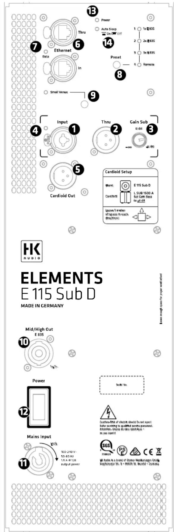
ELEMENTS E 115 Sub D MADE IN GERMANY Mid/High Out E 835 Power Mains Input 10 14 6 7 Data Ethernet In Preset Small Venue 9 13 Power Auto Sleep On Off Off 1 1x @835 2 2x @835 3 3x @835 4 Remote 8 14 1 2 3 4 5 6 7 8 9 10 11 12 13 14 15 16 17 18 19 20 21 22 23 24 25 26 27 28 29 30 31 32 33 34 35 36 37 38 39 40 41 42 43 44 45 46 47 48 49 50 51 52 53 54 55 56 57 58 59 60 61 62 63 64 65 66 67 68 69 70 71 72 73 74 75 76 77 78 79 80 81 82 83 84 85 86 87 88 89 902 Connectors and Controls
① Input
This XLR/1/4" (6.35 mm) combo jack provides a balanced input for analog signals.
2 Thru
Use this parallel, balanced XLR output to send the signal routed into the Input through to other components. This output remains active even when the electronic components are deactivated.
3 Gain Sub
Use this knob to adjust the input gain for the incoming signal. Heads up: This knob adjusts the volume of the E 115 SUB D. It does not address or affect the connected mid/high units. We recommend starting with it set to 0 dB at the center or 12 o'clock position.
4 Input/Limiter LED
This LED lights up green to indicate incoming signals and red to indicate signal peaks. The LED briefly flashes red to tell you the Limiter is responding to signal peaks. If it stays red, turn down the Gain knob.
5 Cardioid Out
Connect a matching HK Audio L SUB 1500 A subwoofer to this output when configuring cardioid setups. See section 5.2 for more on this.
6 Ethernet In /Thru
Use the two Ethercon ports to integrate the speaker into a network. They accept RJ45 and Ethercon (NE8 MX, NE8 MX6, NE8 MC) plugs. Use the Ethernet Thru port to forward the network signal.
Always use S/STP or S/FTP cables to shield against electromagnetic interference. We recommend CAT6 cables. A separate manual explains the finer points of network integration, remote control functions and audio streaming*.
You will find it on the ELEMENTS D download page at www.hkaudio.com. For a brief description of the DSP functions, see section 8 Preset.
7 Data
This LED lights up orange when data flows through the network connector.
8 Preset
Use the Preset selection button to call up factory presets or a user preset you can configure via the remote DSP CONTROL software. Tap the select button once to scroll through Presets 1 through 4.
A separate manual explains how to program the four remote user presets. You will find it on the ELEMENTS D download page at www.hkaudio.com.
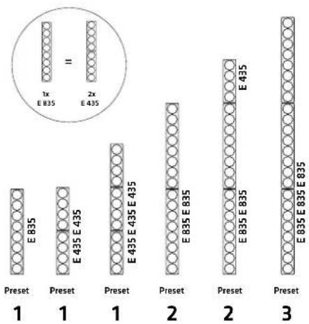
Heads up: Selecting the proper preset tunes the subwoofer's frequency response to match the frequency response of the connected mid/high units. It is essential that you to do this manually because the power amp cannot automatically detect the number of connected mid/high units. Heads up: The numbers indicated for the Filter button always apply to the E 835 model of mid/high unit. Be sure to multiply that number by two when using the E 435 model.
Preset 1: 1x E 835 (2x E 435)
Preset 2: 2x E 835 (4x E 435)
Preset 3: 3x E 835 (6x E 435)
Heads up: You can combine the two models in a mixed configuration, for example, two E 835s and two E 435s. It this case, you would select Preset 3. You can even connect an odd number of E 435s, say, two E 835s and one E 435s or three E 435s. In these cases, select the next lower preset number and, if necessary, adjust the high frequencies using the mixer's EQ or the frequency response using HK Audio DSP CONTROL software.
bar
| Category | Preset 1 | Preset 2 | Preset 3 | | :--- | :--- | :--- | :--- | | Group 1 (E835) | 1x E835 | 2x E435 | 1x E835 | | Group 2 (E835 E835) | 1x E835 | 2x E435 | 1x E835 | | Group 3 (E835 E835 E835) | 1x E835 | 2x E435 | 1x E835 |Preset 4: Remote
This setting loads a user preset previously saved via the DSP CONTROL application. The subwoofer does not need to be connected to the remote software to do this.
You can save the following DSP functions via the remote DSP CONTROL software as user presets – the fully parametric ten-band EQ with variable filter characteristics for each frequency band, a high-pass and a low-pass filter with variable filter characteristics, and limiter, delay, level and mute.
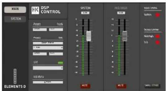
text_image
MAIN SYSTEM HK DSP CONTROL Parameters Length 0.000 1.000 2.000 3.000 4.000 5.000 6.000 7.000 8.000 9.000 10.000 SYSTEM 2.00 MINI MINI MAX/THICK SoMain Standard Unit Maxing Side CHANNEL OUTPUTThis screenshot shows the remote DSP CONTROL software. You can get this free application from the ELEMENTS D product download page at www.hkaudio.com.
9 Small Venue
We tuned your ELEMENTS system's frequency response for larger rooms, which require speakers to throw sound over greater distances. When setting the system up in smaller rooms, activate the Small Venue EQ with this switch so the red LED lights up. This re-voices the system for it to sound balanced and remarkably transparent even at very short range.
10 Mid/High Out
Connect ELEMENTS mid/high units to this Speakon output via the EF 45 base (available as an accessory) or to forward their signal to an ELEMENTS Install Kit.
Use standard cables equipped with Speakon NL2 connectors to this end. Plug in the Speakon cable and turn the connector clockwise to lock it in place. Be sure to first turn the connector counterclockwise to unlock it before unplugging it.
Heads up: Mid/High Out is wired in parallel to the E-Connect (15) signal bus on top of the E 115 SUB D. Use this output only when the E-Connect bus is not in use.
Heads up: Connecting any component other than ELEMENTS mid/high units to this Speakon output may damage it and destroy the subwoofer's electronics.
11 Mains Input
Use the factory-included Powercon mains cord to connect this socket to a power outlet. Insert the push-pull connector and turn it clockwise to make sure the Powercon cord engages and locks. To unlock it, pull the Powercon plug's locking mechanism towards the cable and turn it counterclockwise.
12 Power
This rocker switch turns the power on and off. Set it to Power to turn the electronic components on and to Off to disconnect them from the mains power supply.
13 Power-LED
This LED lights up green when the electronic components are getting mains power.
14 Auto Sleep
Use this recessed button to switch energy-saving Auto Sleep mode on and off. Your speaker leaves the factory with the Auto Sleep button pressed to enable this mode. This function puts the electronic components to sleep when four and a half hours pass without the speaker registering an audio signal, data sent to the Ethercon ports, or an adjustment of a button or knob. The only way to wake it up is by switching the Power button off and on again or patching an analog audio signal into the Input.
15 E-Connect
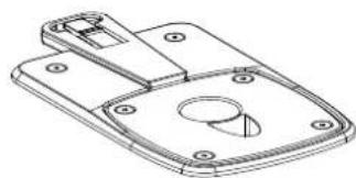
natural_image
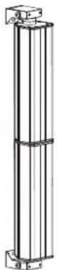
Technical line drawing of a mechanical component with mounting holes and a circular feature (no text or symbols)The dual-purpose ELEMENTS E-Connect output/coupler is located on the top of the E 115 SUB D enclosure. Use it to connect E 835 and E 435 mid/high units and the EP 1 and EP 2 speaker extension poles. The subwoofer can drive up to three E 835 mid/high units or up to six E 435s. For more on this, see section 3, Setting Up and Connecting the Column's components. Heads up: The E-Connect bus is wired in parallel to the Mid/High Output on the rear panel (Speakon). Use it only when the Speakon Out port is not in use.
3 Setting Up and Connecting the Column's Components
3.1 E-Connect
E-Connect is a fast, reliable and cordless way of linking the ELEMENTS' passive components. This dual-purpose coupler provides physical and audio links that connect the E 835 mid/high-units, the EP1 / EP 2 speaker extension pole and the EF 45 base.
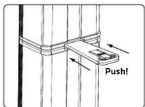
3.2 Connecting the Column's Components
Line up the two components so that the pole end faces the sleeve. Insert the pole end all the way into sleeve until the detent button snaps into place, making sure you have a solid connection.
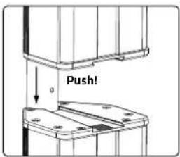
text_image
Push!To disconnect and separate the units, press and hold the button on the E-Connector to release the detent and then pull the two components apart.
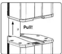
text_image
Pull!Heads up: Always set the system up on flat, level and firm surfaces.
4 Setting Up
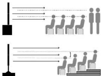
4.1 Vertical Alignment
What height is right?
Line array systems like ELEMENTS deliver a fairly narrow vertical output pattern. This is why you want to aim the speakers so the center of the column is roughly in line with the audience's heads.
flowchart
graph TD
    A["Person"] --> B["Group 1"]
    A --> C["Group 2"]
    D["Person"] --> E["Group 1"]
    D --> F["Group 2"]
    G["Person"] --> H["Group 1"]
    G --> I["Group 2"]
    J["Person"] --> K["Group 1"]
    J --> L["Group 2"]
    M["Person"] --> N["Group 1"]
    M --> O["Group 2"]
    P["Person"] --> Q["Group 1"]
    P --> R["Group 2"]
    S["Person"] --> T["Group 1"]
    S --> U["Group 2"]
    V["Person"] --> W["Group 1"]
    V --> X["Group 2"]
    Y["Person"] --> Z["Group 1"]
    Y --> AA["Group 2"]
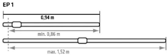
Two speaker extension poles of different lengths, the EP 1 and the EP 2, are available to adjust the column's height.
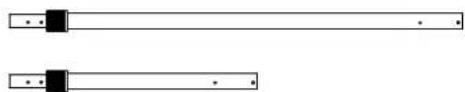
natural_image
Two horizontal rectangular bars with black connectors and dots, no text or symbols presentEquipped with the cordless E-Connect bus/coupler, they provide a fast, easy way of setting up smaller configurations and connecting mid/high units. Consult the technical specifications to learn the exact measurements of the two speaker extension poles.
Heads up: Never connect two speaker extension poles to each other!
4.2 Horizontal Alignment
A mid/high column's horizontal directivity is around 70^ . Depending on the application, you may want to turn the columns inwards towards the audience area to direct the system's power where it is needed most.
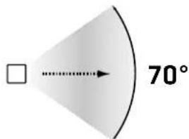
text_image
70°You'll get the best sound and coverage when all connected components project at the same angle. The included locking wedges lets you lock down the ELEMENTS mid/high-units so their aim remains true and they can't drift to the left or right.
text_image
Push!Insert the locking wedge into the slot until it clicks into place. Apply slight pressure to the center panel to release and remove it.
4.3 Maximum Conf i guration
This is the largest system you can configure with the E 115 SUB D:
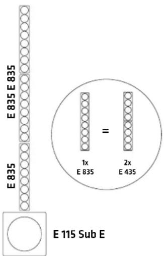
text_image
E835 E835 E835 = 1x E 835 2x E 435 E 115 Sub E5 Bass Extension and Cardioid Setups with the HK Audio L SUB 1500 A
A perfect acoustical, mechanical and visual match, the powered HK Audio L SUB 1500 A subwoofer is the ideal complement to the E 115 SUB D. Be sure to set the L SUB 1500 A's Phase switch to 0 degrees and the X-Over Bass switch to 100 Hz before connecting this subwoofer. The position of the Confi guration switch is irrelevant in this case because it only aff ects the level of the L SUB 1500 A's Line Out Mid/High ports.
The E 115 SUB D offers two outputs that let you add on the L SUB 1500 A, either as a bass extension or to configure a cardioid setup:
5.1 Operating the L SUB 1500 A as a Bass Extension
Connect the L SUB 1500 A to the Thru ports on the E 115 SUB A for it to receive the unprocessed signal routed into the E 115 SUB D's input. Adjust the level using the Gain Bass knob on the L SUB 1500 A. In this case, you can place the L SUB 1500 A beneath or beside the E 115 SUB D.
text_image
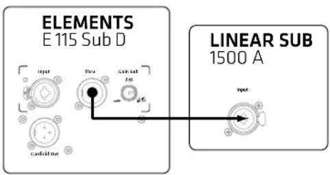
ELEMENTS E 115 Sub D Input True Gain Sub End φK LINEAR SUB 1500 A Input5.2 Operating the L SUB 1500 A in a Cardioid Setup
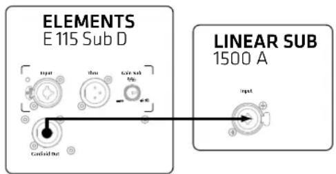
The E 115 SUB D is equipped with a separate Cardioid Out bus. Providing a signal tuned precisely to the L SUB 1500 A, this output lets you confi gure a cardioid setup with a rearward-facing L SUB 1500 A without having to make any other adjustments. However, please be sure to set the Gain Bass knob on the L SUB 1500 A to +6 dB by turning it clockwise to the far right position, the Phase switch to 0 degrees, and the X-Over switch to 100 Hz. The E 115 SUB D's DSP will take care of the rest.
text_image
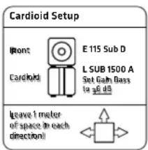
ELEMENTS E 115 Sub D LINEAR SUB 1500 AHeads up: The cardioid setup requires the L SUB 1500 A to be placed below the E 115 SUB D. A side-by-side array will not achieve the desired effect! Also, be sure to always maintain a distance of at least one meter from walls.
text_image
Cardioid Setup Front Cardioid E 115 Sub D L SUB 1500 A Set Gain Bass to dB dB Leave 1 meter of space in each direction!When is it a good idea to go with a cardioid setup?
While speakers are able to throw midrange and high frequencies in directional patterns, low frequencies tend to radiate in all directions. Excessive bass levels can often be a problem on and behind the stage. And promoters are increasingly making demands to limit sound systems' low-end reach, for example, in festival tents at urban venues. Such demands for limiting low-range frequencies' range are best met with cardioid setups. With its hardware appointments and filter sets, the E 115 SUB D provides a fast, easy way to configure effective cardioid setups.
6 Deploying Mid/High Units in Distributed Setups
You can use the EF 45 base or the wall-mount Install Kit to set up mid/high units elsewhere rather than stacking them on the subwoofer.
Heads up: HK Audio DSP Control software lets you adjust separately the delay times for the signals sent to the mid/high units and the subwoofer. This way, you can place or mount the mid/high units in front of or behind the subwoofer. Say you want to place the mid/high units two meters behind the subwoofer because of space constraints: To do this, you would have to delay the signal sent to the subwoofer by the time it takes to travel those two meters. Once you set this delay time, you can store it as a preset on the subwoofer, so the software does not have to be running and connected to the subwoofer for this configuration to work.
6.1 EF 45
natural_image
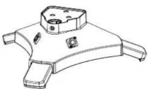
Technical line drawing of a mechanical component with mounting holes and a central hub (no text or symbols)The EF 45 base provides the pedestal for the mid/high units and the speaker extension poles. Its retractable and extendible feet serve as a stable, secure platform.
When setting up an ELEMENTS system with the EF 45 base, make sure the feet are fully extended and locked in placed with the set-screws.
The base has an E-Connect coupler on top and two parallel Speakon connectors on the rear. Connect mid/high units and speaker extension poles to the E-Connect, and one of the two Speakon connectors to the Speakon Mid/High Out on the E 115 SUB D.
Heads up: The EF 45 has two Speakon connectors to allow the signal to be routed through when you have several mid/high units mounted side by side on the EF 45/EP1 or mounted with the Install Kit, for example, to cover very wide rooms. In this case, make sure the preset selected on the subwoofer corresponds to the number of mid/high units mounted on each stand or Install Kit rather than the total number of connected mid/high units.
Heads up: The maximum number of mid/high units still applies in this case. Do not connect more than three E 835s or six E 435s to the subwoofer!
6.2 E 435 INSTALL KIT
The ELEMENTS INSTALL KIT consists of two modified E 435 mid/high units with a mounting bracket. It can be extended with up to two E 835s or four E 435s. Installation instructions are included with the Install Kit and may be downloaded from www.hkaudio.com.
7 Optional HK Audio Accessories
1. REAR PROTECTION PLATE
(for the E 115 SUB D and L SUB 1500 A)
Made of sturdy yet light aluminum, this rear-panel cover splash-proofs the L SUB 1500 A's electronic components and guards against unauthorized handling in cardioid mode.
2. ELEMENTS BASE BAG
Padded soft case for one EF 45 base
3. ELEMENTS SOFT BAG
Padded soft case for two E 835 units
4. ROLLER BAG E 115 SUB D
Content: One padded soft case for the subwoofer with an integrated dolly board
The padded roller bag has a sturdy dolly board built in. You can also attach two bags containing two E 835s / four E 435s and a speaker extension pole on top to easily transport and quickly assemble an entire system.
5. E 115 SUB D COVER
A padded cover is available as an alternative to the roller bag. It also fits the L SUB 1500 A add-on bass bin.
6. 100 mm BLUE SWIVEL CASTERS
The optional swivel castors are mounted to the rear of the E 115 SUB D subwoofer using the self-locking screws at the corners.
Heads up: The subwoofer does not fit in the ROLLER BAG with the swivel casters mounted. However, it will fit in the soft cover.
8 Technical Specifications
| E 115 SUB D | |
| Max. SPL @ 10% THD 125 dB | half space (40 Hz - X-Over averaged) |
| Max. SPL peak @ 10% THD 125 dB | 28 dB half space @90 Hz |
| Frequency response +/- 3 dB | 48 Hz - X-Over |
| Frequency response -10 dB | 44 Hz - X-Over |
| Power output, Sub 1500 W | |
| Power output, Mid/High Units | 900 W |
| Amp type Class D | |
| Bass woofer 1x 15", 3" voice coil | |
| Active x-over frequency 160 Hz | |
| Analog ports 1x XLR Combo n bal.,1x XLR Thru bal. | |
| Speaker Outs 1x E-Connect, 1x Speakon | |
| Cardioid Out 1x XLR | |
| Network port Ethercon RJ45 | 1x In, 1x Thru |
| Filter presets 1x E 835, 2x E 835, 3x E 835, Remote | |
| Remote software DSP CONT | ROL (Windows, Mac OS) |
| DSP functions | Fully parametric 10-band EQ with variable filter characteristics, High-Pass Filter, Low-Pass Filter, Polarity, Level, Delay, Limiter, Mute |
| Sampling rate | 96 kHz |
| System latency | less than 2.6 ms |
| Mains connector | 1x Powercon NAC3 In, 100-240 V |
| Power consumption | 1 A / 100-240 V nominal according to EN 62368-1 |
| Grips | 2x MultiGrip |
| Housing | MDF |
| Finish | Black acrylic enamel |
| Front grille | 2 mm metal grille backed with black acoustic foam |
| Dimensions (WxHxD) | 48.5 x 48.5 x 59.5 cm |
| Weight | 29,6 kg / 65.3 lbs |
| E 835 Mid/High Unit | |
| Power handling,nominal(RMS) | 300 W @ 8 ohms |
| Axial sensitivity 1W/1m | 100 dB Halfspace |
| Frequency response -10 dB | 140 Hz - 20 kHz |
| Speakers | 8 x 3.5" broadband |
| Directivity | 70° horizontal |
| Corner frequency | 140 Hz, 30 dB/oct. |
| Connectors | 1x E-Connect In, 1x E-Connect Out |
| Dimensions (WxHxD) | 11 x 74.5 x 12 cm (excl. E-Connect sleeves) |
| Weight | 4.5 kg / 9.9 lbs |
text_image
EP 1 0,94 m mln. 0,86 m max. 1,52 m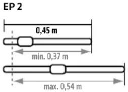
text_image
EP 2 0,45 m min. 0,37 m max. 0,54 m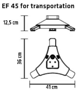
text_image
EF 45 for transportation 12,5 cm 36 cm 41 cm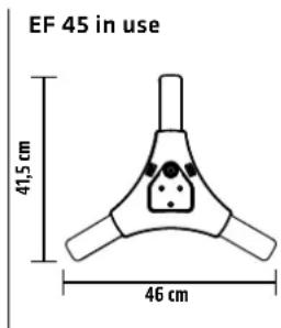
text_image
EF 45 in use 41,5 cm 46 cmtext_image
ELEMENTS E 115 Sub D MADE IN GERMANY Mid/High Out E 835 Power Mains Input 10 12 9 8 7 6 5 4 3 2 1 13 Power Auto Sleep On Off Off 1 1x @835 2 2x @835 3 3x @835 4 Remote Ethernet Data In Preset Small Venue 9 Gain Sub to dali -∞ 4x ddi Cardioid Setup Plant: E 115 Sub D Cardioid: L SUB 1500 A Set Gain Bass to 4x ddi Leave Diameter off space in each direction) Leave enough space for proper ventilation Sweitz No. Cantina Risk of electric shock Do not open. Rohor switching to qualified surface personnel. Attitudes. Requis de chee Stuck/Regn - we pay out until! SRS PS CE Werk Rakes is a brand of Stamer Waspianages Grisalay Waspianages St. & 96606 St. (Ward) - Germanynatural_image
Technical line drawing of a mechanical bracket or mounting plate with mounting holes and a circular cutout (no text or symbols)flowchart
graph TD
    A["Top: Seat with 3 people"] --> B["Left: Column with 1 person"]
    B --> C["Right: Column with 2 people"]
    C --> D["Bottom: Column with 1 person"]
    D --> E["Left: Column with 1 person"]
    style A fill:#f9f,stroke:#333
    style E fill:#bbf,stroke:#333
natural_image
Two horizontal cylindrical objects with black connectors and dots, no text or symbols presenttext_image
Cardioid Setup Front Cardioid E 115 Sub D L SUB 1500 A Set Gain Bass to 5 dB Leave 1 meter of space in each direction!natural_image
Technical line drawing of a mechanical component with four legs and mounting holes (no text or symbols)natural_image
Technical line drawing of a mechanical component with mounting holes and a central circular feature (no text or symbols)natural_image
Two horizontal cylindrical objects with black connectors and small dots, no text or symbols presenttext_image
Cardioid Setup Front Cardboard E 115 Sub D L SUB 1500 A Set Gain Bass to 6 dB Leave 1 meter of space to each direction!natural_image
Technical line drawing of a mechanical component with four legs and mounting holes (no text or symbols)text_image
ELEMENTS E 115 Sub D MADE IN GERMANY Mid/High Out E 835 Power Mains Input 10 12 9 8 7 6 5 4 3 2 1 13 Power Auto Sleep On Off Off 1 1x @835 2 2x @835 3 3x @835 4 Remote Ethernet Data In Preset Small Venue 9 Gain Sub to dali -∞ 4x ddi Cardioid Setup Plant: E 115 Sub D Cardioid: L SUB 1500 A Set Gain Bass to 4x ddi Leave filter off space in each direction) Leave enough space for proper ventilation Sweitz No. Cantina Risk of electric shock Do not open. Rohor switching to qualified surface personnel. Attitudes. Requis de chee Stuck/Regn - we pay out until! SRS PS CE Werk Rakes is a brand of Stamer Waspianages Grisalay Waspianages St. & 96606 St. (Ward) - Germanynatural_image
Technical line drawing of a mechanical bracket or mounting plate with mounting holes and a circular cutout (no text or symbols)natural_image
Two horizontal cylindrical objects with black connectors and dots, no text or symbols presenttext_image
ELEMENTS E 115 Sub D LINEAR SUB 1500 A input this can out for 4% Circuit bus inputtext_image
Cardioid Setup Front Cardioid E 115 Sub D L SUB 1500 A Set Gain Bass to 5 dB Leave 1 meter of space in each direction!!natural_image
Technical line drawing of a mechanical component with four legs and mounting holes (no text or symbols)(per E 115 SUB De L SUB 1500 A)