
Vortis 2 VR2-11210 - Loudspeaker HK AUDIO - Free user manual and instructions
Find the device manual for free Vortis 2 VR2-11210 HK AUDIO in PDF.

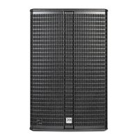
| Product Type | Passive two-way loudspeaker |
| Model | Vortis 2 VR2-11210 |
| Mounting Accessories | U-bracket, speaker tilt, wall plate, cluster plates, TB-R tilt bracket, AP-10 B attachment point |
| Cluster Capability | Vertical and horizontal clustering with 0° and 10° cluster plates; up to 3 enclosures |
| Horn Adjustment | Rotatable 90° for coverage pattern adjustment |
| Ball Impact Protection | Pre-installed safety plate (metal strip) per DIN 18032-3 |
| Maximum Load Capacity (U-bracket) | 2 speakers (1-point suspension), 3 speakers (2-point suspension) |
| Safety Features | Two independent safeties required; secondary safety/arrest wire recommend; M10 rigging points |
| Installation Compliance | Must be installed by qualified personnel; comply with local building regulations |
| Intended Use | Professional sound reinforcement, fixed or portable installations |
Frequently Asked Questions - Vortis 2 VR2-11210 HK AUDIO
User questions about Vortis 2 VR2-11210 HK AUDIO
0 question about this device. Answer the ones you know or ask your own.
Ask a new question about this device
Download the instructions for your Loudspeaker in PDF format for free! Find your manual Vortis 2 VR2-11210 - HK AUDIO and take your electronic device back in hand. On this page are published all the documents necessary for the use of your device. Vortis 2 VR2-11210 by HK AUDIO.
USER MANUAL Vortis 2 VR2-11210 HK AUDIO
Mounting Accessories
- Manual 1.1
General Notes on Safety for Loudspeaker Systems

Mounting systems may only be used for those loudspeaker systems authorized by the manufacturer and only with the mounting accessories specified by the manufacturer in the Installation Instructions. Read and heed the manufacturer's Installation Instructions. The indicated lead bearing capacity cannot be guaranteed and the manufacturer will not be liable for damages in the event of Improper Installation or the use of unauthorized mounting accessories.
The system's load-bearing capacity cannot be guaranteed and the manufacturer will not be liable for damages in the event that loudspeakers, mounting accessories, and connecting and attaching components are modified in any way.
Components affecting safety may only be repaired by the manufacturer or authorized agents, otherwise the operating permit will be voided.

Installation may be performed by qualified personnel only, and then only at pick-points with sufficient load-carrying capacity and in compliance with local building regulations. Use only the mounting hardware specified by the manufacturer in the installation instructions (screws, anchors, etc.). Take all the precautions necessary to ensure bolted connections and other threaded locking devices will not loosen.

Fixed and portable installations (in this case, speakers and mounting accessories) must be secured by two independent safeties to prevent them from falling. Safeties must be able to catch accessories or parts that are loose or may become loose. Ensure compliance with the given national regulations when using connecting, attaching, and rigging devices. Factor potential dynamic forces (jerk) into the equation when determining the proper size and load-bearing capacity of safeties.

Be sure to observe speaker stands' maximum load-bearing capacity. Note that for reasons of design and construction, most speaker stands are approved to bear centric loads only; that is, the speakers' mass has to be precisely centered and balanced. Ensure speaker stands are set up stably and securely. Take appropriate added measures to secure speaker stands, for example when:
- the floor or ground surface does not provide a stable, secure base.
- they are extended to heights that impede stability.
- high wind pressure may be expected.
- there is the risk that they may be knocked over by people.
Special measures may become necessary as precautions against unsafe audience behavior. Do not set up speaker stands in evacuation routes and emergency exits. Ensure corridors are wide enough and put proper barriers and markings in place when setting speaker stands up in passageways. Mounting and dismounting are especially hazardous tasks. Use aids suitable for this purpose. Observe the given national regulations when doing so.


Wear proper protection (in particular, a helmet, gloves, and safety
(shoes) and use only suitable means of ascent (ladders, scaffolds, etc.) during installation. Compliance with this requirement is the sole responsibility of the company performing the installation.

WARNING! After installation, inspect the system comprised of the mounting fixtures and loudspeakers to ensure it is properly secured.
The operator of loudspeaker systems (fixed or portable) must regularly inspect or task a third party to regularly inspect all system components in accordance with the given country's regulations and have possible defects repaired immediately.
We also strongly recommend maintaining a logbook or the like to document all inspections. Also be sure to provide sufficient safety margins for the rigging points used for flown systems. Observe the given national regulations when doing so.

Professional loudspeaker systems can produce harmful volume levels. Even prolonged exposure to seemingly harmless levels (starting at about 95 dBA SPL) can cause permanent hearing damage! Therefore we recommend that everyone who is exposed to high volume levels produced by loudspeaker systems wears professional hearing protection (earplugs or earmuffs).
Manufacturer: Stamer Musikanlagen GmbH, Magdeburger Str. 8, 66606 St. Wendel, Germany
Version 2.8 08/2019
Table of Contents
1 Individual Components .... 3
2 Installation Options .... 5
3 General Installation Instructions ....8
4 Clustering VORTIS (2) Enclosures .....13
5 Dimensional Drawings of Component Parts .....16
6 Aligning Horns 19
7 Ball Impact Safety ....19
1 Individual Components
Note: The accessories for VR(2)-11210, VR(2)-11510, VR(2)-11214, VR(2)-11514, and VR(2)-21214 models are identical except for the U-bracket. The VR(2)-10810's hardware has the same properties, but the design of some components is different.
1.1 AP-10 B

This attachment point has a workload limit (WLL) of 360 kg/794 lbs, and helps in the attaching and securing of VORTIS (2) enclosures with M10 rigging points to steel cables or chains. A bolt with R-clip allows for quick installation.
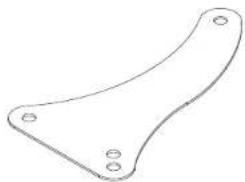
1.2 U-bracket including Mounting Plates

This U-bracket serves to mount VORTIS (2) speakers to walls and ceilings. You can aim and align cabinets using a combination of speaker tilt and/or wall plate. The U-bracket comes with two mounting plates included with delivery that attach it to the enclosure. For each model of loudspeaker a different U-bracket is available.
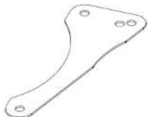
1.3 Speaker Tilt with Angular Alignment

This adapter adjusts the tilt angle of VORTIS (2) cabinets in 5° steps up to a maximum of 45°. The U-bracket connects the enclosure and speaker tilt.
1.4 Wall Plate
This plate offers the possibility to mount the speakers to walls. It lets you rotate the enclosure in 5" steps. You need either the U-bracket in combination with the speaker tilt or just the VORTIS (2) cabinet's U-bracket to attach the cabinet to the wall plate.
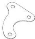
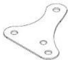
1.5 Cluster Plates
Speaker cabinets may be clustered to change their directivity. This cluster plate lets you array cabinets vertically and horizontally. You will need the extension plate to cluster more than two enclosures.
Note: The VR(2)-10810 requires a different cluster plate!
The 0° plate is suitable for the 40° × 60° horn, and the 10° plate for 60° × 40° and 55° × 30° horns.
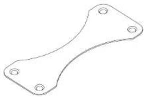
0° VORTIS (2) cluster plate

10° VORTIS (2) cluster plate

0° VR(2)-10810 cluster plate
10° VR(2)-10810 cluster plate
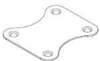
1.6 Plate for Cluster Panels
This extension serves as a shim for overlapping cluster plates. It is necessary when clustering more than two VORTIS (2) cabinets.
0° VORTIS (2) extension plate for cluster panels
10° VORTIS (2) extension plate for cluster panels
0° VR(2)-10810 extension plate for cluster panels
10° VR(2)-10810 extension plate for cluster panels
1.7 TB-R Tilt Bracket
This universal tilt bracket serves to attach any VORTIS (2) speaker cabinet (apart from model no. 10810) to trusses, ceilings, wall mounts and cross beams.

2 Installation Options
Ceiling/ wall mounted U-bracket
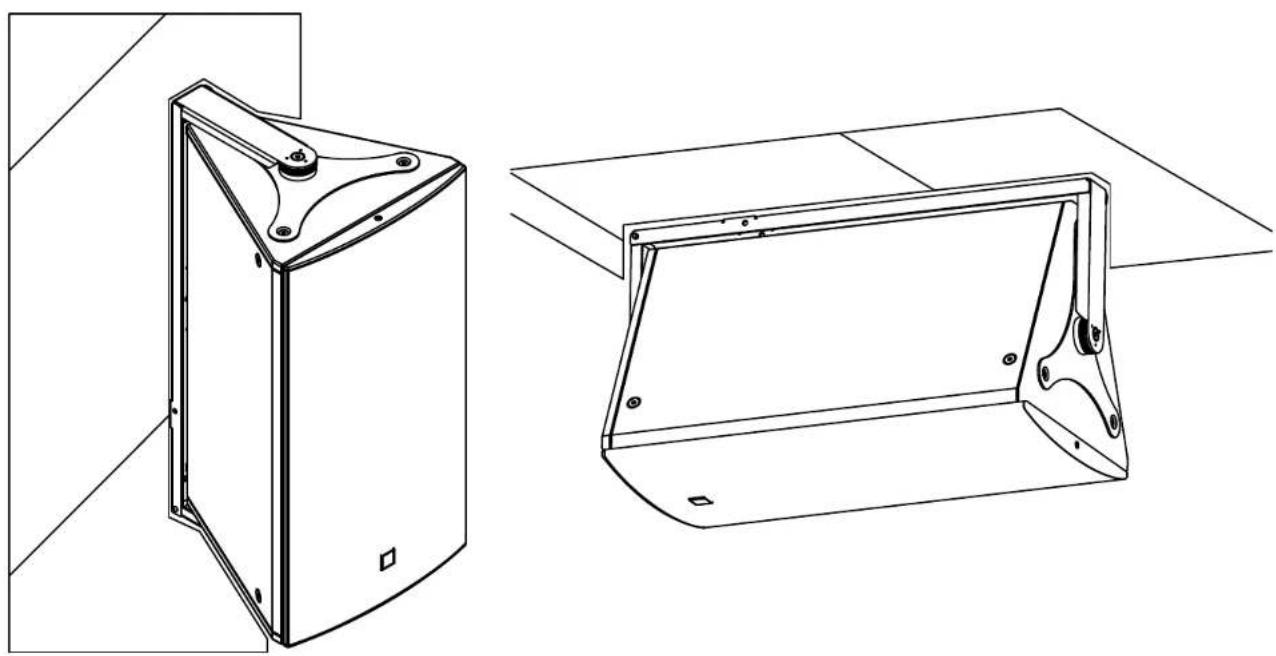
Ceiling/ wall mounted U-bracket and speaker tilt
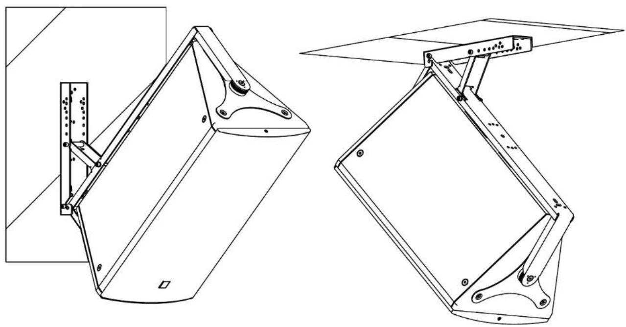
Ceiling/ wall mounted U-bracket, speaker tilt, and wall plate

3 General Installation Instructions
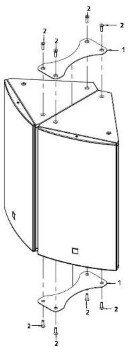
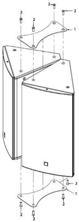
3.1 Attaching Mounting Plates to VORTIS (2) Enclosures
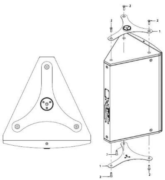
Heads up: The screws may be a bit tight if there is any paint residue on the threads.
| pos. description qty. | ||
| 1 mounting plate 2 | ||
| 2 hexagon socket countersunk head screw. M10x35 6 | ||
3.2 Attaching U-brackets to VORTIS (2) Enclosures
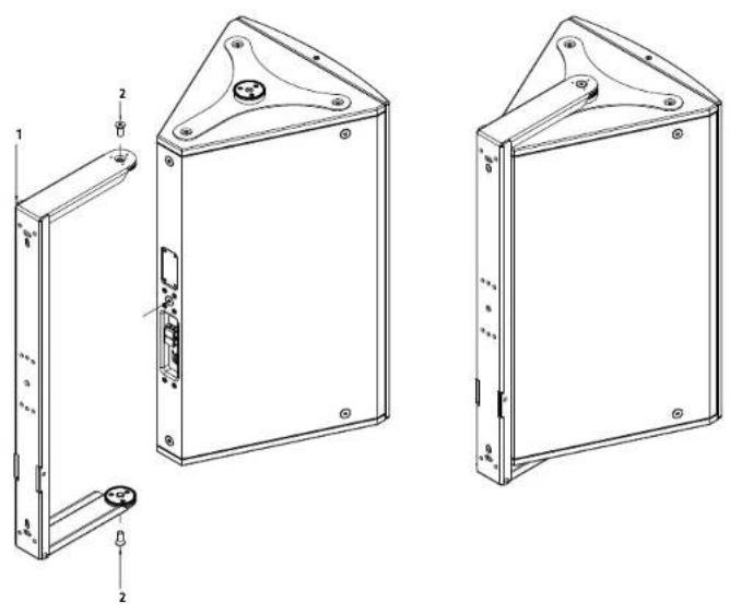
Note: You must attach the mounting plates before you can connect the U-bracket to the cabinet (see 3.1).
| pos. description qty. | ||
| 1 U-bracket 1 | ||
| 2 hexagon socket countersunk head screw, M10x25 2 | ||
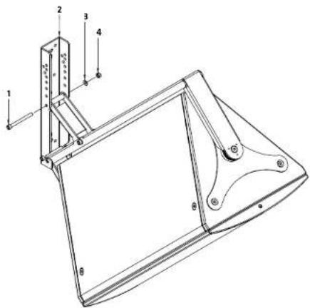
3.3 Attaching the Angular Alignment
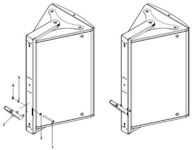
pos. description qty.
| 1 hexagon socket head cap screw DIN912 M8x90 1 | |
| 2 angular alignment 1 | |
| 3 washer, form A, D = 8.4 mm, black 2 | |
| 4 self locking hexagon nut with plastic insert, M8 1 |
3.4 Connecting Enclosures to the Speaker Tilt (without the Wall Plate)

Tip: Mount the speaker tilt to the wall first. Then it will be easier to lift the cabinet and slide the attached U-bracket into the retaining fixture.
| pos. description qty. | ||
| 1 | hexagon socket head cap screw DIN912 M8x50 1 | |
| 2 | speaker tilt | 1 |
| 3 | washer, form A, D = 8.4 mm, black 1 | |
| 4 self# | locking hexagon nut with plastic insert, M8 1 | |
Adjusting the Speaker Tilt Angle
Note: You can select different tilt angles by choosing different holes.
pos. description qty.
| 1 hexagon socket head cap screw DIN512 M8x30 1 | |
| 2 speaker tilt 1 | |
| 3 washer, form A, D = 8.4 mm, black 1 | |
| 4 self locking hexagon nut with plastic insert, M8 1 |
3.5 Mounting the Speaker Tilt to the optional Wall Plate
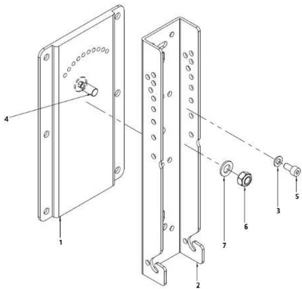
| pos. | description | qty. |
| 1 wall | plate 1 | |
| 2 | speaker tilt | 1 |
| 3 | washer, form A, D = 8.4 mm, black | 1 |
| 4 | countersunk head screw M12x30, zinc plated | 1 |
| 5 | hexagon socket countersunk head screw, M8x16, zinc | 1 |
| 6 | self locking hexagon nut with plastic insert M12, zinc plated | 1 |
| 7 | flat washer 12mm | 1 |
3.6 Installing the TB-R tilt bracket
- Place the cabinet on a stable surface.
- Remove the three countersunk M10 hex-head screws from the top panel using a 6 mm hex key or screwdriver bit. You will use these screws to attach the TB-R (fi g. 1).
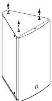
Fig. 1
Heads up: The screws may be a bit tight if there is any paint residue on the threads.
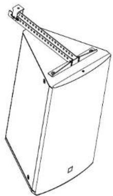
3. Align the TB-R with the three holes on the top of the cabinet and fasten it in place using the M10 screws that you just removed (Fig. 2).

Fig. 2
- The carriage on the topside of the TB-R provides a 10 mm hole that serves to attach the cabinet to truss bars, ceiling brackets and the like using suitable rigging/fastening devices.
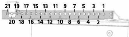
- Slide this carriage to any one of the 21 paired holes to shift the cabinet's center of gravity and hang the cabinet at the desired angle. The table on the back page lists the available tilt angles.
Heads up! Never move the carriage without first placing the cabinet on a firm base.
- To move the carriage to another pair of holes, simply remove the cotter pin and bolt (Fig. 3) and slide it to the desired position (Fig. 4). Reinsert the bolt and cotter pin to secure the carriage. Make sure the cotter pin is properly seated.
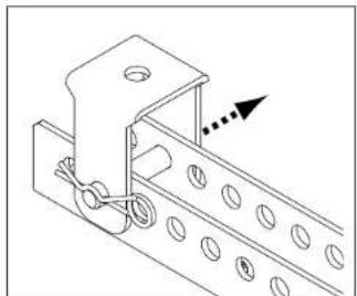
Fig. 3
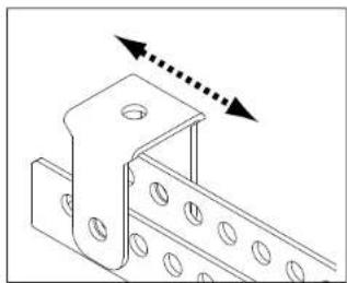
Fig. 4
Heads up! Be sure to check if national, regional or local regulations call for a secondary safety or arrest wire.
Installing the AP-10 B
The included AP-10 B serves to attach a secondary safety or as an additional pick point that lets you to tilt the speaker at an even steeper angle.
To install it, remove one of the M10 countersunk screws on the rear of the VORTIS (2) cabinet (fi g. S) and then attach the AP-10 B to that point using the included hex-head screw. The safety washer goes between the head of the screw and the AP-10 B.
To use the AP-10 B for a secondary safety or arrest wire, pick a point closest to the top of the cabinet and install it there. To use the AP-10 B as an additional suspension/pick point, choose a screw hole closest to the bottom of the cabinet and it install there.

Fig. 5
Tilt angles
*The paired holes on a mounted TB-R are numbered front (near the acoustic baffle) to back (rear of the speaker) as depicted below. The values were determined using VORTIS (2) cabinets. They also apply to the corresponding VORTIS (2) models.
4 Clustering VORTIS (2) Enclosures
4.1 Clustering two VORTIS (2) Enclosures with the 0° Cluster Plate
| pos. description qty. | ||
| 1 cluster plate 0° 2 | ||
| 2 hexagon socket countersunk head screw, M10x35 8 | ||
4.2 Clustering two VORTIS (2) Enclosures with the 10° Cluster Plate
| pos. description qty. | ||
| 1 cluster plate 10° 2 | ||
| 2 | hexagon socket countersunk head screw, M10x35 | 8 |
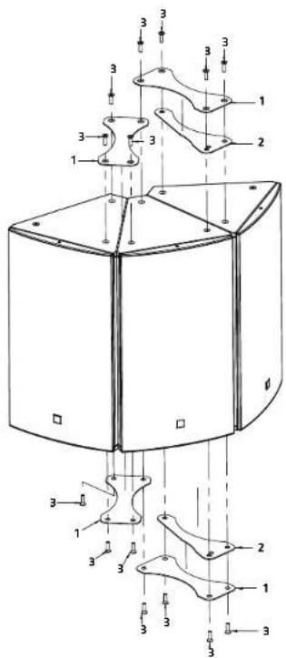
4.3 Clustering two VORTIS (2) Enclosures with the Cluster Plate and U-bracket

Caution: The following table with Information on the maximum load capacity of the U-brackets must be considered.
Under no circumstances should more than the specified quantities of VORTIS (2) speakers be attached to them and mounted above audience.
Failing to do so will voids the manufacturer's operating permit.
| Speaker cabinet | max. load capacity of U-bracket with central suspension (1-point) | max. load capacity of U-bracket with double lateral suspension (2-point) |
| VR(2)-10810 | 3 | 3 |
| VR(2)-11210 | 2 | 3 |
| VR(2)-11510 | 2 | 2 |
| VR(2)-11214 | 2 | 2 |
| VR(2)-11514 | 1 | 2 |
| VR(2)-21214 | 0 | 1 |
| pos. description qty. | |
| 1 U-bracket 1 | |
| 2 mounting plate 2 | |
| 3 cluster plate 2 | |
| 4 extension plate for cluster panels 2 | |
| 5 hexagon socket countersunk head screw, M10x35 10 | |
| 6 hexagon socket countersunk head screw, M10x25 2 | |
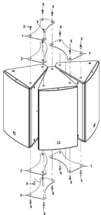
4.4 Clustering three VORTIS Enclosures with the 0° Cluster Plate
| pos. description qty. | ||
| 1 cluster plate 0° 4 | ||
| 2 extension plate for cluster panels 0° 2 | ||
| 3 hexagon socket countersunk head screw, M10x35 14 | ||
4.5 Clustering three VORTIS Enclosures with the 10° Cluster Plate
| pos. description qty. | |
| 1 cluster plate 10° 4 | |
| 2 extension plate for cluster panels 10° 2 | |
| 3 hexagon socket countersunk head screw. M10x35 14 | |
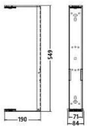
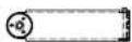
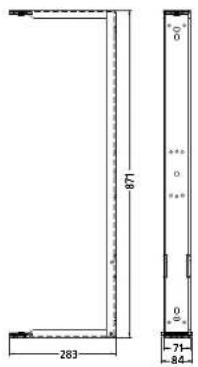
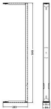
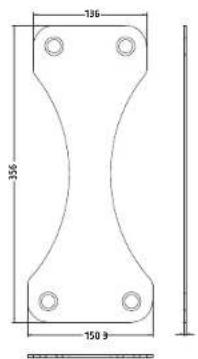
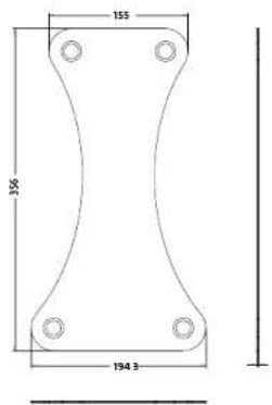
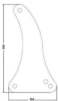
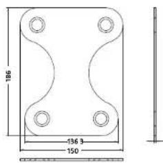
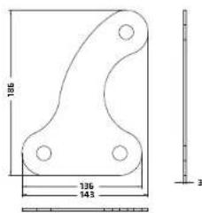
5 Dimensional Drawings of ComponentParts
(all dimensions in mm)
U-brackets

U-bracket VR(2)-10810
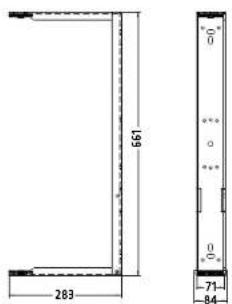
U-bracket VR(2)-11210
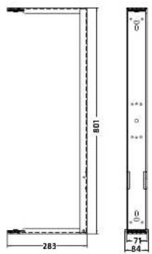

U-bracket VR(2)-11214
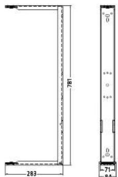

U-bracket VR(2)-11510
U-bracket VR(2)-11514
U bracket VR(2) 21214
Mounting Plates

Mounting plate VORTIS (2)
Wall Plate
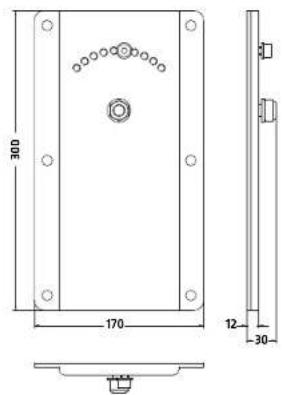
Speaker Tilt Angle


Mounting plate VR(2)-10810
Cluster Plates VORTIS (2)
Cluster plate 0° VORTIS (2)
Cluster plate 10° VORTIS (2)
Extension Plate for Cluster panels
VORTIS (2)

Cluster extension plate for cluster panels 0" VORTIS (2)
Cluster extension plate for cluster panels 10° VORTIS (2)
Cluster Plates VR(2)-10810
Cluster plate 0" VR(2)-10810

Cluster plate 10° VR(2)-10810
Extension Plate for Cluster panels
VR(2)-10810
Cluster extension plate for cluster panels 0° VR(2)-10810

Cluster extension plate for cluster panels 10" VR(2)-10810
6 Aligning Horns
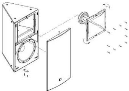
You can rotate all VORTIS series horns 90° to adjust their coverage pattern.
Tool: hex wrench size 3 and 4
- Unscrew the hex head bolts holding the front grille in place and remove the front grille.
- Unfasten the screws holding the horn in place and rotate the horn.
Note: Before you can turn the VR(2)-10810's horn you must first remove the top L-bracket that holds the front grille in place (see figure 6.2).

- Reinstall the horn
- Reattach the metal L-bracket (on the VR(2)-10810 only).
- Fasten all screws, turning them clockwise until the heads are flush with the recesses.
- Replace the front grille and fasten the hex head bolts, tightening until the heads are flush with the recesses.
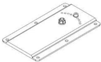
7 Ball Impact Safety
A simple modification to the VORTIS series cabinets protects speakers against ball impact in compliance with DIN 18032-3. To this end, install the metal strip included in the box as shown in the following diagram.

Caution: Be sure to take all the precautions necessary to prevent bolted connections from loosening, for example, by using thread-lock adhesive.
In all VORTIS 2 (EN 54) loudspeaker systems, the ball impact protection plate is pre-mounted as standard.
| pos. description qty. | ||
| 1 safety plate VORTIS (2) 1 | ||
| 2 hexagon socket countersunk head screw, MGx25 2 | ||
VORTIS / VORTIS 2 (EN 54)

HK Audio ® • Postfach 1509 • 66595 St. Wendel • Germany • info@hkaudio.com • www.hkaudio.com
International Inquiries: fax +49-68 51-905 215 • international@hkaudio.com
- MOUNTING ACCESSORIES
- GENERAL NOTES ON SAFETY FOR LOUDSPEAKER SYSTEMS
- TABLE OF CONTENTS
- 1 INDIVIDUAL COMPONENTS
- 1.5 CLUSTER PLATES
- 1.6 PLATE FOR CLUSTER PANELS
- 1.7 TB-R TILT BRACKET
- 2 INSTALLATION OPTIONS
- 3 GENERAL INSTALLATION INSTRUCTIONS
- 3.1 ATTACHING MOUNTING PLATES TO VORTIS (2) ENCLOSURES
- 3.2 ATTACHING U-BRACKETS TO VORTIS (2) ENCLOSURES
- 3.3 ATTACHING THE ANGULAR ALIGNMENT
- 3.4 CONNECTING ENCLOSURES TO THE SPEAKER TILT (WITHOUT THE WALL PLATE)
- ADJUSTING THE SPEAKER TILT ANGLE
- 3.5 MOUNTING THE SPEAKER TILT TO THE OPTIONAL WALL PLATE
- 3.6 INSTALLING THE TB-R TILT BRACKET
- INSTALLING THE AP-10 B
- 4 CLUSTERING VORTIS (2) ENCLOSURES
- 4.1 CLUSTERING TWO VORTIS (2) ENCLOSURES WITH THE 0° CLUSTER PLATE
- 4.2 CLUSTERING TWO VORTIS (2) ENCLOSURES WITH THE 10° CLUSTER PLATE
- 5 DIMENSIONAL DRAWINGS OF COMPONENTPARTS
- 7 BALL IMPACT SAFETY
- VORTIS / VORTIS 2 (EN 54)
Brand : HK AUDIO
Model : Vortis 2 VR2-11210
Category : Loudspeaker