
Control Station Panel - Industrial control device HAYWARD - Free user manual and instructions
Find the device manual for free Control Station Panel HAYWARD in PDF.
| Product Type | Industrial control device for swimming pool |
| Brand | Hayward |
| Model | Control Station Panel |
| Main Functions | Filtration control (manual, automatic, smart, intelligent, heating), electrolysis/hydrolysis, lighting, auxiliary relays, pH control, Redox, free chlorine, conductivity, temperature, WiFi connectivity |
| Power Supply | 230 V AC / 50 Hz (standard estimate) |
| Dimensions (W x H x D) | 300 x 200 x 150 mm (estimate) |
| Weight | 2 kg (estimate) |
| Protection Rating | IP54 (estimate, to be confirmed) |
| Housing Material | ABS plastic (estimate) |
| Display | TFT color screen |
| User Interface | Keys (Plus, Minus, OK, Up, Down, Back/Exit) |
| Filtration Modes | Manual, Automatic (3 timers), Smart (adaptive temperature), Timed heating, Intelligent (minimization of filtration hours) |
| Electrolysis/Hydrolysis Management | Chlorine production (g/h) or disinfectant (%), shock mode, Redox control |
| Compatible Probes | pH, Redox, Free chlorine, Conductivity, Temperature |
| Connectivity | WiFi via external module (www.vistapool.es) |
| Auxiliary Relays | Up to 4, programmable (fountains, garden lighting, etc.) |
| Lighting | Manual mode, automatic (with frequency), LED spots with color change |
| Safety | Disconnect before intervention, installation by qualified electrician, RCD 30 mA, isolation transformer, short-circuit protection |
| Maintenance and Cleaning | Filter cleaning (backwash), monthly calibration of probes (pH, Redox, free chlorine, conductivity, temperature) |
| Spare Parts and Repairability | Use original Hayward parts; 2-year warranty on electronic housing and supports, 6 months on probes, 8000 hours on titanium cell (pro-rata replacement) |
| Operating Temperature | 0-100 °C (probe), -10 to 50 °C (housing, estimate) |
| Electrical Standards | Compliant with national standards (C 15-100, BS7671, VDE, etc.) |
Frequently Asked Questions - Control Station Panel HAYWARD
User questions about Control Station Panel HAYWARD
0 question about this device. Answer the ones you know or ask your own.
Ask a new question about this device
Download the instructions for your Industrial control device in PDF format for free! Find your manual Control Station Panel - HAYWARD and take your electronic device back in hand. On this page are published all the documents necessary for the use of your device. Control Station Panel by HAYWARD.
USER MANUAL Control Station Panel HAYWARD
Domestic and Industrial devices
4. MEDIDAS / Setpoints


WARNING - Disconnect the equipment from the mains supply before any intervention.
WARNING - All electrical connections must be carried out by a qualified approved electrician in accordance with the standards currently in force in the country of installation.
| F NF C 15-100 GB BS7671:1992 | |||
| D DIN VDE 0100-702 EW SIST HD 384-7-702.S2 | |||
| A ÖVE 8001-4-702 H MSZ 2364-702:1994 / MSZ 10-533 1/1990 | |||
| E UNE 20460-7-702 1993, REBT ITC-BT-31 2002 M MSA HD 384-7-702.S2 | |||
| IRL IS HD 384-7-702 | PL | TS IEC 60364-7-702 | |
| I CEI 64-8/7 | CZ | CSN 33 2000 7-702 | |
| LUX 384-7.702 S2 | SK | STN 33 2000-7-702 | |
| NL NEN 1010-7-702 | SLO | SIST HD 384-7-702.S2 | |
| P RSIIUEE | TR TS | IEC 60364-7-702 |
WARNING - Check that the device is plugged into a power outlet that is protected against short-circuits. The device must also be powered via an isolating transformer or a residual current device (RCD) with a nominal operating residual current not exceeding 30mA .
WARNING - Ensure that children cannot play with the device. Keep your hands and any foreign object away from openings and moving parts.
WARNING - Check that the supply voltage required by the product corresponds to the voltage of the distribution network and that the power supply cables are suitable for the product power supply.
WARNING - Chemicals can cause internal and external burns. To avoid death, serious injury and/or damage to equipment, wear personal protective equipment (gloves, goggles, mask, etc.) when servicing or maintaining this device. This device must be installed in an adequately ventilated place.
WARNING - To reduce the risk of electric shock, do not use an extension cable to connect the device to the mains. Use a wall socket.
WARNING - Carefully read the instructions that appear in this manual and on the device. Failure to comply with the instructions can cause injuries. This document must be given to every pool user, who should keep it in a safe place.
WARNING - This appliance can be used by children aged 8 years and over and by people with reduced physical, sensory or mental capabilities, or those who lack experience or knowledge, if they are supervised correctly or if they have been given instructions concerning safe use of the appliance and understand the hazards involved. Children must not play with the device. User maintenance and cleaning must not be carried out by unsupervised children.
WARNING - Use only original Hayward parts.
WARNING - If the power supply cable is damaged, it must be replaced by the manufacturer, the after-sales service or similarly qualified persons to avoid danger.
WARNING - The device must not be used if the power cord is damaged. An electric shock could occur. A damaged power cord must be replaced by the after-sales service or similarly qualified persons to avoid danger.
GENERAL INSTALLATION GUIDE
DOMESTIC & INDUSTRIAL DEVICES
For complete technical information of your device, access the following link: www.smartswim.net
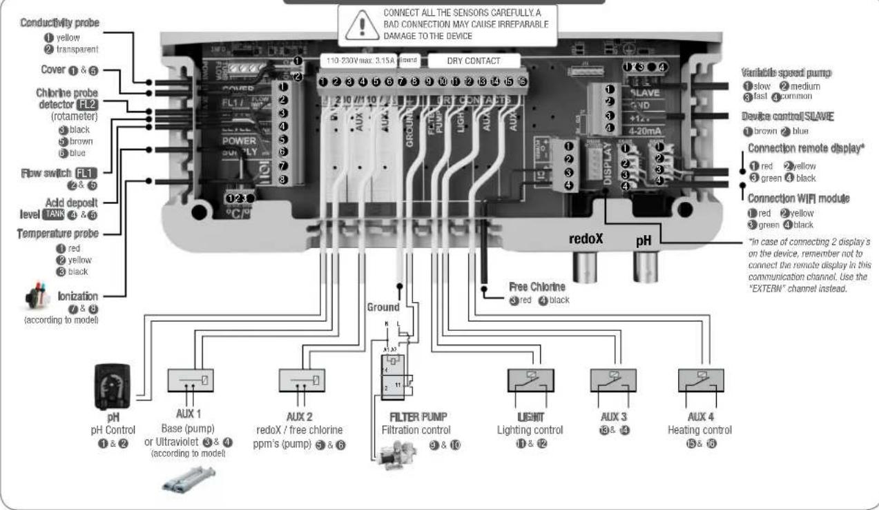
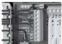
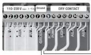
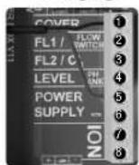
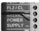
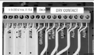
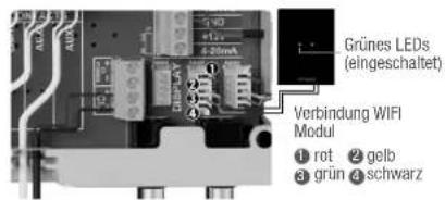
1. ELECTRONIC BOX INTERNAL CONNECTIONS
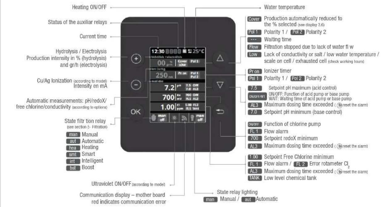
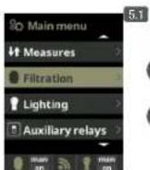
2. MAIN SCREEN

PLUS key
Modify value/selection

MINUS key
Modify value/selection

OK key
Select/confir

UP key
Navigation up

DOWN Key
Navigation down

RETURN/ESCAPE key
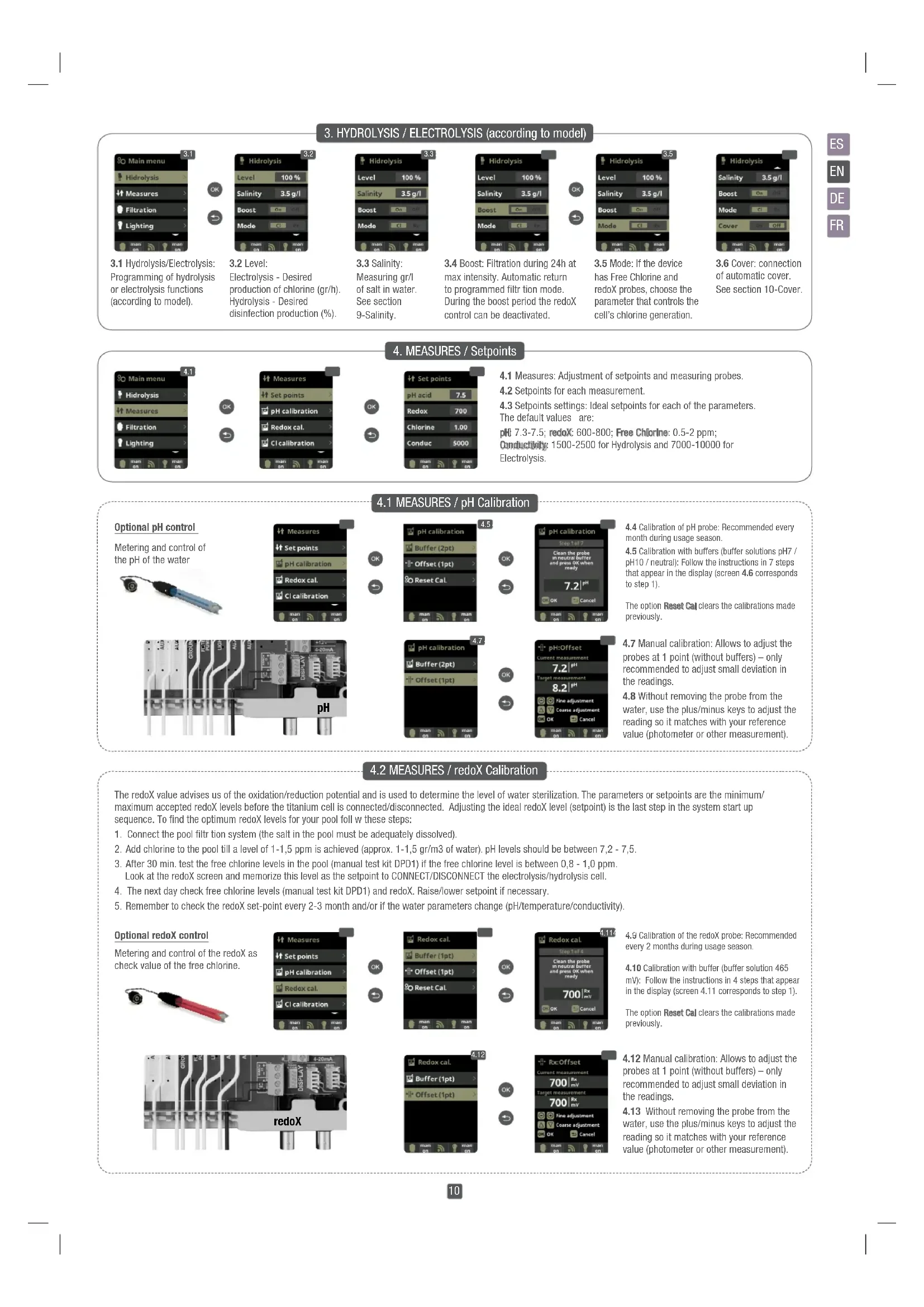
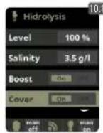
3. HYDROLYSIS / ELECTROLYSIS (according to model)
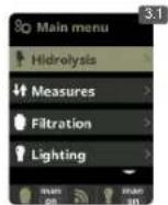

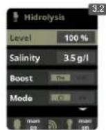
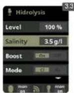
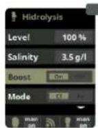

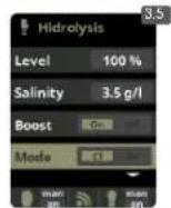
3.1 Hydrolysis/Electrolysis: Programming of hydrolysis or electrolysis functions (according to model).
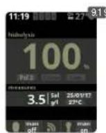
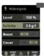
3.2 Level:
Electrolysis - Desired production of chlorine (gr/h). Hydrolysis - Desired disinfection production (%)
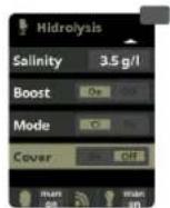
3.3 Salinity:
Measuring gr/l of salt in water. See section 9-Salinity.
3.4 Boost: Filtration during 24h at max intensity. Automatic return to programmed filtrion mode. During the boost period the redox control can be deactivated.
3.5 Mode: If the device has Free Chlorine and redoX probes, choose the parameter that controls the cell's chlorine generation.
3.6 Cover: connection of automatic cover. See section 10-Cover.
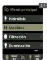
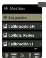
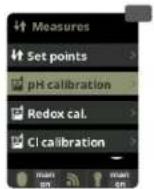
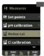
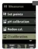
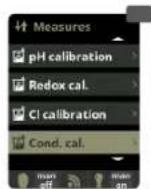
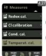
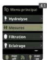
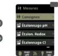
4. MEASURES / Setpoints
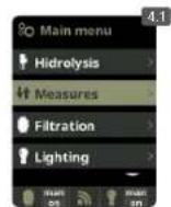

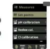


4.1 Measures: Adjustment of setpoints and measuring probes.
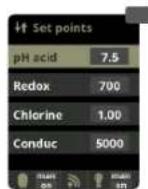
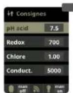
4.2 Setpoints for each measurement
4.3 Setpoints settings: Ideal setpoints for each of the parameters. The default values are:
pH 7.3-7.5; redox: 600-800; Free Chlorine: 0.5-2 ppm;
Conductivity: 1500-2500 for Hydrolysis and 7000-10000 for
Electrolysis.
4.1 MEASURES / pH Calibration
Optional pH control
Metering and control of the pH of the water
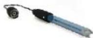


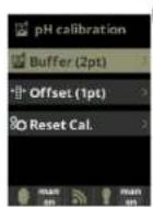


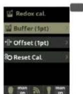
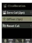
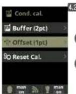
4.4 Calibration of pH probe: Recommended every month during usage season.
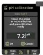
4.5 Calibration with buffers (buffer solutions pH7 / pH10 / neutral): Follow the instructions in 7 steps that appear in the display (screen 4.6 corresponds to step 1).
The option Reset Cal clears the calibrations made previously.
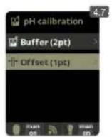


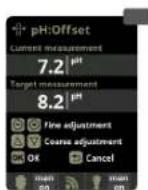
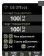
4.7 Manual calibration: Allows to adjust the probes at 1 point (without buffers) - only recommended to adjust small deviation in the readings.
4.8 Without removing the probe from the water, use the plus/minus keys to adjust the reading so it matches with your reference value (photometer or other measurement).
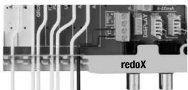
4.2 MEASURES / redoX Calibration
The redox value advises us of the oxidation/reduction potential and is used to determine the level of water sterilization. The parameters or setpoints are the minimum/ maximum accepted redoX levels before the titanium cell is connected/disconnected. Adjusting the ideal redoX level (setpoint) is the last step in the system start up sequence. To find the optimum redoX levels for your pool foll w these steps:
- Connect the pool filtration system (the salt in the pool must be adequately dissolved).
- Add chlorine to the pool till a level of 1-1,5 ppm is achieved (approx. 1-1,5 gr/m3 of water). pH levels should be between 7,2 - 7,5.
- After 30 min. test the free chlorine levels in the pool (manual test kit DPD1) if the free chlorine level is between 0,8 - 1,0 ppm.
Look at the redox screen and memorize this level as the setpoint to CONNECT/DISCONNECT the electrolysis/hydrolysis cell. - The next day check free chlorine levels (manual test kit DPD1) and redox. Raise/lower setpoint if necessary.
- Remember to check the redox set-point every 2-3 month and/or if the water parameters change (pH/temperature/conductivity).
Optional redox control
Metering and control of the redox as check value of the free chlorine.


4.9 Calibration of the redoX probe: Recommended every 2 months during usage season.
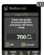
4.10 Calibration with buffer (buffer solution 465 mV): Follow the instructions in 4 steps that appear in the display (screen 4.11 corresponds to step 1).
The option Reset Cal clears the calibrations made previously.
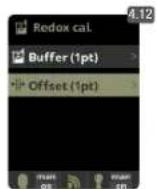


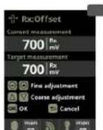
4.12 Manual calibration: Allows to adjust the probes at 1 point (without buffers) - only recommended to adjust small deviation in the readings.
4.13 Without removing the probe from the water, use the plus/minus keys to adjust the reading so it matches with your reference value (photometer or other measurement).
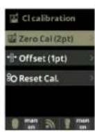
4.3 MEASURES / Free Chlorine calibration
Optional Free Chlorine control
Metering and control in ppm of the free chlorine of the water.
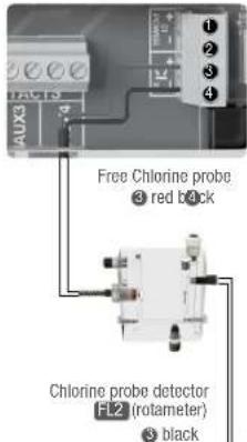
brown blue
In case of using a Variable Speed Pump, calibrate the probe using the most common filtration speed.
OK
4.15

black brown blue
0
OK
4.14 Calibration of the Free Chlorine probe: Recommended every month during usage season.
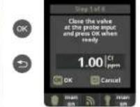
4.15 Calibration with buffer (photometer DPD01): Follow the instructions in 6 steps that appear in the display.
4.16 Step 1 of 6 - Calibrate Cl at 0 ppm (offset): Close the water flow through the probe and wait until the reading is less than 0, 10 ppm. Wait between 5 to 60 min. Press OK when the reading is close to 0.
The option Reset Cal clears the calibrations made previously.
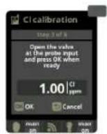
4.17 Step 3 of 6 - Calibrate Cl: Open the water flow until achieving 80-100 liters/hour. Wait until obtaining a stable reading of ppm. Wait between 5 to 20 min. Press OK when the reading is stable.
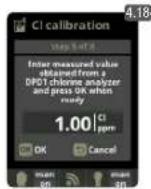
4.18 Step 5 of 6 - Establish the real ppm values with the plus/minus keys according to your analysis result of DPD1 (free chlorine).
4.19 Step 6 of 6 - If this screen is not shown repeat the calibration process.
4.20 and 4.21 Manual calibration: Open de water fl w and set the fl wrmeter (rotameter) at the right level of fl w (80-100l/h). Wait some minutes until the current level is stable. With the plus/minus keys, insert manually the water chlorine level (use a manual DPD1 test kit). Press OK when the DPD1 value is correct on display (target measurement).
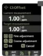
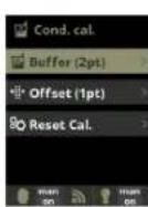
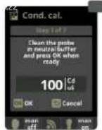
4.4 MEASURES / Conductivity calibration
Optional Conductivity probe
Metering and control of the conductivity of the water in Msiemens.

OK
OK
4.22 Calibration of the Conductivity probe: Recommended every month during usage season.
4.23 Calibration with buffer (buffer solution 1413 S/ 12880 S/ neutral): Follow the instructions in 7 steps that appear in the display (screen 4.24 corresponds to step 1).
The option Reset Calcules the calibrations made previously.
Conductivity probe
.25
OK
4.25 Manual calibration: Allows to adjust the probes at 1 point (without buffers) - only recommended to adjust small deviation in the readings.
4.26 Without removing the probe from the water, use the plus/minus keys to adjust the reading so it matches with your reference value (photometer or other measurement).
4.5 MEASURES / Temperature calibration
Optional Temperature
Temperature probe necessary to activate the filtration modes: heating, intelligent, smart.
Temperature
probe
red
yellow
yellow black
Black
OK
OK
4.28
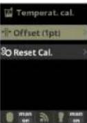
4.27 and 4.28 Temperature
calibration: To set difference between the measured value of the probe and the actual temperature, use the plus/minus and up/down keys. Set to the actual temperature of the probe and press OK.
The option Reset Calibrates the calibrations made previously.
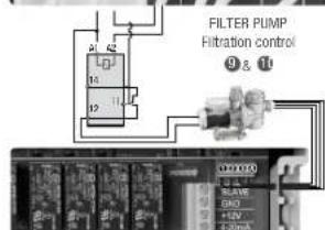
5. FILTRATION / Manual mode
Setup and connection of a Variable Speed Pump, see section 13 - Variable Speed Pump
OK
m = 311
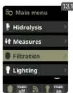
5.1 Filtration:
Configurion control of the filter pump To set, select Filtration and confirm by pressing OK The mode selection is done in Mode line with the plus/minus keys.
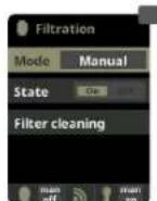
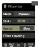
5.2 Manual:
Manually turns ON/OFF the filtr ion process. No timing or additional functions. The State line indicates whether the filtrion pump is ON.
See section Filter Cleaning below.
5.1 FILTRATION / Automatic mode
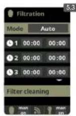
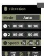
5.3 Automatic (or with timer):
In this mode the filtration is switched in accordance with a timer that allows to adjust the start and end of the filtration. Timers always operate daily, in cycles of 24 hours.
To set the ON/OFF times (up to 3 possible time programmable), select with the up/down keys in the timer line you want to change (1-3).
The plus/minus keys opens the selected start time field. Set the time with plus/minus keys. Scroll with the up key to the minute field and set it up with plus/minus keys. To confirm press OK and to cancel press return/sc pe. To set the OFF timer, proceed accordingly.
See section Filter Cleaning below.
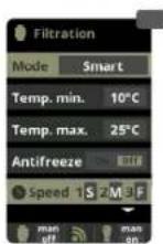
5.2 FILTRATION / Smart mode
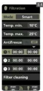
5.4 Smart: This mode uses, as a basis, the automatic or timer mode, with its 3 intervals of filtration, but adjusting the filtration time in function of the water temperature. For that reason 2 parameters of temperature are provided: The maximum temperature, from which on the filtration times will be the ones from the timer setting. The minimum temperature: below this value the filtration time will be reduced to 5 minutes, which is the minimum working time. Between these 2 temperatures the filtration times will climb linearly.
Use the plus/minus keys to set the desired minimum and maximum temperatures.
There is an option to activate the antifreeze mode in which the filtration will start if the water temperature is below 2^ .
To set the ON/OFF times (up to 3 possible time programmable), follow the instructions of the Automatic Mode.
See section Filter Cleaning below.
- Note: Mode only visible if the option to use temperature probe and/or heating is activated in the "Installer Menu".
5.3 FILTRATION / Heating mode
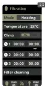
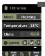
5.5 Timed heating with option of climatization*: This mode acts equally to the automatic mode, but besides it includes the option to work on a relay to control the temperature. The desired temperature is set in this menu, and the system works with a hysteresis of 1 degree (example: the setting temperature is 23^ C, the system will activate itself when the temperature goes below 22^ C and will not stop before it passes 23^ C). Use the plus/minus keys to set the desired temperatures and ON/OFF of the Heating.
Clima OFF: The heating only works within the set filtrion periods.
Clima ON: Keeps the filtration working when the filtration period is finished if the water temperature is below the setting temperature. When the setting temperature is reached the filtration and the heating will stop and will not switch on till the next programmed filtration period.
To set the ON/OFF times (up to 3 possible time programmable), follow the instructions of the Automatic Mode.
See section Filter Cleaning below.
- Note: Mode only visible if the option to use temperature probe and/or heating is activated in the "Installer Menu".
5.4 FILTRATION / Intelligent mode
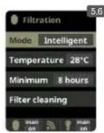
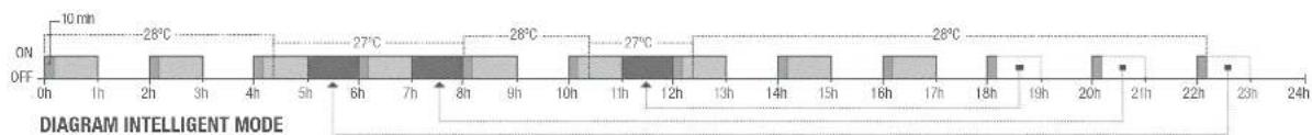
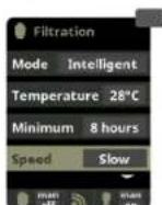
5.6 Intelligent*: In this mode the user has 2 working parameters to guaranty the desired water temperature with a minimum of filtr tion hours: You select the desired water temperature and the minimum filtration time (minimum of 2 hours and maximum of 24 hours). The device divides the selected "minimum filtration time" in 12 fragments which start up every 2 hours. If one of these fragments finishes without the temperature reaching the desired level, the filtration/heating continues until the desired temperature is accomplished. In order to keep the filtration-electricity-cost to a minimum, this additional filtration time is subtracted from the following fragments of the "minimum filtration time". The first 10 minutes of each fragment will not be subtracted.
Example (see diagram): Minimum temperature = 28^ and minimum filter tion time = 12 hours.
The desired water temperature and the minimum filtr ion time is set with the plus/minus keys .
See section Filter Cleaning below.
* Note: Mode only visible if the option to use temperature probe and/or heating is activated in the "Installer Menu".
5.5 FILTRATION / Filter cleaning
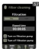
5.7 Filter cleaning mode (and pool cleaning by suction): From this menu (accessible from any Filtration mode) It can be easily performed a backwashing cleaning of the sand flite. Activating this menu from any filtration mode (Manual, Automatic, Heating, Smart, Intelligent), will disconnect electrolysis/hydrolysis cell. Then proceed as follows:
- Put the filter pump OFF with plus/minus keys.
- Place the filtrion pump valve in backwashing cleaning position.
- Put back ON in the filtration pump. Control the time that lasted the backwash cleaning on the clock display. Make sure it has made adequate and complete backwash of your filte.
- When finished the backwashing leaning, again turn OFF the filtration pump and put back the valve in the filtering position. If you wish, now you can perform a rinse cycle.
- Proceed as backwashing cleaning, this time placing the filtration pump valve in the rinsing position.
- When leaving the Filter Cleaning menu, the system will be back to the previous programmed mode.
OK
OK
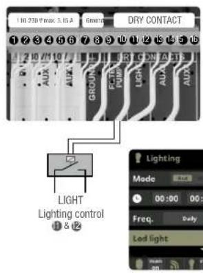
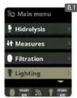
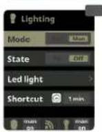
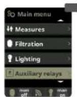
6.1 Lighting
6.2 Manual Mode (ON/OFF).
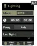
6.3 Automatic Mode: Shut lights ON/OFF according to a timer. The timers can be configured with a frequen y: Daily; Every 2 days; Every 3 days; Every 4 days; Every 5 days; Weekly; Every 2 weeks; Every 3 weeks; Every 4 weeks.
6.4 LED spotlight: In case of having installed led lights in your pool, use this menu to set the lighting.
6.5 From this menu you can change the color of the lights in your pool. Select the length of the sign in seconds in Pulse length and press Next Program option to apply the pulse. Refer to your LED spotlight manual to set its different colors.
6.6 Shortcut: From main screen press "minus" to activate lighting during selected time.
7. AUXILIARY RELAYS
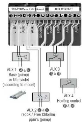
The auxiliary relays are configured by default. If you want to reassign the relays for other accessories, you must access the "Service Menu". Contact your authorized installer.
OK
OK
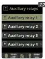
7.1 Auxiliary relays
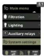
7.2 It is possible to control up to 4 extra auxiliary relays (water features, fountains, automatic irrigation systems, built-in cleaning systems, air pumps for spas, garden lighting, etc.). This menu displays the relays which are still available on your device and allow configurat ion.
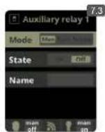
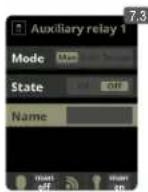
7.3 Manual mode (ON/OFF).
OK
7.
EV
7:
Renal
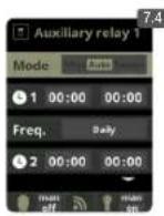
7.4 Automatic mode: ON/OFF according to a timer that adjust the start and end of the program. The timers can be configured with a frequen y: Daily; Every 2 days; Every 3 days; Every 4 days; Every 5 days; Weekly; Every 2 weeks; Every 3 weeks; Every 4 weeks.
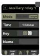
7.5 Timer mode: Working time is programmed in minutes. Each time the key on the front panel in relation to the relay is pressed, it will start up for the time programmed. This function is recommended for the timing of air pumps for spas.

7.1
to
7.6 Rename relays: It is possible to rename each auxiliary relay to suit the use you want to assign. By pressing the plus/minus keys, a pop-up keyboard will appear. Scroll up and down with the up/down keys and left to right with the plus/minus keys. To select a letter press the OK.
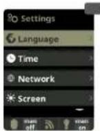
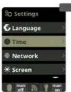
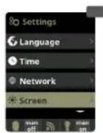
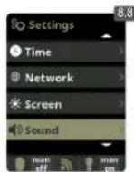
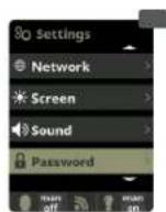
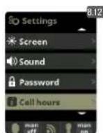
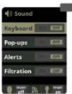
8. SYSTEM SETTINGS
OK
OK
1

OK
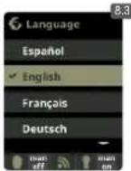
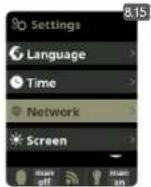
8.3 Setting of preferred language.
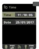
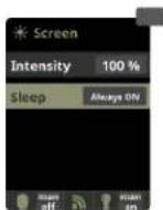
8.5 Setting of day and current time. 8.7 Setting of the intensity of the display lighting (0 - 100%) and programming its ON/OFF time.
OK
OK
3
OK

1

图
2x
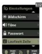
8.12
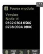
different modules. Includes (in parentheses), the number of performed resets of the electrolysis / hydrolysis hours counter.
System info: Information about the available software version of the TFT display and the power module. It also shows the ID node which is necessary for the configuration of the WIFI connection of the system.
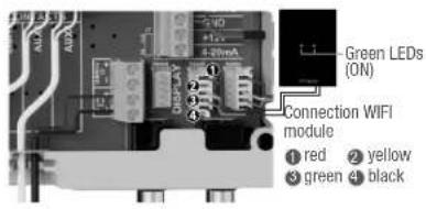
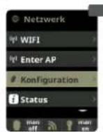
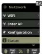
8.1 WIFI SETTINGS
OK
OK
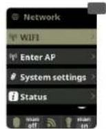
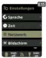
8.15 Internet: Once the WIFI module is connected, restart your unit. In the Settings menu will appear the Internet opt
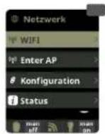
8.16 WIFI: Select WIFI to scan the available networks accessible to the module. The search will be done automatically. Select the desired network accessible to the WIFI module.
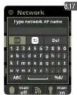
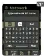
8.17 Enter the password in the pop-up keyboard. Scroll up and down with the up/down keys and left to right with the plus/minus keys. To select a letter press the OK.
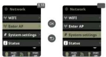
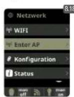
8.18 Select AP: Write manually the name and the password of the network selected.
8.19 Configurion: For a more detailed configuraton enter this menu or contact your installer.
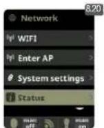
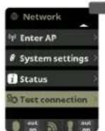
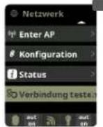
8.20 Status: Check the status of your connection.
8.21 Test connection: Check that your connection has been successfully established.
9.SALINITY*
OK
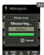
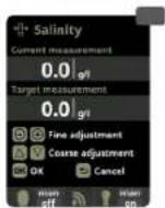
9.1 Salinity: The device shows a measurement of salt in water in g/l, as well as the date and water temperature of the last reading.
9.2 To acknowledge this measure, press OK in Salinity in the Electrolysis/Hydrolysis menu (the process takes between 2 and 5 minutes - display 9.4). You can adjust the system measure using an external salt measurer (display 9.5).
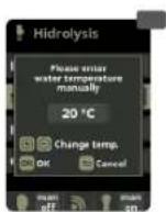
9.3 If you do not have a temperature probe, enter the value manually for greater accuracy. The lecture is influenced by many factors, like the water temperature or the pH. Remember to do the adjustment every 2-3 months.
- Attention: Option only available for some models.
Cover 1&5
#
OK
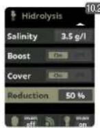
10.1 Cover: Connection of automatic cover.
10.2 Reduction of chlorine production in percent, when the pool cover is closed With the cover closed is not necessary for the system to run at 100% .With this parameter the system regulates the optimum amount of chlorine generation.
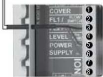
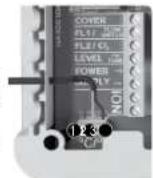
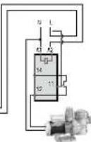
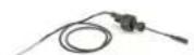
11. FLOW SWITCH
Optional Flow switch
Mechanic security fl w switch. Stops the hydrolysis/electrolysis and the dosing pumps if there is no water fl w.
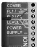
Flow switch F51 28
It is possible to add an external flw switch to the system.
Connect as shown in the image and contact your installer for activation. The titanium cell includes a gas flow sensor, you can combine both for better control.
12. LEVEL SENSOR (Tank)
Acid deposit level BANK 4 &5
Connect a level sensor to your device so you can control at all times the volume available in the tanks of chemicals that your system commonly uses. Contact your installer/provider to activate the sensor. This way you can ensure that the dosing pumps never run out of product and doses in vacuo, avoiding possible damages.
13. VARIABLE SPEED PUMP
Variable Speed Pump
1 slow 2 medium 3 fast 4 common
OK
13.1 Variable Speed Pump: To install a Variable Speed Pump contact your inst.
13.2 to 13.6 After connecting the pump, you can individually assign each filtration period a different speed
F: fast, M: medium and S: slow.
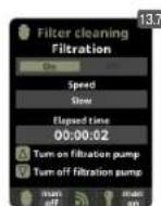
13.7 Filter cleaning: To clean the filter with a Variable Speed Pump, you should use the fastest speed.
1
m = 311
8.1 KONFIGURATION WIFI
OK
OK
OK
8.20
4. MESURES / Setpoints
OK
OK
4.3
pH: 7.3-7.5; redox: 600-800; Chlore libre: 0.5-2 ppm; Conductivity: 1500-2500 Hydrolyse, 7000-10000 Electrolyse.
4.1 MESURES / Calibrage pH
SUGAR VALLEY, S.L. holds a solid reputation due to the reliability of its products. Together with this recognition, our guarantee offers the user, following the terms described in this document, total security against any manufacturing default of its product or the original SUGAR VALLEY parts included in the same.
GARANTEE: The period of guarantee amounts to 2 years and starts with dispatch of delivery ex works. Guarantee covers cost of all components, spare parts and work employed on the mentioned product and all the parts and components whenever they are original SUGAR VALLEY products. Parts whose normal life expectancy, due to their function, is shorter than the legal term of warranty shall not be covered by our warranty. The guarantee does not cover damages due to natural wear, insufficient maintenance, neglect of operating means, chemicals and electrolytic influences, as well as other reasons beyond our responsibility. The guarantee lapses if the customer or third persons carry out modifications or repairs without our written consent. In case of possible violation of protection rights of third persons the customer has to keep us indemnified and free from legal actions. Damages inflicted by exterior causes to the system: flooding of the filter house, electric storm, etc... or/and spare parts (electrodes) or components used are not SUGAR VALLEY originals, will limit guarantee rights. Transport expenses for any repair are on the client.
LIMTED GUARANTEE : Paris whose normal life expectancy, due to their function, is shorter than the legal term of warranty shall not be covered by our warranty. Standard period guarantee is as follows:
Electronic box /lonization chamber / Titanium cell holder/ Probe holders - 2 YEARS
- pH/redoX / Free Chlorine / Conductivity probes - 6 MONTHS
t 800 hours warranty.
OTHER CONSIDERATIONS: SUGAR VALLEY.S.L. is not responsible for the state of your pool water, since it does not only depend on our system and other factors as the sanitary customs of its users, heavy raining in pH levels, disregard of working instructions or any other chemical reaction caused by exterior elements to the SUGAR VALLEY system. Our responsibility doesn't include any kind of compensation for mal functioning of the system.