ESM9900 - Measuring equipment Emko - Free user manual and instructions
Find the device manual for free ESM9900 Emko in PDF.
User questions about ESM9900 Emko
0 question about this device. Answer the ones you know or ask your own.
Ask a new question about this device
Download the instructions for your Measuring equipment in PDF format for free! Find your manual ESM9900 - Emko and take your electronic device back in hand. On this page are published all the documents necessary for the use of your device. ESM9900 by Emko.
USER MANUAL ESM9900 Emko
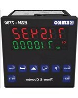
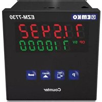
PROCESS INDICATOR UNITS
ESM-XX00

natural_image
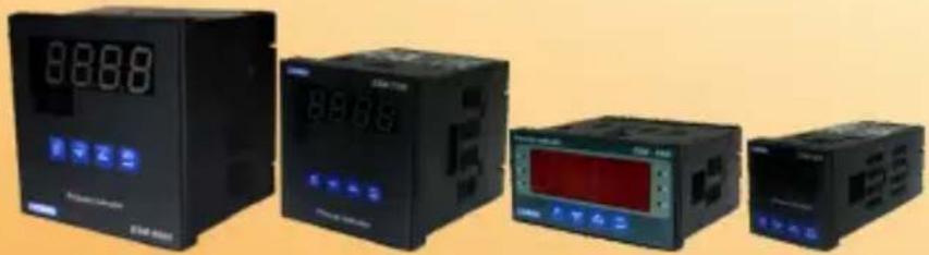
Four black industrial control units with digital displays and indicator lights, displayed against a plain yellow background (no visible text or symbols)CE ERC
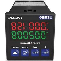
ESM-4400, ESM-7700, ESM-9900, ESM-4900
Universal Input Smart output module system Process display units
- 4 digit process (PV) display
- Universal process input (TC, RTD, mV ---, V ---, mA ---)
- Dual or multi point calibration for ____ voltage &____ current inputs
- Smart output module system
- Programmable Alarm functions
- Process control or re-transmission with 0/4...20 mA === Current output module
- RS-232 (standart) or RS-485(Optional) serial communication with Modbus RTU protocol
SPECIFICATIONS
PROCESS INPUT
Universal Input: TC, RTD, --- Voltage/Current
Thermocouple (TC): L(DIN 43710), J, K, R, S, T, B, E and N (IEC584.1)(ITS90), C (ITS90)
Thermoresistance (RTD): PT-100 (IEC751)(ITS90)
= = Input: mV, V, mA
Measurement Range : Please refer to Table-1 for selection of input type and scale
Accuracy:± 0.25% of full scale for thermocouple, thermoresistance, mV, V and mA input.
Cold Junction Compensation: Automatically ±0.1°C/1°C
Line Compensation: Maximum 10 Ohm
Sensor break protection: Upscale
Sampling Cycle:3 samples per second
Input Filter: 0.0 to 900.0 seconds
OUTPUT
Standart Relay Output: 5A@250V\~ (on resistive load)
Output Modules: User can insert 2 output module to the device.
-Relay Output Module
-SSR Output Module (Max. 26mA, Max. 22V =)
-Digital (Transistor) Output Module (Max.40 mA @18V ---)
-0/4...20 mA === Current Output Module
POWER SUPPLY
Power Supply Voltage :
100-240V ∼ 50/60 Hz (-%15;+%10) -6VA
24V ∼ 50/60 Hz (-%15 ; +%10) -6VA
(It must be determined in order.)
DISPLAY
Process Display :
ESM-4400 : 10.1 mm Red 4 digit LED Display
ESM-4900 : 20.3 mm Red 4 digit LED Display
ESM-7700 : 13.2 mm Red 4 digit LED Display
ESM-9900 : 19 mm Red 4 digit LED Display
LED Göstergeler : °C /°F / V, OP1/2/3 (Output Status) LED.
ENVIRONMENTAL RATINGS and PHYSICAL SPECIFICATIONS
Operating Temperature : 0...50°C
Humidity : 0-90%RH (non condensing)
Protection Class : IP65 at front, IP20 at rear
Mounting : Type-1 Enclosure Mounting
Installation : Fixed installation Category II
Over Voltage Category : ||
Pollution Degree : II, office or workplace, none conductive pollution
Weight:
ESM-4400: 210 gr.
ESM-4900: 260 gr.
ESM-7700: 270 gr.
ESM-9900: 360 gr.
Dimensions / Panel Cut-Out:
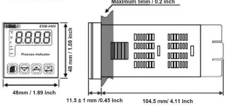
ESM-4400 : (48 x 48mm, Depth:116 mm) / (46 x 46mm)
ESM-4900 : (96 x 48mm, Depth:86.5 mm) / (92 x 46mm)
ESM-7700 : (72 x 72mm, Depth:87.5 mm) / (69 x 69mm)
ESM-9900 : (96 x 96mm, Depth:87.5 mm) / (92 x 92mm)
Minimum Distance Between Panel Cut-Out Centers:
ESM-4400:X=65mm,Y=65mm
ESM-4900 : X=129mm, Y=65mm
ESM-7700:X=97mm,Y=97mm
This symbol is used for safety warnings. User must pay attention to these warnings.

This symbol is used to determine the dangerous situations as a result of an electric shock. User must pay attention to these warnings definitely.

This symbol is used to determine the important notes about functions and usage of the device
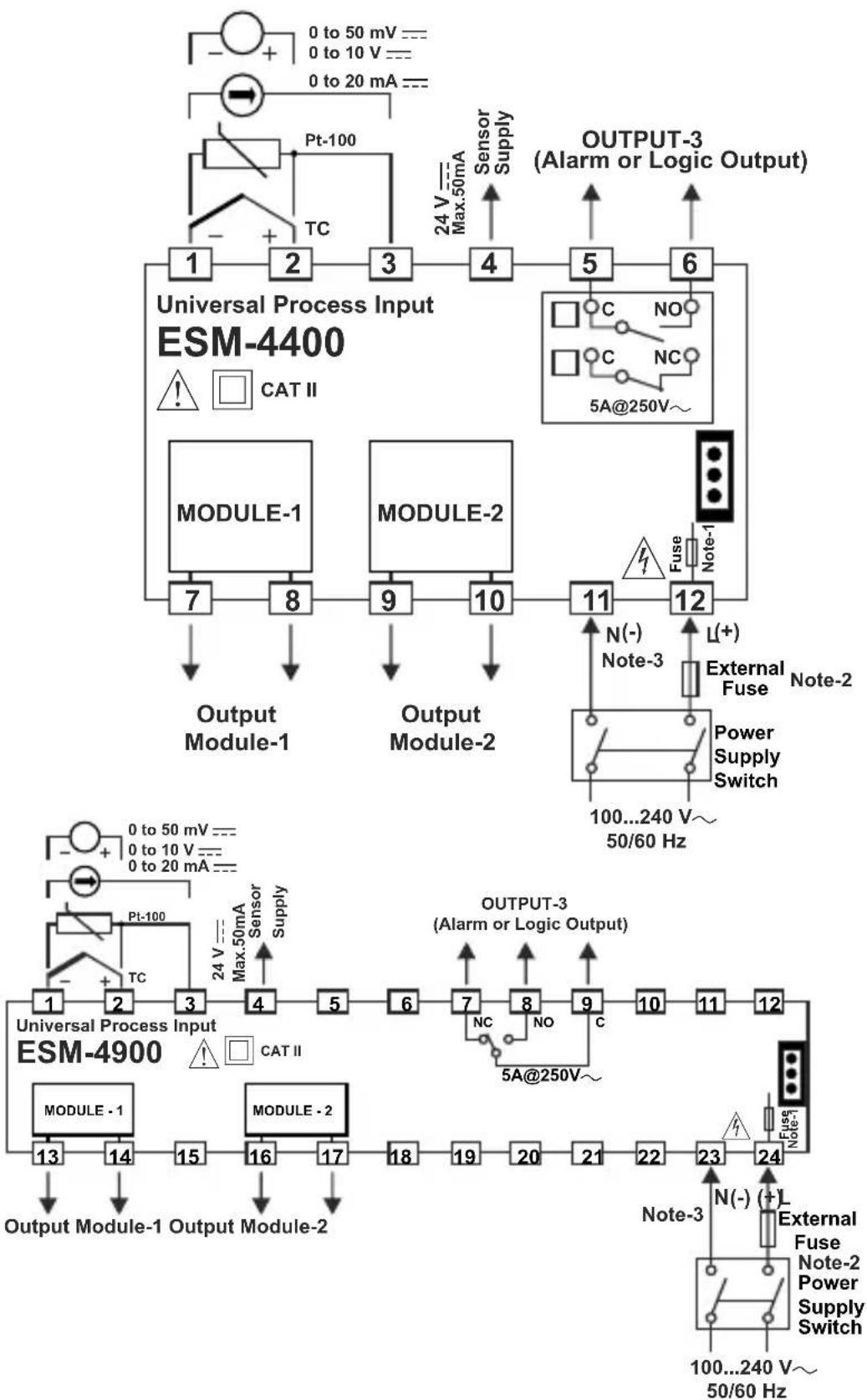
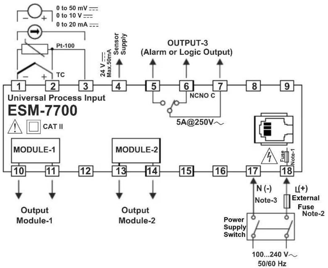
Electrical Wirings
flowchart
```mermaid
graph TD
    subgraph_ESM-4400["Universal Process Input ESM-4400"]
        A["1"] --> B["2"] --> C["3"] --> D["4"] --> E["5"] --> F["6"] --> G["OUTPUT-3 (Alarm or Logic Output)"]
        H["MODULE-1"] --> I["7"] --> J["8"] --> K["9"] --> L["10"] --> M["11"] --> N["12"]
        O["MODULE-2"] --> P["9"] --> Q["10"] --> R["11"] --> S["12"]
        T["Output Module-1"] --> U["Output Module-2"]
        V["External Fuse"] --> W["Note-1"]
        X["External Fuse"] --> Y["Note-2"]
        Z["Power Supply Switch"] --> AA["100...240 V~ 50/60 Hz"]
        AB["Noise Source"] --> AC["NO"]
        AD["Sensor Supply"] --> AE["Max.50mA"]
        AF["Sensor Supply"] --> AG["Max.50mA"]
        AH["Sensor Supply"] --> AI["Max.50mA"]
        AJ["Sensor Supply"] --> AK["Max.50mA"]
        AL["Sensor Supply"] --> AM["Max.50mA"]
        AN["Sensor Supply"] --> AO["Max.50mA"]
        AP["Sensor Supply"] --> AQ["Max.50mA"]
        AR["Sensor Supply"] --> AS["Max.50mA"]
        AT["Sensor Supply"] --> AU["Max.50mA"]
        AV["Sensor Supply"] --> AW["Max.50mA"]
        AX["Sensor Supply"] --> AY["Max.50mA"]
        AZ["Sensor Supply"] --> BA["Max.50mA"]
        BB["Sensor Supply"] --> BC["Max.50mA"]
        BD["Sensor Supply"] --> BE["Max.50mA"]
        BF["Sensor Supply"] --> BG["Max.50mA"]
        BH["Sensor Supply"] --> BI["Max.50mA"]
        BJ["Sensor Supply"] --> BK["Max.50mA"]
        BL["Sensor Supply"] --> BM["Max.50mA"]
        BN["Sensor Supply"] --> BO["Max.50mA"]
        BP["Sensor Supply"] --> BQ["Max.50mA"]
        BR["Sensor Supply"] --> BS["Max.50mA"]
        BT["Sensor Supply"] --> BU["Max.50mA"]
        BV["Sensor Supply"] --> BW["Max.50mA"]
        BX["Sensor Supply"] --> BY["Max.50mA"]
        BZ["Sensor Supply"] --> BQ
        CA["Sensor Supply"] --> CA
        CB["Sensor Supply"] --> CB
        CC["Sensor Supply"] --> CC
        DD["Sensor Supply"] --> DD
        DE["Sensor Supply"] --> DE
        FD["Sensor Supply"] --> FD
        DG["Sensor Supply"] --> DG
        DH["Fuse"] --> DH
        DI["Fuse"] --> DI
        DJ["Fuse"] --> DJ
        DK["Fuse"] --> DK
    end

    subgraph_ESM-4900["Universal Process Input ESM-4900"]
        E1["1"] --> E2["2"] --> E3["3"] --> E4["4"] --> E5["5"] --> E6["6"] --> E7["7"] --> E8["8"] --> E9["9"] --> E10["10"] --> E11["11"] --> E12["12"]
        E13["MODULE-1"] --> E14["MODULE-2"]
    end

    subgraph ESM-4900_1
        E15["TCP 24V Max.50mA Max.50mA Max.50mA Max.50mA Max.50mA Max.50mA Max.50mA Max.50mA Max.50mA Max.50mA Max.50mA Max.50mA Max.50mA Max.50mA Max.50mA Max.50mA Max.50mA Max.50mA Max.50mA Max.50mA Max.50 mA<br>        E16[Pt-100 24V Max.50mA Max.50mA Max.50mA Max.50mA Max.50mA Max.50mA Max.50mA Max.50mA Max.50mA Max.50mA Max.50mA Max.50mA Max.50mA Max.50mA Max.50mA Max.50mA Max.50mA Max.50mA Max.50mA<br>        E17[Pt-100 24V Max.50mA Max.50mA Max.50mA Max.50mA Max.50mA Max.50mA Max.50mA Max.50mA Max.50mA Max.50mA Max.50mA Max.50mA Max.50mA Max.50 mA<br>        E18[Pt-100 24V Max.50mA Max.50mA Max.50mA Max.50mA Max.50mA Max.50mA Max.50mA Max.50mA Max.50 mA<br>        E19[Pt-100 24V Max.50mA Max.50mA Max.50mA Max.50mA Max.50mA Max.50mA Max.50 mA<br>        E20[Pt-100 24V Max.50mA Max.50mA Max.50mA Max.50mA Max.50 mA<br>        E21[Pt-100 24V Max.50mA Max.50A Max 24V Max 24V Max 24V Max 24V Max 24V Max 24V Max 24V Max 24V Max 24V Max 24V Max 24V Max 24V Max 24V Max 24V Max 24V Max 24V Max 24V Max 24V Max 24V Max 24V Max 24A<br>    end<br><br>    subgraph ESM-490C<br>        E13[Pt-100 24V Max 24V Max 24V Max 24V Max 24V Max 24V Max 24V Max 24V Max 24V Max 24V Max 24V Max 24V<br>        E14[Pt-100 24V Max 24V Max 24V Max 24V Max 24V Max 24V Max 24V Max 24V Max 24V Max 24V<br>        E15[Pt-100 24V Max 24V Max 24V Max 24V Max 24V Max 24V Max 24V Max 24V<br>        E16[Pt-100 24V Max 24V Max 24V Max 24V Max 24V Max 24V Max 24V<br>        E17[Pt-100 24V Max 24V Max 24V Max 24V Max 24V Max 24V<br>        E18[Pt-100 24V Max 24V Max 24V Max 24V Max 24V<br>        E19[Pt-100 24V Max 24V Max 24V Min"]
    end

    subgraph ESM-49C
        E13["Pt-10O 24V MAX 36A Min"]
        E14["Pt-1O 24V MAX 36A Min"]
        E17["Pt-1O MAX 36A Min"]
        E18["Pt-1O MAX 36A Min"]
        E19["Pt-1O MAX 36A Min"]
    end

    subgraph ESM-49D
        E13["Pt-1O MAX 36A Min"]
        E14["Pt-1O MAX 36A Min"]
        E17["Pt-1O MAX 36A Min"]
        E18["Pt-1O MAX 36A Min"]
        E19["Pt-1O MAX 36A Min"]
    end

    subgraph ESM-49E
        E13["Pt-1O MAX 36A Min"]
        E14["Pt-1O MAX 36A Min"]
        E17["Pt-1O MAX 36A Min"]
        E18["Pt-1O MAX 36A Min"]
        E19["Pt-1O MAX 36A Min"]
    end

    subgraph ESM-49F
        E13["Pt-1O MAX 36A Min"]
        E14["Pt-1O MAX 36A Min"]
        E17["Pt-1O MAX 36A Min"]
        E18["Pt-1O MAX 36A Min"]
        E19["Pt-1O MAX 36A Min"]
    end

    subgraph ESM-49G
        E13["Pt-1O MAX 36A Min"]
        E14["Pt-1O MAX 36A Min"]
        E17["Pt-1O MAX 36A Min"]
        E18["Pt-1O MAX 36A Min"]
        E19["Pt-1O MAX 36A Min"]
    end

    subgraph ESM-49H
        E13["Pt-1O MAX 36A Min"]
        E14["Pt-1O MAX 36A Min"]
        E17["Pt-1O MAX 36A Min"]
        E18["Pt-1O MAX 36A Min"]
        E19["Pt-1O MAX 36A Min"]
    end

    subgraph ESM-49I
        E13["Pt-1O MAX 36A Min"]
        E14["Pt-1O MAX 36A Min"]
        E17["Pt-1O MAX 36A Min"]
        E18["Pt-1O MAX 36A Min"]
        E19["Pt-1O MAX 36A Min"]
    end

    subgraph ESM-49J
        E13["Pt-1O MAX 36A Min"]
        E14["Pt-1O MAX 36A Min"]
        E17["Pt-1O MAX 36A Min"]
        E18["Pt-1O MAX 36A Min"]
        E19["Pt-1O MAX 36A Min"]
    end

    subgraph ESM-49K
        E13["Pt-1O MAX 36A Min"]
        E14["Pt-1O MAX 36A Min"]
        E17["Pt-1O MAX 36A Min"]
        E18["Pt-1O MAX 36A Min"]
        E19["Pt-1O MAX 36A Min"]
    end

    subgraph ESM-49L
        E13["Pt-1O MAX 36A Min"]
        E14["Pt-1O MAX 36A Min"]
        E17["Pt-1O MAX 36A Min"]
        E18["Pt-1O MAX 36A Min"]
        E19["Pt-1O MAX 36A Min"]
    end

    subgraph ESM-49M
        E13["Pt-1O MAX 36A Min"]
        E14["Pt-1O MAX 36A Min"]
        E17["Pt-1O MAX 36A Min"]
        E18["Pt-1O MAX 36A Min"]
        E19["Pt-1O MAX 36A Min"]
    end

    subgraph ESM-49N
        E13["Pt-1O MAX 36A Min"]
        E14["Pt-1O MAX 36A Min"]
        E17["Pt-1O MAX 36A Min"]
        E18["Pt-1O MAX 36A Min"]
        E19["Pt-1O MAX 36A Min"]
    end

    subgraph ESM-49Q
        E13["Pt-1O MAX 36A Min"]
        E14["Pt-1O MAX 36A Min"]
        E17["Pt-1O MAX 36A Min"]
        E18["Pt-1O MAX 36A Min"]
        E19["Pt-1O MAX 36A Min"]
    end

    subgraph ESM-49L
        E13["PbT-PTU - PtT-U - PtT-A - PtT-B - PtT-A - PtT-B - PtT-A - PtT-B - PtT-A - PtT-B - PtT-A - PtT-B - PtT-A - PtT-B - PtT-A - PtT-B - PtT-A - PtT-B - PtT-A - PtT-B - PtT-A - PtT-B - PtT-A - PtT-B - PtT-A - PtT-B - PtT-A - PtT-B - PtT-B - PtT-A - PtT-B - PtT-A - PtT-B - PtT-A - PtT-B - PtT-A - PtT-B - PtT-A - PtT-B - PtT-A - PtT-B - PtT-A - PtT-B - PtT-A - PtT-B - PtT-A - PtT-B - PtT-A - PtT-B - PtT-A - PtT-B - PtT-A - PtT-C - PtT-U - PtT-A - PtT-B - PtT-A - PtT-B - PtT-A - PtT-B - PtT-A - PtT-B - PtT-A - PtT-B - PtT-A - PtT-B - PtT-A - PtT-B - PtT-A - PtT-B - PtT-A - PtT-B - PtT-A - PtT-B - PtT-A - PtT-B - PtT-A - PtT-C - PtT,U - PtT-A - PtT-B - PtT-A - PtT-B - PtT-A - PtT-B - PtT-A - PtT-B - PtT-A - PtT-B - PtT-A - PtT-B - PtT-A - PtT-B - PtT-A - PtT-B - PtT-A - PtT-B - PtT-A - PtT-B - PtT-A - PtT-B - PtT-A - PtT-B - PtT-EUTR / <br>            [Input: PT-TU, PT-MIN, etc., <br>            [Output: PT-TU, PT-MIN, etc., <br>            [Input: PT-MIN, etc., <br>            [Output: PT-MIN, etc., <br>            [Input: PT-MIN, etc., <br>            [Output: PT-MIN, etc., <br>            [Input: PT-MIN, etc., <br>            [Input: PT-MIN, etc., <br>            [Input: PT-MIN, etc., <br>            [Input: PT-MIN, etc., <br>            [Input: PT-MIN, etc., <br>            [Input: PT-MIN, etc., <br>            [Input: PT-MIN, etc., <br>            [Input: PT-MIN, etc., <br>            [Input: PT-MIN, etc., <br>            [Input : PT-MIN, etc., <br>            [Input: PT-MIN, etc., <br>            [Input: PT-MIN, etc., <br>            [Input: PT-MIN, etc., <br>            [Input: PT-MIN, etc., <br>            [Input: PT-MIN, etc., <br>            [Input: PT-MIN, etc., <br>            [Input: PT-MIN, etc., <br>            [Input: PT-MIN, etc., <br>            [Input: MTB, etc., <br>            [Input: PT-MIN, etc., <br>            [Input: PT-MIN, etc., <br>            [Input: PT-MIN, etc., <br>            [Input: PT-MIN, etc., <br>            [Input: PT-MIN, etc., <br>            [Input: PT-MIN, etc., <br>            [Input: PT-MIN, etc., <br>            [Input: PT-MIN, etc., <br>            [Input: PT-MIN"]
flowchart
graph TD
    A["Input: 0 to 50 mV ---"] --> B["PT-100"]
    B --> C["Sensor Supply"]
    C --> D["24 V Max.50mA"]
    D --> E["Output Module-1"]
    E --> F["Output Module-2"]
    F --> G["Output Module-3 (Alarm or Logic Output)"]
    G --> H["NCNO C"]
    H --> I["5A@250V~"]
    I --> J["Output Module-4"]
    J --> K["Module-1"]
    K --> L["CAT II"]
    M["External Fuse Note-2"] --> N["Power Supply Switch"]
    N --> O["100...240 V~ 50/60 Hz"]
    P["Fuse Note-1"] --> Q["17"]
    Q --> R["18"]
    S["Noise-3"] --> T["N (-) Note-3"]
    U["L(+) External Fuse Note-2"] --> V["Output Module-2"]
    W["External Fuse Note-1"] --> X["Output Module-1"]
    Y["External Fuse Note-3"] --> Z["Output Module-2"]

flowchart
graph TD
    A["0 to 50 mV ---"] --> B["Pt-100"]
    C["0 to 10 V ---"] --> D["Sensor Supply"]
    E["0 to 20 mA ---"] --> F["TC"]
    G["24 V --- Max.50mA"] --> H["Sensor Supply"]
    I["1"] --> J["2"]
    J --> K["3"]
    K --> L["4"]
    L --> M["5"]
    M --> N["6"]
    N --> O["7"]
    O --> P["8"]
    P --> Q["9"]
    Q --> R["10"]
    R --> S["11"]
    S --> T["12"]
    U["OUTPUT-3 (Alarm or Logic Output)"] --> V["NO"]
    V --> W["NC"]
    W --> X["C"]
    Y["5A@250V~"] --> Z["Fuse Note-1"]
    AA["MODULE - 1 MODULE - 2"] --> AB["13"]
    AB --> AC["14"]
    AC --> AD["15"]
    AD --> AE["16"]
    AE --> AF["17"]
    AF --> AG["18"]
    AG --> AH["19"]
    AH --> AI["20"]
    AI --> AJ["21"]
    AJ --> AK["22"]
    AK --> AL["23"]
    AL --> AM["24"]
    AN["N (-) Note-3"] --> AO["L(+)"]
    AO --> AP["External Fuse Note-2"]
    AQ["Power Supply Switch"] --> AR["100...240 V~ 50/60 Hz"]
Note-1 : There is an internal fusible flameproof resistor.
Note-2 : External fuse is recommended.
1100.T for power supply 240 V\~ or 24V\~
1A---T for power supply 24V ---
Note-3: “L” is (+), “N” is (-) for 24V === supply voltage
DIMENSIONS
text_image
ESM-4400 Process Indicator 8.8.8.8 48 mm / 1.89 inch 48 mm / 1.89 inch Maximum 5mm / 0.2 inch 11.5 ± 1 mm /0.45 inch 104.5 mm/ 4.11 inch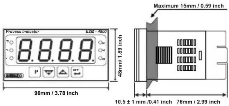
text_image
Process Indicator ESM - 4900 °C 8.8.8.8 P SET 96mm / 3.78 inch 48mm/ 1.89 inch Maximum 15mm / 0.59 inch 10.5 ± 1 mm /0.41 inch 76mm / 2.99 inch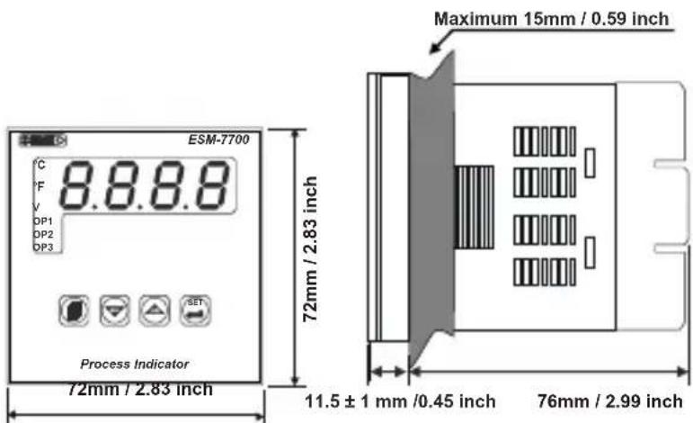
text_image
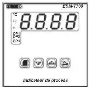
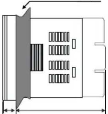
ESM-7700 °C 8.8.8.8 °F V DP1 DP2 DP3 Process Indicator 72mm / 2.83 inch 72mm / 2.83 inch Maximum 15mm / 0.59 inch 11.5 ± 1 mm / 0.45 inch 76mm / 2.99 inch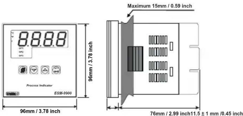
text_image
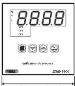
8.8.8.8 DP1 DP2 DP3 Process Indicator ESM-9900 96mm / 3.78 inch Maximum 15mm / 0.59 inch 96mm / 3.78 inch 76mm / 2.99 inch11.5 ± 1 mm /0.45 inchPANEL MOUNTING
text_image
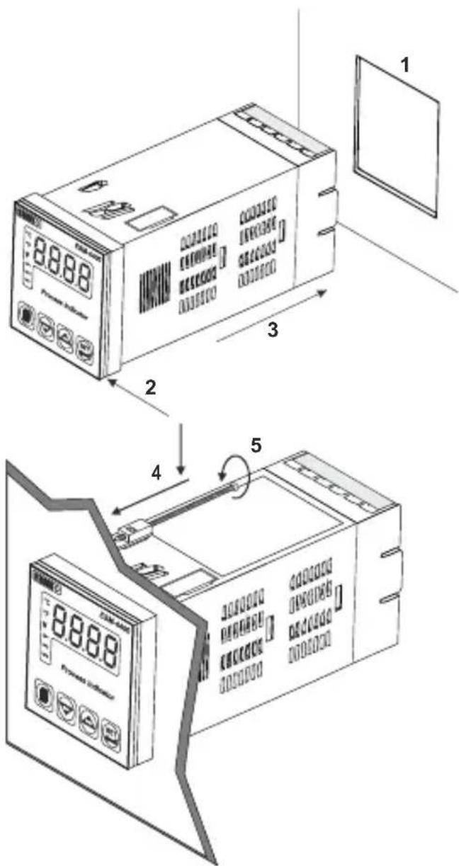
8888 Power Supply 1 2 3 4 5 8888 Power Supply1-Before mounting the device in your panel, make sure that the cut-out is of the right size. 2-Check front panel gasket position. 3-Insert the device through the cut-out. If the mounting clamps are on the unit, put out them before inserting the unit to the panel.
4-Insert the unit in the panel cut-out from the front side.
5- Insert the mounting clamps to the holes that located top and bottom sides of device and screw up the fixing screws until the unit completely immobile within the panel
Access and change Set values
Main Screen Alarm-1 Set Screen
Alarm-2 Set Screen
Main Screen

flowchart
graph LR
    A["0028"] --> B["ALr-1"]
    B --> C["OS50"]
    C --> D["0650"]
    D --> E["ALr-2"]
    E --> F["OS50"]
    F --> G["0650"]
    G --> H["ALr-3"]
    H --> I["OS50"]
    I --> J["0650"]
    J --> K["0028"]
Press SET Press Press increment Press SET Press Press increment Press SET Press Press increment Press SET
Button Increment or decrement button to Increment or decrement button to Increment or decrement button to
button to button to change save the button to button to change save the button to button to change save the
enter Alarm-1 the Alarm-1 Set Alarm-1 Set enter Alarm-2 the Alarm-2 Set Alarm-2 Set enter Alarm-3 the Alarm-3 Set Alarm-3 Set
set value. Value. value. set value. Value. value. set value. Value. value.
Note: User can exit from Set Value section without saving the values by pressing P button.
If no operation for 120 seconds, device automatically exits from Set Value section.
Easy Access diagram of Program Parameters
Main Screen Technician menu Technician password Technician password
entering screen entering screen entering screen
1 CCU 1 COC 0000
CELLA ELPS UUUU
□ □ □ □
21
Cross Set/OK Button. Press Increment button. Enter password with
Press Set/OK Button Press Increment button Enter password with to enter password to access password using increment or
to enter password to access password using increment of entering screen. entering screen decrement buttons.
Press Set/OK Button Press Increment button Enter password with Press Set/OK Button to enter password to access password using Increment or to approve password.
entering screen. entering screen decrement buttons.
Press Menu
Button.
广力云
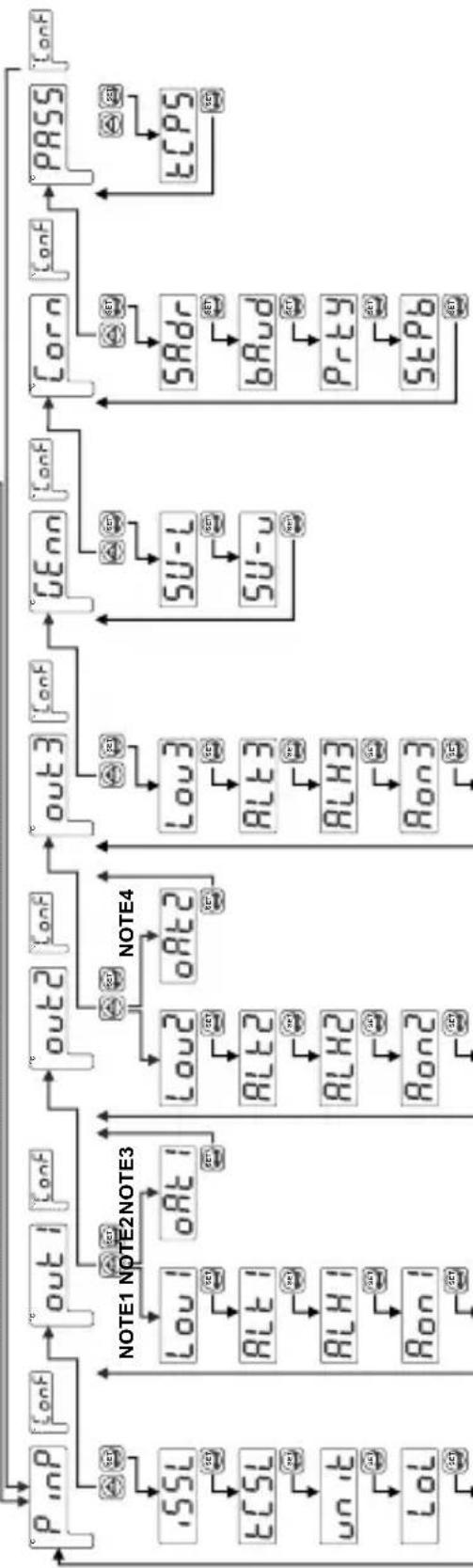
flowchart
graph TD
    A["P_inP"] --> B["out1"]
    B --> C["out2"]
    C --> D["out3"]
    D --> E["GENn"]
    E --> F["Corn"]
    F --> G["PASS"]

    subgraph Inputs
        H[".SSL"] --> I["ECSL"]
        I --> J["unit"]
        J --> K["Lol"]
    end

    subgraph Note1
        L["LOU1"] --> M["ALT1"]
        M --> N["ALH1"]
        N --> O["Ron1"]
    end

    subgraph Note2
        P["OAT1"] --> Q["ALT2"]
        Q --> R["ALH2"]
        R --> S["Ron2"]
    end

    subgraph Note3
        T["LOU2"] --> U["ALT3"]
        U --> V["ALH3"]
        V --> W["Ron3"]
    end

    subgraph Note4
        X["OAT2"] --> Y["ALT4"]
        Y --> Z["ALH4"]
        Z --> AA["Ron4"]
    end

    subgraph Outputs
        AB["LU3"] --> AC["SU-L"]
        AC --> AD["SU-u"]
        AD --> AE["SRdr"]
        AE --> AF["bAud"]
        AF --> AG["Prty"]
        AG --> AH["StPb"]
        AH --> AI["ETCPS"]
    end

    A --> H
    B --> I
    C --> M
    D --> N
    E --> U
    F --> AC
    G --> AF
    H --> I
    I --> J
    J --> K
    K --> L
    L --> M
    M --> N
    N --> O
    O --> W
    W --> V
    V --> X
    X --> U
    U --> AC
    AC --> AD
    AD --> AE
    AE --> AF
    AF --> AG
    AG --> AH
    AH --> AI

    style Inputs fill:#f9f,stroke:#333
    style Note1 fill:#ccf,stroke:#333
    style Note2 fill:#ccf,stroke:#333
    style Note3 fill:#ccf,stroke:#333
    style Note4 fill:#ccf,stroke:#333
NOTE1: If there is EMO-X00, EMO-X10, EMO-X20 output module in MODULE-1 socket, these parameters are shown.
NOTE2: If there is EMO-X00, EMO-X10, EMO-X20 output module in MODULE-2 socket, these
parameters are shown.
NOTE3: If there is EMO-X30 module in MODULE-1 socket, this parameter is shown.
NOTE4: If there is EMO-X30 module in MODULE-2 socket, this parameter is shown.
ENGLISH
PinP ConF: Process Input Type and Relevant Parameters
,55L Process Input Type
0000 TC input type selection
000 RTD input type selection
0002 ---Voltage / Current input type selection.
ECSL TC Input Selection
This parameter is active if TC input type is selected.
0000 L (-100°C;850°C) or (-148°F;1562°F)
0001 L (-100.0°C;850.0°C) or (-148.0°F;999.9°F)
0002 J (-200°C;900°C) or (-328°F;1652°F)
0003 J (-199.9°C; 900.0°C) or (-199.9°F; 999.9°F)
0004 K (-200°C;1300°C) or (-328°F;2372°F)
0005 K (-199.9°C; 999.9°C) or (-199.9°F; 999.9°F)
0006 R (0°C;1700°C) or (32°F;3092°F)
0007 R (0.0°C;999.9°C) or (32.0°F;999.9°F)
0008 S (0°C;1700°C) or (32°F;3092°F)
0009 S (0.0°C;999.9°C) or (32.0°F;999.9°F)
00 10 T (-200°C;400°C) or (-328°F;752°F)
0011 T (-199.9°C;400.0°C) or (-199.9°F;752.0°F)
00:12 B (44°C;1800°C) or (111°F;3272°F)
0013 B (44.0°C;999.9°C) or (111.0°F; 999.9°F)
0014 E (-150°C;700°C) or (-238°F;1292°F)
0015 E (-150.0°C;700.0°C) or (-199.9°F;999.9°F)
00:16 N (-200°C; 1300°C) or (-328°F; 2372°F)
0017 N (-199.9°C;999.9°C) or (-199.9°F;999.9°F)
00:18 C (0°C;2300°C) or (32°F;3261°F)
00 19 C (0.0°C;999.9°C) or (32.0°F;999.9°F)
rtd5 RTD Input Selection
This parameter is active if RTD input is selected.
0000 PT-100 (-200°C; 650°C) or (-328°F; 1202°F)
000 PT-100 (-199.9°C ; 650.0°C ) or (-199.9°F ;999.9°F)
uRSL ——voltage / Current Input Selection
This parameter is active if —Voltage / Current is selected.
0000 0...50mV = (-1999; 9999)
000: 0...5V = (-1999; 9999)
0002 0...10V = (-1999; 9999)
0003 0...20mA = (-1999; 9999)
0004 4...20mA = (-1999; 9999)

Display Point Position
This parameter is active if oltage/Current input is selected. V

No point

Between first and second digits "0.0"

Between second and third digits "0.00"

Between third and fourth digits "0.000"

Display Value Adjustment Type
This parameter is active if oltage/Current input is selected. V

Fixed dual point display adjustment. Display adjustment low point value is fixed to -1999, display adjustment high point value is fixed to 9999.

User can do dual point display adjustment with tPoL and tPoH.

User can do defined 16 display adjustment points.

Low Point Display adjustment (-1999, 9999)Unit
This parameter is active if oltage/Current input is selected. V

High Point Display adjustment (-1999, 9999)Unit
This parameter is active if voltage/Current input is selected.——V

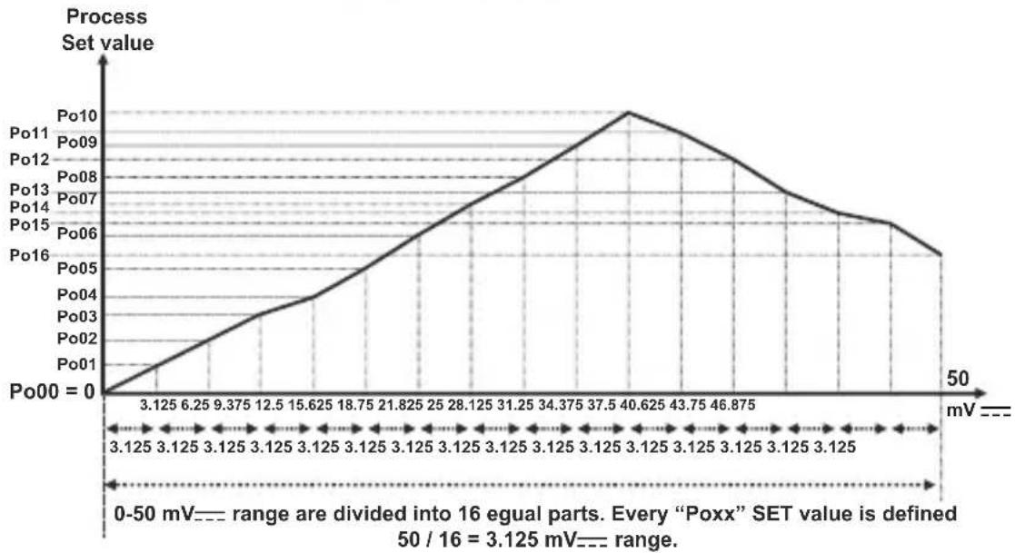
Display adjustment points (-1999, 9999)Unit
This parameter is active if voltage/Current input is selected. In multi point display adjustment operation, defined scale is divided into 16 adjustment points.

For example: UASL is 0000 (0-50 mV)
line
| Point | Process Set value | |-------|-------------------| | Po00 | 0 | | Po01 | 3.125 | | Po02 | 6.25 | | Po03 | 9.375 | | Po04 | 12.5 | | Po05 | 15.625 | | Po06 | 18.75 | | Po07 | 21.825 | | Po08 | 24 | | Po09 | 26.125 | | Po10 | 28.125 | | Po11 | 31.25 | | Po12 | 34.375 | | Po13 | 37.5 | | Po14 | 40.625 | | Po15 | 43.75 | | Po16 | 46.875 |
Coefficient value (1.000, 9.999)
Process value is multiplied with this value.
---VThis parameter is active if oltage/Current input is

Unit selection

Unit is °C

Unit is °F

Unit is Voltage. This selection is active if ===Voltage/Current input is selected

No unit. This selection is active if voltage / current input is selected

Operating Scale Minimum Value (Scale Low Point, Scale High Point)Unit
Used for Proportional band calculation and display blink.

Operating Scale Maximum Value (Scale Low Point, Scale High Point)Unit
Used for Proportional band calculation and display blink.

Display offset for process value (Scale -10%, Scale +10%)Unit
This parameter value is added to the process value.

Filter Time (0.0, 900.0)Second
Defines filter time for display value.

Cold Junction Compensation
This parameter is active if process input is selected TC input.

Cold junction compensation is active.

Cold junction compensation is not active.
Scale: The difference, between high point and low point of the process input type. Example: If tCSL = 2 (low point is -200, high point is 900), then scale is 1100. If input type is Voltage/Current, then the scale is difference between tPoH and tPoL parameters.
out1 ConF: MODULE-1 parameters

If there is EMO-X00 (Relay Output), EMO-X10 (SSR driver) and EMO-X20 (Digital Output) module in MODULE-1 socket, then the following parameters is active.

MODULE-1 output module Logic output function
0000
Alarm output
0001
Sensor break alarm output
0002
Output is active when the process value is out of the band which is defined with minimum value of operating scale and maximum value of operating scale

Alarm-1 Type
MODULE-1 alarm type. This parameter is active, if the Logic-1 output function is Alarm output.
0000
Process high alarm
0001
Process low alarm

Alarm-1 hysteresis value (0% of scale, 50% of scale)Unit
This parameter is active, if the Logic-1 output function is Alarm output.

Alarm-1 On delay time (0, 9999)Second
This parameter is active, if the Logic-1 output function is Alarm output.

Alarm-1 Off Delay Time (0, 9998)Second
When the value is greater than 9998, LCH is seen on the screen. It means alarm latching output is selected. This parameter is active if logic-1 output function of Alarm-1 Output is alarm output.
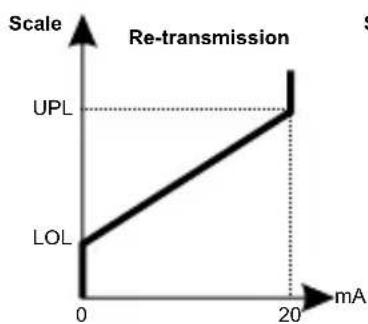
out1 ConF: MODULE-1 parameters

If there is EMO-X30 (0/4...20 mA == Current output module in MODULE-1 socket, then the following parameter is active.

MODULE-1 analogue output module configuration
0000 0...20mA--- output
0001 4...20mA--- output
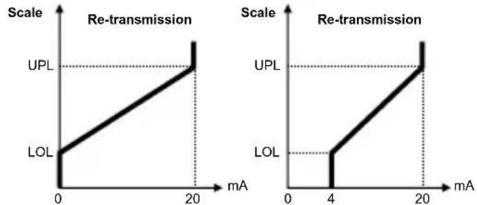
line
Re-transmission | Scale | Re-transmission (mA) | UPL (mA) | LOL (mA) | |---|---|---|---| | 0 | 0 | UPL | LOL | | 20 | 20 | UPL | LOL | | 4 | 4 | UPL | LOL | | 20 | 20 | UPL | LOL |out2 ConF: MODULE-2 parameters

If there is EMO-X00 (Relay Output), EMO-X10 (SSR driver) and EMO-X20 (Digital Output) module in MODULE-2 socket, then the following parameters is active.

MODULE-2 output module Logic output function
0000
Alarm output
0001
Sensor break alarm output
0002
Output is active when the process value is out of the band which is defined with minimum value of operating scale and maximum value of operating scale

Alarm-2 Type
MODULE-2 alarm type. This parameter is active, if the Logic-2 output function is Alarm output.
0000
Process high alarm
0001
Process low alarm

Alarm-2 hysteresis value (0% of scale, 50% of scale) Unit
This parameter is active, if the Logic-2 output function is Alarm output.

Alarm-2 On delay time (0, 9999)Second
This parameter is active, if the Logic-2 output function is Alarm output.

Alarm-2 Off Delay Time (0, 9998)Second
When the value is greater than 9998, LCH is seen on the screen. It means alarm latching output is selected. This parameter is active if logic-2 output function of Alarm-2 Output is alarm output.
out2 ConF: MODULE-2 parameters

If there is EMO-X30 (0/4...20 mA == Current output module in MODULE-2 socket, then the following parameter is active.

MODULE-2 analogue output module configuration
0000 0...20mA--- output
0001 4...20mA--- output
line
| Scale | Re-transmission | | :--- | :--- | | 0 | UPL | | 20 | UPL |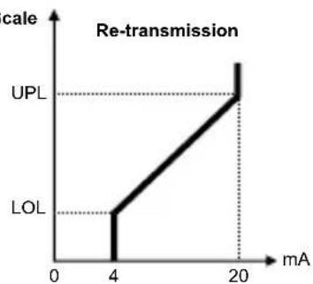
line
| mA | Re-transmission | |----|-----------------| | 4 | UPL | | 20 | LOL |out3 ConF: MODULE-3 parameters

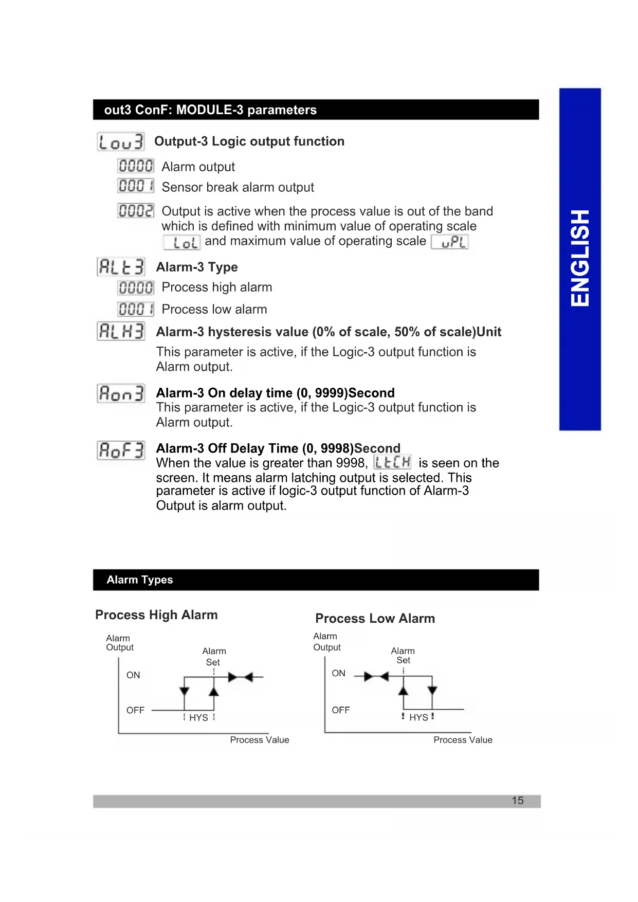
Output-3 Logic output function
0000
Alarm output
0001
Sensor break alarm output
0002
Output is active when the process value is out of the band which is defined with minimum value of operating scale and maximum value of operating scale

Alarm-3 Type
0000
Process high alarm
0001
Process low alarm

Alarm-3 hysteresis value (0% of scale, 50% of scale)Unit
This parameter is active, if the Logic-3 output function is Alarm output.

Alarm-3 On delay time (0, 9999)Second
This parameter is active, if the Logic-3 output function is Alarm output.

Alarm-3 Off Delay Time (0, 9998) Second
When the value is greater than 9998, LCH is seen on the screen. It means alarm latching output is selected. This parameter is active if logic-3 output function of Alarm-3 Output is alarm output.
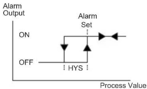
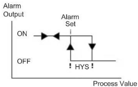
Alarm Types
Process High Alarm
flowchart
graph TD
    A["ON"] --> B["HYS"]
    B --> C["Set"]
    C --> D["OFF"]
    style A fill:#f9f,stroke:#333
    style B fill:#ccf,stroke:#333
    style C fill:#cfc,stroke:#333
    style D fill:#fcc,stroke:#333
Process Low Alarm
flowchart
graph TD
    A["ON"] --> B["Alarm Set"]
    B --> C["HYS"]
    D["OFF"] --> C
    style A fill:#f9f,stroke:#333
    style B fill:#ccf,stroke:#333
    style C fill:#cfc,stroke:#333
Alarm Types
Process High Alarm
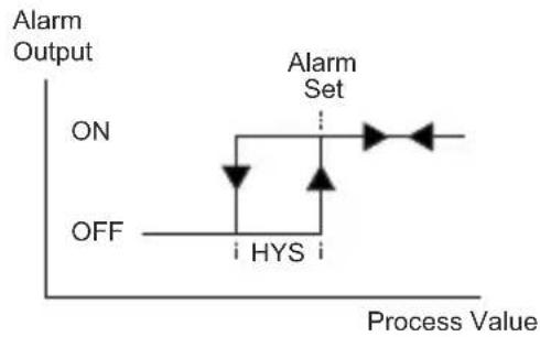
flowchart
graph TD
    A["ON"] --> B["HYS"]
    B --> C["Alarm Set"]
    C --> D["Process Value"]
    style A fill:#f9f,stroke:#333
    style C fill:#ccf,stroke:#333
    style D fill:#cfc,stroke:#333
Process Low Alarm
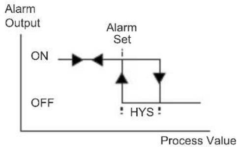
flowchart
graph TD
    A["ON"] --> B["Alarm Set"]
    B --> C["HYS"]
    C --> D["Process Value"]
    style A fill:#f9f,stroke:#333
    style B fill:#ccf,stroke:#333
    style C fill:#cfc,stroke:#333
    style D fill:#fcc,stroke:#333
Gen ConF: General Parameters

Alarm Set value Low limit ( Lol, 5U-u)Unit

Alarm Set ( , )Ubitvalue High limit
Com ConF: Serial Communication Configuration Parameters

Communication Accessing Address (1,247)
Communication accessing address of device.
Communication accessing address can be adjusted from 1 to 247.

Communication Baud Rate

1200 Baud Rate.

2400 Baud Rate.
4800 Baud Rate
9600 Baud Rate
19200 Baud Rate

Parity Selection for Communication
No parity.
Odd parity.
Even parity.

Stop Bit Selection for Communication
1 stop bit
2 stop bit
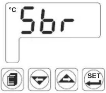
ESM-XX00 Process Control Unit Error Messages
text_image
°C 56r SET1 - Sensor failure in analogue inputs. Sensor connection is wrong or there is no sensor connection.
text_image
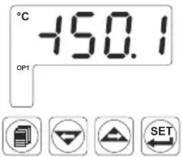
°C -150.1 OP1 SET2- If top display blinks : If analogue input value is less than minimum value of operating scale [Lol] top display starts to blink.
text_image
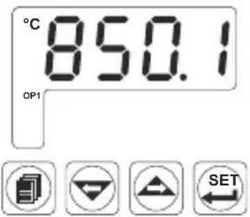
°C 850.1 OP1 SET3- If top display blinks : If analogue input value is greater than maximum value of operating scale top display starts to blink.
text_image
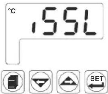
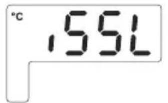
°C 155L SET
text_image
°C SET4- If technician password is different from "0" and user accesses to the parameter by Set button without entering the technician password and wants to change a parameter, the warning message is shown on the display as shown on the right. Device does not allow to do any changes without entering the password correctly.
Installation

Before beginning installation of this product, please read the instruction manual and warnings below carefully.
In package,
- One piece unit
- Two pieces mounting clamp
- One piece instruction manual
A visual inspection of this product for possible damage occurred during shipment is recommended before installation. It is your responsibility to ensure that qualified mechanical and electrical technicians install this product.
If there is danger of serious accident resulting from a failure or defect in this unit, power off the system and separate the electrical connection of the device from the system.
The unit is normally supplied without a power switch or a fuse. Use power switch and fuse as required.
Be sure to use the rated power supply voltage to protect the unit against damage and to prevent failure.
Keep the power off until all of the wiring is completed so that electric shock and trouble with the unit can be prevented.
Never attempt to disassemble, modify or repair this unit. Tampering with the unit may results in malfunction, electric shock or fire.
Do not use the unit in combustible or explosive gaseous atmospheres.
During the equipment is putted in hole on the metal panel while mechanical installation some metal burrs can cause injury on hands, you must be careful.
Montage of the product on a system must be done with it's mounting clamp. Do not do the montage of the device with inappropriate mounting clamp. Be sure that device will not fall while doing the montage.
It is your responsibility if this equipment is used in a manner not specified in this instruction manual.
Warranty
EMKO Elektronik warrants that the equipment delivered is free from defects in material and workmanship. This warranty is provided for a period of two years. The warranty period starts from the delivery date. This warranty is in force if duty and responsibilities which are determined in warranty document and instruction manual performs by the customer completely.
Maintenance
Repairs should only be performed by trained and specialized personnel. Cut power to the device before accessing internal parts. Do not clean the case with hydrocarbon-based solvents (Petrol, Trichlorethylene etc.). Use of these solvents can reduce the mechanical reliability of the device. Use a cloth dampened in ethyl alcohol or water to clean the external plastic case.
Other Informations
Manufacturer Information:
Emko Elektronik Sanayi ve Ticaret A.Ş. Demirtaş Organize Sanayi Bölgesi Karanfil Sk. No:6 16369 BURSA /TURKEY
Phone : +90 224 261 1900 Fax : +90 224 261 1912
Repair and Maintenance Service Information:
Emko Elektronik Sanayi ve Ticaret A.Ş. Demirtaş Organize Sanayi Bölgesi Karanfil Sk. No:6 16369 BURSA /TURKEY
Phone : +90 224 261 1900 Fax : +90 224 261 1912
Ordering Information
| ESM-4400 (48x48 DIN 1/16) |
| ESM-4900 (96x48 DIN 1/8) |
| ESM-7700 (72x72 DIN Size) |
| ESM-9900 (96x96 DIN 1/4) |
| A | Supply Voltage |
| 1 | 100-240V ~ (-%15;+%10) 50/60Hz |
| 2 | 24V ~ (-%15;+%10) 50/60Hz 24V --- (-%15;+%10) |
| 9 | Customer (Maximum 240V ~ (-%15;+%10))50/60Hz |
| Input type ScaleBC | ||
| 20 | Configurable(Table-1) Table-1 |
| Serial CommunicationD | Product Code | |
| 0 | None | |
| 1 | RS-232 | EMC-400,EMC-700,EMC-900 |
| 2 | RS-485 | EMC-410,EMC-710,EMC-910 |
| E | Output-3 |
| 1 | Relay Output(5A@250V~ on resistive Load) |
| FG | Module-1 | Module Codes |
| 00 | None | |
| 01 | Relay Output Module | EMO-400,EMO-700,EMO-900 |
| 02 | SSR driver Output Module(Maximum 26mA, 22V =--) | EMO-410,EMO-710,EMO-910 |
| 03 | Digital (Transistor) Output Module(Maximum 40mA@18V =--) | EMO-420,EMO-720,EMO-920 |
| 04 | Current Output Module(0/4...20 mA =--- veya 0...10V =--) | EMO-430,EMO-730,EMO-930 |
| HI | Module-2 | Module Codes |
| 00 | None | |
| 01 | Relay Output Module | EMO-400,EMO-700,EMO-900 |
| 02 | SSR driver Output Module(Maximum 26mA, 22V ==) | EMO-410,EMO-710,EMO-910 |
| 03 | Digital (Transistor) Output Module(Maximum 40mA@18V ==) | EMO-420,EMO-720,EMO-920 |
| 04 | Current Output Module(0/4...20 mA == veya 0...10V ==) | EMO-430,EMO-730,EMO-930 |
Table-1
| BC | Input Type(TC) | Scale(°C) | Scale(°F) |
| 21 | L ,Fe Const DIN43710 | -100°C,850°C | -148°F ,1562°F |
| 22 | L ,Fe Const DIN43710 | -100.0°C,850.0°C | -148.0°F,999.9°F |
| 23 | J ,Fe CuNi IEC584.1(ITS90) | -200°C,900°C | -328°F,1652°F |
| 24 | J ,Fe CuNi IEC584.1(ITS90) | -199.9°C,900.0°C | -199.9°F,999.9°F |
| 25 | K ,NiCr Ni IEC584.1(ITS90) | -200°C,1300°C | -328°F,2372°F |
| 26 | K ,NiCr Ni IEC584.1(ITS90) | -199.9°C,999.9°C | -199.9°F,999.9°F |
| 27 | R ,Pt13%Rh Pt IEC584.1(ITS90) | 0°C,1700°C | 32°F,3092°F |
| 28 | S ,Pt10%Rh Pt IEC584.1(ITS90) | 0°C,1700°C | 32°F,3092°F |
| 29 | T ,Cu CuNi IEC584.1(ITS90) | -200°C,400°C | -328°F,752°F |
| 30 | T ,Cu CuNi IEC584.1(ITS90) | -199.9°C,400.0°C | -199.9°F,752.0°F |
| 31 | B ,Pt30%Rh Pt6%Rh IEC584.1(ITS90) | 44°C,1800°C | 111°F,3272°F |
| 32 | B ,Pt30%Rh Pt6%Rh IEC584.1(ITS90) | 44.0°C,999.9°C | 111.0°F,999.9°F |
| 33 | E ,NiCr CuNi IEC584.1(ITS90) | -150°C,700°C | -238°F,1292°F |
| 34 | E ,NiCr CuNi IEC584.1(ITS90) | -150.0°C,700.0°C | -199.9°F,999.9°F |
| 35 | N ,Nicrosil Nisil IEC584.1(ITS90) | -200°C,1300°C | -328°F,2372°F |
| 36 | N ,Nicrosil Nisil IEC584.1(ITS90) | -199.9°C,999.9°C | -199.9°F,999.9°F |
| 37 | C , (ITS90) | 0°C,2300°C | 32°F,3261°F |
| 38 | C , (ITS90) | 0.0°C,999.9°C | 32.0°F,999.9°F |
| BC | Input Type(RTD) | Scale(°C) | Scale(°F) |
| 39 | PT 100 , IEC751(ITS90) | -200°C,650°C | -328°F,1202°F |
| 40 | PT 100 , IEC751(ITS90) | -199.9°C,650.0°C | -199.9°F,999.9°F |
| BC | Input Type( --- Voltage and Current) | Scale |
| 41 | 0...50 mV --- | -1999,9999 |
| 42 | 0...5 V --- | -1999,9999 |
| 43 | 0...10 V --- | -1999,9999 |
| 44 | 0...20 mA --- | -1999,9999 |
| 45 | 4...20 mA --- | -1999,9999 |


Thank you very much for your preference to use Emko Elektronik products, please visit our web page to download detailed user manual.
www.emkoelektronik.com.tr
ESM-XX00 PROZESSANZEIGE
natural_image
Four black industrial control unit units with digital displays and indicator lights, displayed against a plain yellow background (no visible text or symbols)CE ERC
ESM-4400, ESM-7700, ESM-9900, ESM-4900
0...50mV = (-1999; 9999)
0...5V = (-1999; 9999)
2 0...10V --- (-1999; 9999)
3 0...20mA = (-1999; 9999)
4...20mA = (-1999; 9999)

line
| Voltage Level | Power | | :--- | :--- | | Po00 = 0 | 0 | | Po01 | 3.125 | | Po02 | 3.125 | | Po03 | 3.125 | | Po04 | 3.125 | | Po05 | 3.125 | | Po06 | 3.125 | | Po07 | 3.125 | | Po08 | 3.125 | | Po09 | 3.125 | | Po10 | 3.125 | | Po11 | 3.125 | | Po12 | 3.125 | | Po13 | 3.125 | | Po14 | 3.125 | | Po15 | 3.125 | | Po16 | 3.125 | The chart displays a single line representing a power level across the voltage range from 0 to 50 mV, with a dashed vertical line at 31.25 mV marking the peak power level of Po07. Below it, a dotted arrow indicates the region defined by the 0-50mV threshold for Teile geteilt.Jeder "Poxx" SET-Wert 50/16 is noted as "wird" in the region defined by Abstand definiert.
Multiplikationsfaktor (1.000, 9.999)
text_image
°C -150.1 OP1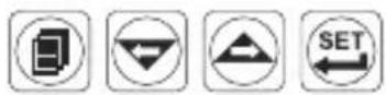
text_image
°C 850.1 CP1
text_image
°C 155L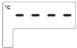
natural_image
Simple L-shaped diagram with four horizontal dashed lines and a label '°C' on the top (no other text or symbols)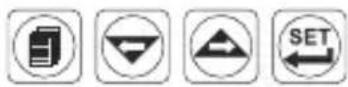
natural_image
Four black electronic devices with digital displays and control buttons, displayed against a plain yellow background (no visible text or symbols on devices)CE ERC
ESM-4400, ESM-7700, ESM-9900, ESM-4900
natural_image
Technical line drawing of a rectangular device with internal compartments and a side panel, showing dimension lines (no text or symbols)natural_image
Technical line drawing of a mechanical component with internal slots and dimension lines (no text or symbols)10,5 ± 1 mm / 0,41 pouce 76 mm / 2,99 pouces
text_image
ESM-7700 °C 8.8.8.8 °F V OP1 OP2 OP3 Indicateur de process72 mm / 2,83 pouces
72 mm / 2,83 pouces
Maximum 15 mm / 0,59 pouce
natural_image
Pure technical diagram of a mechanical or electrical component with no text, numbers, or symbols11,5 ± 1 mm / 0,45 pouces 76 mm / 2,99 pouces
text_image
°C 8.8.8.8 OP1 OP2 OP3 Indicateur de process ESM-990096 mm / 3,78 pouces
96 mm / 3,78 pouces
Maximum 15 mm / 0,59 pouce
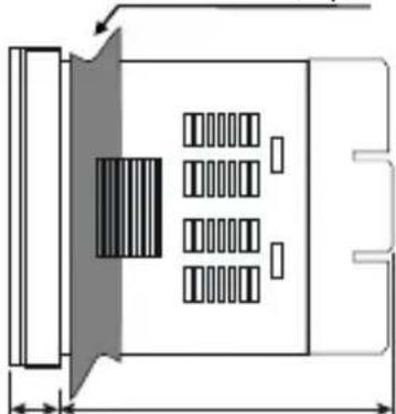
natural_image
Technical line drawing of a mechanical or electronic component with internal compartments and a shaded central section (no text or symbols)0003 0...20 mA --- (-1999; 9999)
0004 4...20 mA = (-1999; 9999)

Affichage position de point
line
| Point | Value | | :--- | :--- | | Po00 = 0 | 0 | | Po01 | 0 | | Po02 | 0 | | Po03 | 0 | | Po04 | 0 | | Po05 | 0 | | Po06 | 0 | | Po07 | 0 | | Po08 | 0 | | Po09 | 0 | | Po10 | 0 | | Po11 | 0 | | Po12 | 0 | | Po13 | 0 | | Po14 | 0 | | Po15 | 0 | | Po16 | 0 | The chart displays a single line plot representing the value of the consigne du process as a function of voltage in mV. The annotation below it indicates that La gamme is 0-50 mV, and the text below it shows that the game is divided into 16 parties égales. Chaque valeur de consigne (SET) is defined as 50/16 = gamme 3,125 mV. The x-axis is labeled 'mV' with values ranging from 3.125 to 46.875 mV. The y-axis is labeled 'Valeur de consigne du process'.
line
| mA | Échelle | | --- | ------- | | 0 | 0 | | 4 | 0 | | 20 | UPL |text_image
°C -150.1 OP1
text_image
°C 155L SET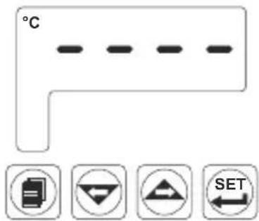
text_image
°C SET| A | BC | D | E | FG | HI / | U | V | W | Z/ | ||||
| 1 | / | / | 0 | 0 | 0 | 0 |
| A | Tension d'alimentation |
| 1 | 100-240 V ~ (-%15;+%10) 50/60 Hz |
| 2 | 24 V ~ (-%15;+%10) 50/60 Hz 24 V = -(-%15;+%10) |
| 9 | Client (Maximum 240 V ~ (-%15;+%10)) 50/60 Hz |
natural_image
Four black industrial control unit units with digital displays and buttons, displayed against a plain yellow background (no visible text or symbols)CE EAC
ESM-4400, ESM-7700, ESM-9900, ESM-4900
ESM-7700: X = 97 mm, Y = 97 mm
ESM-9900: X = 129 mm, Y = 129 mm

line
| mA | Escala | | --- | ------ | | 4 | UPL | | 20 | |text_image
°C 56r SETtext_image
°C -150.1 OP1 SETtext_image
°C 850.1 OP1 SETtext_image
°C 155L SET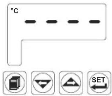
text_image
°C SET| A | BC | D | E | FG | HI / | U | V | W | Z/ | ||||
| 1 | / | / | 0 | 0 | 0 | 0 |
| A | Tensión de alimentación |
| 1 | 100-240 V ~ (-%15; +%10) 50/60 Hz |
| 2 | 24 V ~ (-%15; +%10) 50/60 Hz 24 V = -(-%15; +%10) |
| 9 | Cliente (Máximo 240 V ~ (-%15; +%10)) 50/60 Hz |
| Tipo de Entrada EscalaBC | ||
| 20 | Configurable (Tabla-1) | Tabla-1 |