
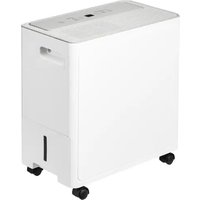
MDDN10DEN7 - Dehumidifier COMFEE - Free user manual and instructions
Find the device manual for free MDDN10DEN7 COMFEE in PDF.
| Product Type | Dehumidifier |
| Brand | Comfee |
| Model | MDDN10DEN7 |
| Humidity Setting | From 35% to 85% in 5% steps |
| Continuous Mode | Yes, for maximum dehumidification |
| Display | LED, displays set and ambient humidity |
| Auto Shut-Off | Yes, when the bucket is full or removed |
| Auto Defrost | Yes, the compressor stops and the fan continues |
| Auto Restart | Yes, after a power outage |
| Continuous Drainage | Possible via drain hose (not included) |
| Bucket Capacity | Approximately 2 liters (estimation) |
| Operating Temperature | 5°C to 32°C |
| Operating Humidity | 30% to 80% RH |
| Refrigerant | R290 or R32 (flammable) |
| Filter Maintenance | Clean every 2 weeks with soapy water |
| Bucket Cleaning | Every few weeks with mild detergent |
| Available Spare Parts | Air filter, water bucket, drain hose |
| Usage | Residential indoor only |
| Minimum Distance to Walls | 20 cm on each side |
| Weight | Not specified in the manual |
| Dimensions | Not specified in the manual |
Frequently Asked Questions - MDDN10DEN7 COMFEE
User questions about MDDN10DEN7 COMFEE
0 question about this device. Answer the ones you know or ask your own.
Ask a new question about this device
Download the instructions for your Dehumidifier in PDF format for free! Find your manual MDDN10DEN7 - COMFEE and take your electronic device back in hand. On this page are published all the documents necessary for the use of your device. MDDN10DEN7 by COMFEE.
USER MANUAL MDDN10DEN7 COMFEE
natural_image
Line drawing of a portable air purifier device with control panel and ventilation grille (no text or symbols)natural_image
Symbol of a trash bin crossed with no text or numbers, representing waste sorting or disposal (no text present)natural_image
Simple line drawing of an open book with no text or symbols visible
Abb. 3
natural_image
Diagram of a mechanical device with an open lid and internal components, showing an upward arrow (no text or symbols present)Abb.5
natural_image
Diagram of a mechanical device with directional arrows indicating movement or force (no text or symbols present)Abb.6
natural_image
Line drawing of a portable air conditioner unit with ventilation grille and attached sensor (no text or symbols)Deckel abschneiden
Abb. 7
natural_image
Diagram of a device emitting smoke or heat, showing airflow direction with arrows (no text or symbols)Abb. 8
natural_image
Diagram of a device with a grid pattern and directional arrow (no text or symbols)Abb. 10
natural_image
Line drawing of a portable air purifier device with control panel and wheels (no text or symbols)natural_image
Symbol of a trash bin crossed with no visible text or labelsMISURE DI SICUREZZA
Avvertenza....2
Precauzioni 2
Nota sui gas fluorurati
natural_image
Warning symbol of a flame inside a triangle (no text or numbers)natural_image
Simple line drawing of an open book with no text or symbols visiblenatural_image
Diagram of a device with internal components and directional arrows indicating movement (no text or symbols)Fig. 5
natural_image
Technical line drawing of a mechanical device with internal components and an upward arrow indicating motion (no text or symbols)Fig. 6
- Versare l'acqua.
NOTA:
natural_image
Diagram of a portable electronic device with ventilation grille and airflow direction arrow (no text or symbols)Fig. 10
Attenzione:
natural_image
Line drawing of a portable air purifier device with control panel and wheels (no text or symbols)natural_image
Symbol of a trash bin crossed with no visible text or labelsPRÏCAUTIONS DE SÏCURITI
Avertissement 2
Attention 2
natural_image
Warning symbol of a flame inside a triangle (no text or numbers)natural_image
Simple line drawing of an open book with no text or symbols visibleFront
Figure 2
Figure 3
natural_image
Diagram of a device with internal components and directional arrows indicating movement (no text or symbols)Figure 5
natural_image
Technical line drawing of a mechanical device with internal components and an upward arrow indicating motion (no text or symbols)Figure 6
- Versez l'eau.
Figure 8
natural_image
Technical line drawing of a portable water heater with internal grating and handle (no text or symbols)natural_image
Diagram of a portable electronic device with ventilation grilles and airflow direction arrow (no text or symbols)Figure 10
ATTENTION:
natural_image
Line drawing of a portable air purifier device with control panel and wheels (no text or symbols)Before operating this product, please read the instructions carefully and save this manual for future use.
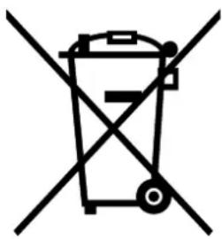
When using this dehumidifier in the European countries, the following information must be followed:
DISPOSAL: Do not dispose this product as unsorted municipal waste. Collection of such waste separately for special treatment is necessary.
It is prohibited to dispose of this appliance in domestic household waste.
For disposal, there are several possibilities:
A) The municipality has established collection systems, where electronic waste can be disposed of at least free of charge to the user.
B) When buying a new product, the retailer will take back the old product at least free of charge.
C) The manufacture will take back the old appliance for disposal at least free of charge to the user.
D) As old products contain valuable resources, they can be sold to scrap metal dealers.
Wild disposal of waste in forests and landscapes endangers your health when hazardous substances leak into the ground-water and find their way into the food chain.
natural_image
Symbol of a trash bin crossed out by two diagonal lines (no text or numbers present)
CONTENTS
SAFETY PRECAUTIONS
Warning 2
Caution 2
Electrical information 4
WARNINGS (for using R290/R32 refrigerant only) 5
CONTROL PADS ON THE DEHUMIDIFIER
Control pads....11
Other features....12
IDENTIFICATION OF PARTS
Identification of parts 12
Positioning the unit 13
OPERATING THE UNIT
When using the unit 13
Removing the collected water 14
CARE AND MAINTENANCE
Care and cleaning of the dehumidifier 16
TROUBLESHOOTING TIPS
Troubleshooting tips 18
Read This Manual
Inside you will find many helpful hints on how to use and maintain your air conditioner properly. Just a little preventive care on your part can save you a great deal of time and money over the life of your air conditioner. You'll find many answers to common problems in the chart of troubleshooting tips. If you review our chart of Troubleshooting Tips first, you may not need to call for service at all.
To prevent injury to the user or other people and property damage, the following instructions must be followed. Incorrect operation due to ignoring of instructions may cause harm or damage.
The seriousness is classified by the following indications.
 | WARNING | This symbol indicates the possibility of death or serious injury. |
 | CAUTION | This symbol indicates the possibility of injury or damage to property. |
■ Meanings of symbols used in this manual are as shown below.
| ∅ | Never do this. |
| ! | Always do this. |
WARNING
Do not exceed the rating of the power outlet or connection device.
- Otherwise, it may cause electric shock or fire due to excess heat generation.
Do not modify power cord length or share the outlet with other appliances
- It may cause electric shock or fire due to heat generation.
① Disconnect the power if strange sounds, smell, or smoke comes from it.
- It may cause fire and electric shock.
Do not use the machine near flammable gas or combustibles, such as gasoline, benzene, thinner, etc.
- It may cause an explosion or fire.
Do not operate or stop the unit by switching on or off the power supply.
- It may cause electric shock or fire due to heat generation.
Do not insert or pull out plug with wet hands.
- It may cause electric shock.
You should never try to take apart or repair the unit by yourself.
- It may cause failure of machine or electric shock.
Do not drink or use the water drained from the unit.
- It contains contaminants and could make you sick.
Do not damage or use an unspecified power cord.
- It may cause electric shock or fire.
Do not place the unit near a heat source.
- Plastic parts may melt and cause a fire.
① Before cleaning, turn off the power and unplug the unit.
- It may cause electrical shock or injury.
Do not take the water bucket out during operation.
- It may cause bucket full protect of the unit and cause electric shock.
CAUTION
Do not use the unit in small spaces.
- Lack of ventilation can cause overheating and fire.
Do not put in places where water may splash onto the unit.
- Water may enter the unit and degrade the insulation. It may cause an electric shock or fire.
① Place the unit on a level, sturdy section of the floor.
- If the unit falls over, it may cause water to spill and damage belongings, or cause electrical shock or fire.
CAUTION
Do not cover the intake or exhaust openings with cloths or towels.
- A lack of air flow can lead to overheating and fire.
① Care should be taken when using the unit in a room with the following persons:
- Infants, children, elderly people, and people not sensitive to humidity.
Do not use in areas where chemicals are handled.
●This will cause the unit deterioration due to chemicals and solvents dissolved in the air.
Never insert your finger or other foreign objects into grills or openings. Take special care to warn children of these dangers.
- It may cause electric shock or failure of appliance.
Do not place heavy object on the power cord and take care so that the cord is not compressed.
- There is danger of fire or electric shock.
Do not climb up on or sit on the unit.
- You may be injured if you fall or if the unit falls over.
Always insert the filters securely. Clean filter once every two weeks.
• Operation without filters may cause failure.
If water enters the unit, turn the unit off and disconnect the power, contact a qualified service technician.
- It may cause failure of appliance or accident.
Do not place flower vases or other water container on top of the unit.
● Water may spill inside the unit, causing insulation failure and electrical shock or fire.

CAUTION
- This appliance can be used by children aged from 8 years and above and persons with reduced physical, sensory or mental capabilities or lack of experience and knowledge if they have been given supervision or instruction concerning use of the appliance in a safe way and understand the hazards involved. Children shall not play with the appliance. Cleaning and user maintenance shall not be made by children without supervision. (be applicable for the European Countries)
- This appliance is not intended for use by persons (including children) with reduced physical, sensory or mental capabilities or lack of experience and knowledge, unless they have been given supervision or instruction concerning use of the appliance by a person responsible for their safety. Children should be supervised to ensure that they do not play with the appliance. (be applicable for other countries except the European Countries)
- If the supply cord is damaged, it must be replaced by the manufacturer, its service agent or similarly qualified persons in order to avoid a hazard.
- The appliance shall be installed in accordance with national wiring regulations.
- The appliance with electric heater shall have at least 1 meter space to the combustible materials.
- Contact the authorised service technician for repair or maintenance of this unit.
- Do not use the socket if it is loose or damaged.
- Do not operate your air conditioner in a wet room such as a bathroom or laundry room.
-
Do not use this product for functions other than those described in this instruction manual
-
Contact the authorised installer for installation of this unit.
- If the air conditioner is knocked over during use, turn off the unit and unplug it from the main power supply immediately. Visually inspect the unit to ensure there is no damage. If you suspect the unit has been damaged, contact a technician or customer service for assistance.
- In a thunderstorm, the power must be cut off to avoid damage to the machine due to lightning.
- To reduce the risk of fire or electric shock, do not use this fan with any solid-state speed control device.
- Do not run cord under carpeting. Do not cover cord with throw rugs, runners, or similar coverings. Do not route cord under furniture or appliances. Arrange cord away from traffic area and where it will not be tripped over.
- Do not open the unit during operation.
- When the air filter is to be removed, do not touch the metal parts of the unit.
- Hold the plug by the head of the power plug when taking it out.
Electrical Information
- The manufactures nameplate is located on the rear panel of the unit and contains electrical and other technical data specific to this unit.
- Be sure the unit is properly grounded. To minimize shock and fire hazards, proper grounding is important. The power cord is equipped with a three-prong grounding plug for protection against shock hazards.
- Your unit must be used in a properly grounded wall receptacle. If the wall receptacle you intend to use is not adequately grounded or protected by a time delay fuse or circuit breaker (the fuse or circuit breaker needed is determined by the maximum current of the unit. The maximum current is indicated on the nameplate located on unit), have a qualified electrician install the proper receptacle.
- Ensure the receptacle is accessible after the unit installation.
- Do not use extension cords or an adapter plugs with this unit. However, if it is necessary to use an extension cord, use an approved "Dehumidifier" extension cord only (available at most local hardware stores).
- To avoid the possibility of personal injury, always disconnect the power supply to the unit, before installing and/or servicing.
- All wiring must be performed strictly in accordance with the wiring diagram located on the middle baffle of the unit (behind the water bucket).
Take note the fuse specifications
The unit's circuit board(PCB) is designed with a fuse to provide overcurrent protection. The specifications of the fuse are printed on the circuit board, such as: T 3.15A/250V (or 350V), etc.
NOTE: All the pictures in the manual are for explanation purposes only. The actual shape of the unit you purchased may be slightly different, but the operations and functions are the same.
Note About Fluorinated Gasses
-Fluorinated greenhouse gases are contained in hermetically sealed equipment. For specific information on the type, the amount and the CO_2 equivalent in tonnes of the fluorinated greenhouse gas(on some models), please refer to the relevant label on the unit itself.
-Installation, service, maintenance and repair of this unit must be performed by a certified technician.
-Product uninstallation and recycling must be performed by a certified technician.

WARNINGS (for using R290/R32 refrigerant only)
- Do not use means to accelerate the defrosting process or to clean, other than those recommended by the manufacturer.
- The appliance shall be stored in a room without continuously operating ignition sources (for example: open flames, an operating gas appliance or an operating electric heater).
- Do not pierce or burn.
- Be aware that the refrigerants may not contain an odour.
- Appliance should be installed, operated and stored in a room with a floor area larger than 4 m ^2 .
- Compliance with national gas regulations shall be observed.
- Keep ventilation openings clear of obstruction.
The appliance shall be stored so as to prevent mechanical damage from occurring. - A warning that the appliance shall be stored in a well-ventilated area where the room size corresponds to the room area as specified for operation.
- Any person who is involved with working on or breaking into a refrigerant circuit should hold a current valid certificate from an industry-accredited assessment authority, which authorises their competence to handle refrigerants safely in accordance with an industry recognised assessment specification.
- Servicing shall only be performed as recommended by the equipment manufacturer. Maintenance and repair requiring the assistance of other skilled personnel shall be carried out under the supervision of the person competent in the use of flammable refrigerants.
natural_image
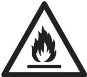
Warning symbol of a flame inside a triangle (no text or numbers)Caution: Risk of fire/ flammable materials (Required for R32/R290 units only)

natural_image
Simple line drawing of an open book with no text or symbols visibleIMPORTANT NOTE: Read this manual carefully before installing or operating your new air conditioning unit. Make sure to save this manual for future reference.
Explanation of symbols displayed on the unit(For the unit adopts R32/R290 Refrigerant only):
 | WARNING | This symbol shows that this appliance used a flammable refrigerant. If the refrigerant is leaked and exposed to an external ignition source, there is a risk of fire. |
 | CAUTION | This symbol shows that the operation manual should be read carefully. |
 | CAUTION | This symbol shows that a service personnel should be handling this equipment with reference to the installation manual. |
 | CAUTION | This symbol shows that information is available such as the operating manual or installation manual. |
⚠️ WARNINGS (for using R290/R32 refrigerant only)
- Transport of equipment containing flammable refrigerants
See transport regulations
- Marking of equipment using signs
See local regulations
- Disposal of equipment using flammable refrigerants
See national regulations.
- Storage of equipment/appliances
The storage of equipment should be in accordance with the manufacturer's instructions.
- Storage of packed (unsold) equipment
Storage package protection should be constructed such that mechanical damage to the equipment inside the package will not cause a leak of the refrigerant charge.
The maximum number of pieces of equipment permitted to be stored together will be determined by local regulations.
- Information on servicing
1) Checks to the area
Prior to beginning work on systems containing flammable refrigerants, safety checks are necessary to ensure that the risk of ignition is minimised. For repair to the refrigerating system, the following precautions shall be complied with prior to conducting work on the system.
2) Work procedure
Work shall be undertaken under a controlled procedure so as to minimise the risk of a flammable gas or vapour being present while the work is being performed.
3) General work area
All maintenance staff and others working in the local area shall be instructed on the nature of work being carried out. Work in confined spaces shall be avoided. The area around the workspace shall be sectioned off. Ensure that the conditions within the area have been made safe by control of flammable material.
4) Checking for presence of refrigerant
The area shall be checked with an appropriate refrigerant detector prior to and during work, to ensure the technician is aware of potentially flammable atmospheres. Ensure that the leak detection equipment being used is suitable for use with flammable refrigerants, i.e. non-sparking, adequately sealed or intrinsically safe.
5) Presence of fire extinguisher
If any hot work is to be conducted on the refrigeration equipment or any associated parts, appropriate fire extinguishing equipment shall be available to hand. Have a dry powder or CO2 fire extinguisher adjacent to the charging area.
6) No ignition sources
No person carrying out work in relation to a refrigeration system which involves exposing any pipe work that contains or has contained flammable refrigerant shall use any sources of ignition in such a manner that it may lead to the risk of fire or explosion. All possible ignition sources, including cigarette smoking, should be kept sufficiently far away from the site of installation, repairing, removing and disposal, during which flammable refrigerant can possibly be released to the surrounding space. Prior to work taking place, the area around the equipment is to be surveyed to make sure that there are no flammable hazards or ignition risks. No Smoking signs shall be displayed.
7) Ventilated area
Ensure that the area is in the open or that it is adequately ventilated before breaking into the system or conducting any hot work. A degree of ventilation shall continue during the period that the work is carried out. The ventilation should safely disperse any released refrigerant and preferably expel it externally into the atmosphere.
8) Checks to the refrigeration equipment
Where electrical components are being changed, they shall be fit for the purpose and to the correct specification. At all times the manufacturer's maintenance and service guidelines shall be followed. If in doubt consult the manufacturer's technical department for assistance.
The following checks shall be applied to installations using flammable refrigerants:
The charge size is in accordance with the room size within which the refrigerant containing parts are installed;
The ventilation machinery and outlets are operating adequately and are not obstructed; If an indirect refrigerating circuit is being used, the secondary circuit shall be checked for the presence of refrigerant;
Marking to the equipment continues to be visible and legible. Markings and signs that are illegible shall be corrected;
Refrigeration pipe or components are installed in a position where they are unlikely to be exposed to any substance which may corrode refrigerant containing components, unless the components are constructed of materials which are inherently resistant to being corroded or are suitably protected against being so corroded.
9) Checks to electrical devices
Repair and maintenance to electrical components shall include initial safety checks and component inspection procedures. If a fault exists that could compromise safety, then no electrical supply shall be connected to the circuit until it is satisfactorily dealt with. If the fault cannot be corrected immediately but it is necessary to continue operation, an adequate temporary solution shall be used. This shall be reported to the owner of the equipment so all parties are advised.
Initial safety checks shall include:
That capacitors are discharged: this shall be done in a safe manner to avoid possibility of sparking;
That there no live electrical components and wiring are exposed while charging, recovering or purging the system;
That there is continuity of earth bonding.
7. Repairs to sealed components
1) During repairs to sealed components, all electrical supplies shall be disconnected from the equipment being worked upon prior to any removal of sealed covers, etc. If it is absolutely necessary to have an electrical supply to equipment during servicing, then a permanently operating form of leak detection shall be located at the most critical point to warn of a potentially hazardous situation.
2) Particular attention shall be paid to the following to ensure that by working on electrical components, the casing is not altered in such a way that the level of protection is affected.
This shall include damage to cables, excessive number of connections, terminals not made to original specification, damage to seals, incorrect fitting of glands, etc.
Ensure that apparatus is mounted securely.
Ensure that seals or sealing materials have not degraded such that they no longer serve the purpose of
preventing the ingress of flammable atmospheres. Replacement parts shall be in accordance with the manufacturer's specifications.
NOTE: The use of silicon sealant may inhibit the effectiveness of some types of leak detection equipment. Intrinsically safe components do not have to be isolated prior to working on them.
8. Repair to intrinsically safe components
Do not apply any permanent inductive or capacitance loads to the circuit without ensuring that this will not exceed the permissible voltage and current permitted for the equipment in use.
Intrinsically safe components are the only types that can be worked on while live in the presence of a flammable atmosphere. The test apparatus shall be at the correct rating.
Replace components only with parts specified by the manufacturer. Other parts may result in the ignition of refrigerant in the atmosphere from a leak.
9. Cabling
Check that cabling will not be subject to wear, corrosion, excessive pressure, vibration, sharp edges or any other adverse environmental effects. The check shall also take into account the effects of aging or continual vibration from sources such as compressors or fans.
10. Detection of flammable refrigerants
Under no circumstances shall potential sources of ignition be used in the searching for or detection of refrigerant leaks. A halide torch (or any other detector using a naked flame) shall not be used.
11. Leak detection methods
The following leak detection methods are deemed acceptable for systems containing flammable refrigerants. Electronic leak detectors shall be used to detect flammable refrigerants, but the sensitivity may not be adequate, or may need re-calibration. (Detection equipment shall be calibrated in a refrigerant-free area.) Ensure that the detector is not a potential source of ignition and is suitable for the refrigerant used. Leak detection equipment shall be set at a percentage of the LFL of the refrigerant and shall be calibrated to the refrigerant employed and the appropriate percentage of gas (25 % maximum) is confirmed. Leak detection fluids are suitable for use with most refrigerants but the use of detergents containing chlorine shall be avoided as the chlorine may react with the refrigerant and corrode the copper pipe-work. If a leak is suspected, all naked flames shall be removed/ extinguished. If a leakage of refrigerant is found which requires brazing, all of the refrigerant shall be recovered from the system, or isolated (by means of shut off valves) in a part of the system remote from the leak. Oxygen free nitrogen (OFN) shall then be purged through the system both before and during the brazing process.
12. Removal and evacuation
When breaking into the refrigerant circuit to make repairs or for any other purpose conventional procedures shall be used. However, it is important that best practice is followed since flammability is a consideration. The following procedure shall be adhered to:
Remove refrigerant;
Purge the circuit with inert gas;
Evacuate;
Purge again with inert gas;
Open the circuit by cutting or brazing.
The refrigerant charge shall be recovered into the correct recovery cylinders. The system shall be flushed with OFN to render the unit safe. This process may need to be repeated several times. Compressed air or oxygen shall not be used for this task.
Flushing shall be achieved by breaking the vacuum in the system with OFN and continuing to fill until the working pressure is achieved, then venting to atmosphere, and finally pulling down to a vacuum. This process shall be repeated until no refrigerant is within the system. When the final OFN charge is used, the system shall be vented down to atmospheric pressure to enable work to take place. This operation is absolutely vital if brazing operations on the pipe-work are to take place.
Ensure that the outlet for the vacuum pump is not close to any ignition sources and there is ventilation available.
13. Charging procedures
In addition to conventional charging procedures, the following requirements shall be followed. Ensure that contamination of different refrigerants does not occur when using charging equipment. Hoses or lines shall be as short as possible to minimise the amount of refrigerant contained in them.
Cylinders shall be kept upright.
Ensure that the refrigeration system is earthed prior to charging the system with refrigerant.
Label the system when charging is complete (if not already).
Extreme care shall be taken not to overfill the refrigeration system.
Prior to recharging the system it shall be pressure tested with OFN. The system shall be leak tested on completion of charging but prior to commissioning. A follow up leak test shall be carried out prior to leaving the site.
14. Decommissioning
Before carrying out this procedure, it is essential that the technician is completely familiar with the equipment and all its detail. It is recommended good practice that all refrigerants are recovered safely. Prior to the task being carried out, an oil and refrigerant sample shall be taken in case analysis is required prior to re-use of reclaimed refrigerant. It is essential that electrical power is available before the task is commenced.
a) Become familiar with the equipment and its operation.
b) Isolate system electrically.
c) Before attempting the procedure ensure that:
Mechanical handling equipment is available, if required, for handling refrigerant cylinders; All personal protective equipment is available and being used correctly;
The recovery process is supervised at all times by a competent person;
Recovery equipment and cylinders conform to the appropriate standards.
d) Pump down refrigerant system, if possible.
e) If a vacuum is not possible, make a manifold so that refrigerant can be removed from various parts of the system.
f) Make sure that cylinder is situated on the scales before recovery takes place.
g) Start the recovery machine and operate in accordance with manufacturer's instructions.
h) Do not overfill cylinders. (No more than 80 % volume liquid charge).
i) Do not exceed the maximum working pressure of the cylinder, even temporarily.
j) When the cylinders have been filled correctly and the process completed, make sure that the cylinders and
the equipment are removed from site promptly and all isolation valves on the equipment are closed off.
k) Recovered refrigerant shall not be charged into another refrigeration system unless it has been cleaned and checked.
15. Labelling
Equipment shall be labelled stating that it has been de-commissioned and emptied of refrigerant. The label shall be dated and signed. Ensure that there are labels on the equipment stating the equipment contains flammable refrigerant.
16. Recovery
When removing refrigerant from a system, either for servicing or decommissioning, it is recommended good practice that all refrigerants are removed safely.
When transferring refrigerant into cylinders, ensure that only appropriate refrigerant recovery cylinders are employed. Ensure that the correct number of cylinders for holding the total system charge is available. All cylinders to be used are designated for the recovered refrigerant and labelled for that refrigerant (i.e. special cylinders for the recovery of refrigerant). Cylinders shall be complete with pressure relief valve and associated shut-off valves in good working order.
Empty recovery cylinders are evacuated and, if possible, cooled before recovery occurs.
The recovery equipment shall be in good working order with a set of instructions concerning the equipment that is at hand and shall be suitable for the recovery of flammable refrigerants. In addition, a set of calibrated weighing scales shall be available and in good working order. Hoses shall be complete with leak-free disconnect couplings and in good condition. Before using the recovery machine, check that it is in satisfactory working order, has been properly maintained and that any associated electrical components are sealed to prevent ignition in the event of a refrigerant release. Consult manufacturer if in doubt.
The recovered refrigerant shall be returned to the refrigerant supplier in the correct recovery cylinder, and the relevant Waste Transfer Note arranged. Do not mix refrigerants in recovery units and especially not in cylinders. If compressors or compressor oils are to be removed, ensure that they have been evacuated to an acceptable level to make certain that flammable refrigerant does not remain within the lubricant. The evacuation process shall be carried out prior to returning the compressor to the suppliers. Only electric heating to the compressor body shall be employed to accelerate this process. When oil is drained from a system, it shall be carried out safely.
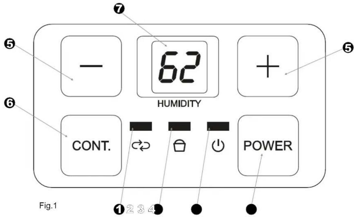
Indicator lights
① Continuous dehumidifying mode light;
② Bucket full light;
③ POWER light;
Control pads
④ Power Pad
Press to turn the dehumidifier on and off. It illuminates when the unit is switched on and turns dark when the unit is switched off. When Humidity/Temperature sensor malfunction occurs, the power light blinks at 5 times per second.
⑤ Up/Down pads
● Humidity Set Control Pads
The humidity level can be set within a range of 35%RH(Relative Humidity) to 85%RH(Relative Humidity) in 5% increments.
For drier air, press the pad and set to a lower percent value(%).
For damper air, press the pad and set a higher percent value(%).
⑥ Continue pad
Select for the dehumidifier to operate continuously for maximum dehumidification until the bucket is full. The Humidity set control pads cannot be used when Continuous operation is on. Press this pad again to cancel Continuous operation and enter dehumidifying mode.
⑦ LED Display
Shows the set % humidity level from 35% to 85%, then shows the actual (5% accuracy) room % humidity level in a range of 30% RH(Relative Humidity) to 90%RH(Relative Humidity).
Error Codes:
ES- Tube temperature sensor error;
AS- Room temperature sensor error;
Protection Codes:
P2- Bucket is full or bucket is not in the right position -- Empty the bucket and replace in the right position.
Note: When one of the above malfunctions occurs, turn off the unit, and check for any obstructions. Restart the unit, if the malfunction is still present, turn off the unit and unplug the power cord. Contact the manufacturer or its service agents or a similar qualified person for service. When reading the humidity level, please look right at the LED display window.
Other features
Bucket Full Light
Glows when the bucket is ready to be emptied, or when the bucket is removed or not replaced in the proper position.
Auto Shut Off
The dehumidifier shuts off when the bucket is full, or when the bucket is removed or not replaced in the proper position. For some models, the fan motor will continue operating for 30 seconds.
Wait 3 minutes before resuming operation
After the unit has stopped, it can not be restart opertation in the first 3 minutes. This is to protect the unit. Operation will automatically start after 3 minutes.
Auto Defrost
When frost builds up on the evaporator coils, the compressor will cycle off and the fan will continue to run until the frost disappears.
Auto-Restart
If the unit breaks off unexpectedly due to the power cut, it will restart with the previous function setting automatically when the power resumes.
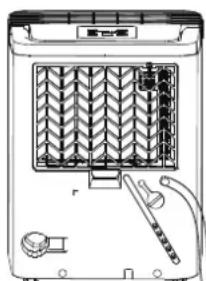
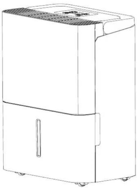
Identification of parts
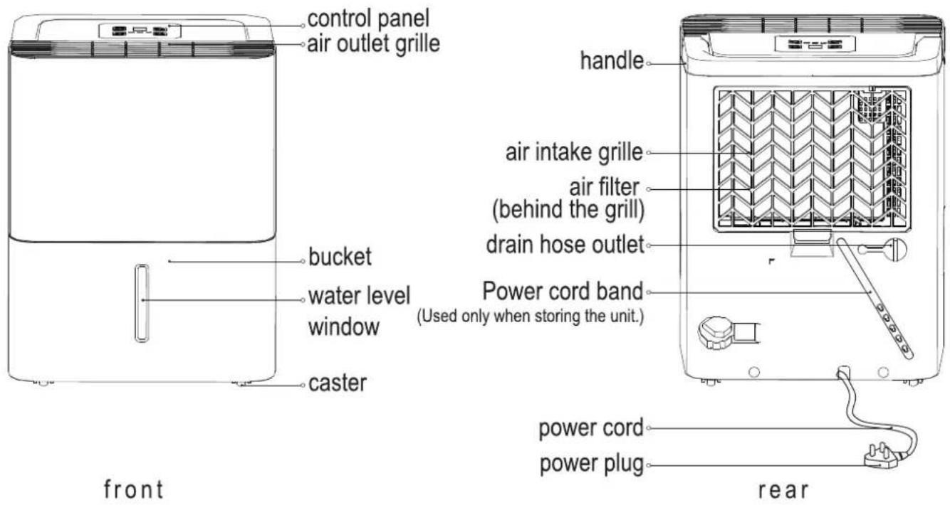
Fig.2 Fig.3
NOTE: All the pictures in the manual are for explanation purposes only. Your unit may be slightly different. The actual shape shall prevail. The operations and functions are the same.
Positioning the unit
A dehumidifier operating in a basement will have little or no effect in drying an adjacent enclosed storage area, such as a closet, unless there is adequate circulation of air in and out of the area.
- Do not use outdoors.
- This dehumidifier is intended for indoor residential applications only. This dehumidifier should not be used for commercial or industrial applications.
- Place the dehumidifier on a smooth, level floor strong enough to support the unit with a full bucket of water.
- Allow at least 20cm of air space on all sides of the unit for good air circulation.
- Place the unit in an area where the temperature will not fall below 5^ C(41°F). The coils can become covered with frost at temperatures below 5^ C(41°F), which may reduce performance.
- Place the unit away from the clothes dryer, heater or radiator.
- Use the unit to prevent moisture damage anywhere books or valuables are stored.
- Use the dehumidifier in a basement to help prevent moisture damage.
- The dehumidifier must be operated in an enclosed area to be most effective.
- Close all doors, windows and other outside openings to the room.
When using the unit
- When first using the dehumidifier, operate the unit continuously 24 hours.
- This unit is designed to operate with a working environment between 5°C/41 F and 32 C/90 F, and between 30%(RH) and 80%(RH).
- If the unit has been switched off and needs to be switched on again quickly, allow approximately three minutes for the correct operation to resume.
- Do not connect the dehumidifier to a multiple socket outlet, which is also being used for other electrical appliances.
- Select a suitable location, making sure you have easy access to an electrical outlet.
- Plug the unit into a electrical socket-outlet with earth connection.
- Make sure the Water bucket is correctly fitted otherwise the unit will not operate properly.
NOTE: When the water in the bucket reaches to a certain level, please be careful to move the machine to avoid it falling down.
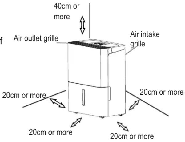
Fig.4
Casters(Install at four points on the bottom of unit)
- Do not force casters to move over carpet, nor move the unit with water in the bucket. (The unit may tip over and spill water.)
NOTE: Casters is optional, some models without.
Removing the collected water
There are two ways to remove collected water.
1. Use the bucket
- When the bucket is full, the Full indicator light will illuminate, the digital display shows P2.
- Slowly pull out the bucket. Grip the left and right handles securely, and carefully pull out straight so water does not spill. Do not put the bucket on the floor because the bottom of the bucket is uneven. Otherwise the bucket will fall and cause the water to spill.
- Throw away the water and replace the bucket. The bucket must be in place and securely seated for the dehumidifier to operate.
-
The machine will restore to its original state when the bucket is replaced in its correct position.
-
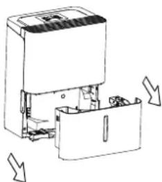
Pull out the bucket a little.
natural_image
Diagram of a mechanical device with directional arrows indicating movement or force (no text or symbols present)Fig.5
- Hold both sides of the bucket with even strength, and pull it out from the unit.
natural_image
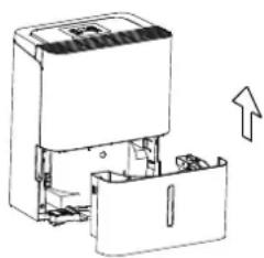
Technical line drawing of a mechanical device with an arrow indicating upward motion (no text or symbols present)Fig.6
- Pour the water out.
NOTES:
- When you remove the bucket, do not touch any parts inside of the unit. Doing so may damage the product.
- Be sure to push the bucket gently all the way into the unit. Banging the bucket against anything or failing to push it in securely may cause the unit not to operate.
- When you remove the bucket, if there is some water in the unit you must dry it.
Removing the collected water
2. Continuous draining
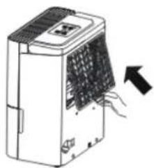
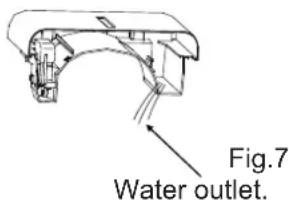
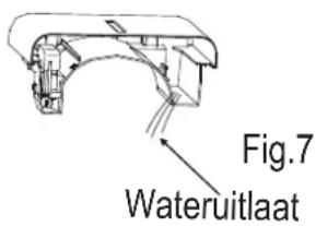
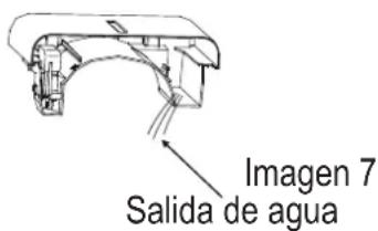
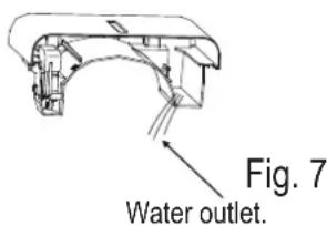
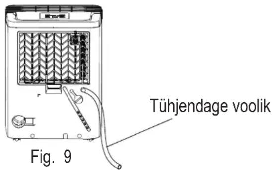
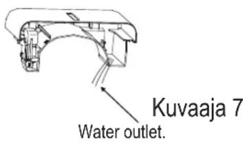
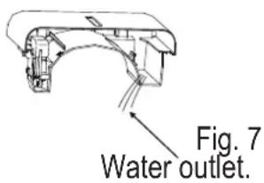
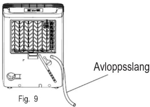
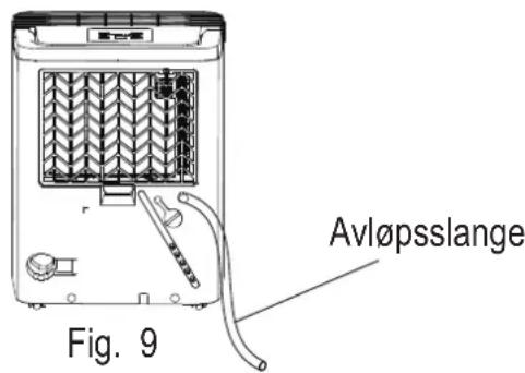
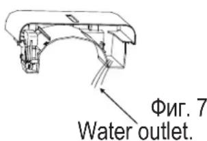
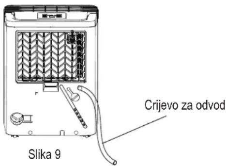
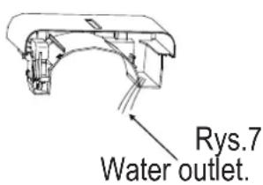
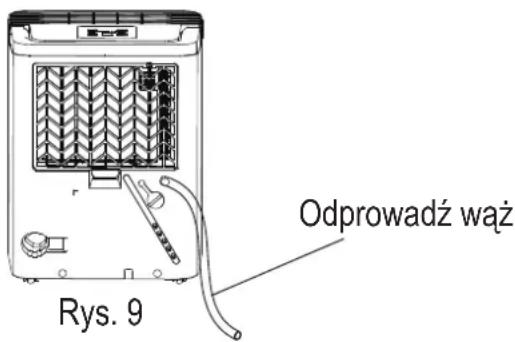
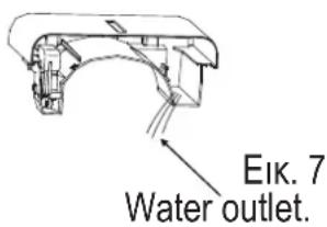
- Water can be automatically emptied into a floor drain by attaching the unit with a water hose (not included).
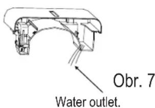
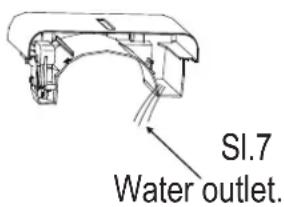
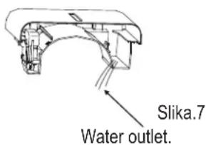
- Remove the rubber plug from the back drain hose outlet. Attach a drain hose(ID=13.5mm) and lead it to the floor drain or a suitable drainage facility(see Fig.8 and Fig.9).
• Make sure the hose is secure so there are no leaks.
- Direct the hose toward the drain, making sure that there are no kinks that will stop the warter flowing.
- Place the end of the hose into the drain and make sure the end of the hose is level or down to let the water flow smoothly. Donever let it up.
- Make sure the water hose is lower than the drain hose outlet.
- Select the desired humidity setting and fan speed on the unit for continuous draining to start.
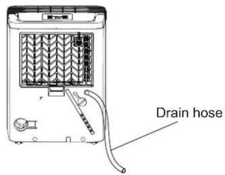
NOTE: When the continuous drain feature is not being used, remove the drain hose from the outlet and attach the rubber plug back to the drain outlet
Care and cleaning of the dehumidifier
Turn the dehumidifier off and remove the plug from the wall outlet before cleaning.
1. Clean the Grille and Case
- Use water and a mild detergent. Do not use bleach or abrasives.
- Do not splash water directly onto the main unit. Doing so may cause an electrical shock, cause the insulation to deteriorate, or cause the unit to rust.
- The air intake and outlet grilles get soiled easily, so use a vacuum attachment or brush to clean.
2. Clean the bucket
Every few weeks, clean the bucket to prevent growth of mold, mildew and bacteria. Partially fill the bucket with clean water and add a little mild detergent. Swish it around in the bucket, empty and rinse.
NOTE: Do not use a dishwasher to clean the bucket. After clean, the bucket must be in place and securely seated for the dehumidifier to operate.
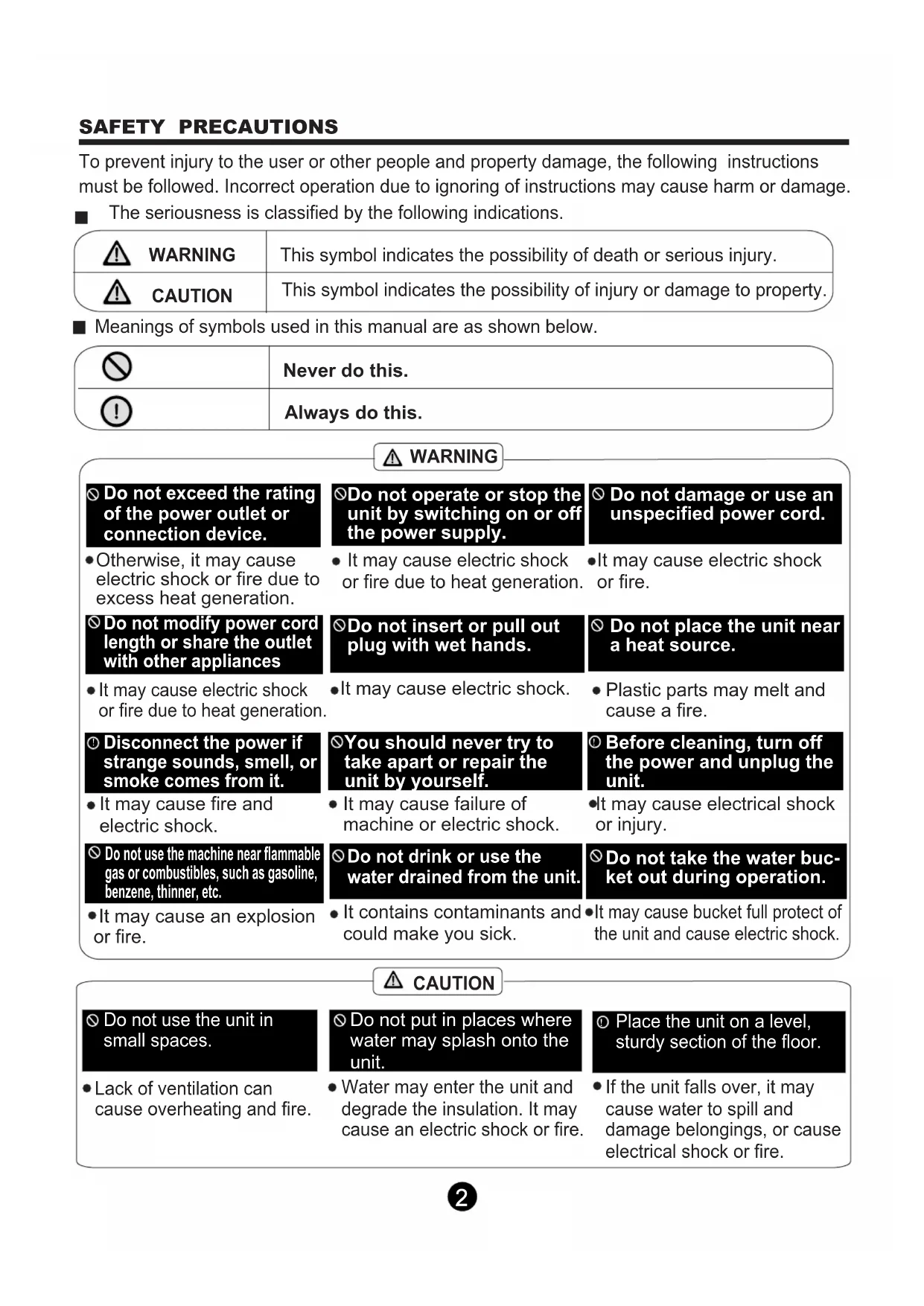
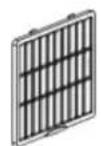
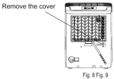
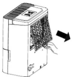
3. Clean the air filter
The air filter behind the front grille should be checked and cleaned at least every two weeks or more often if necessary.
NOTE: DO NOT RINSE OR PUT THE FILTER IN AN AUTOMATIC DISHWASHER.
To remove:
● Grip the tab on the filter and pull it upward, then pull it out as shown in Fig.10.
- Clean the filter with warm, soapy water. Rinse and let the filter dry before replacing it. Do not clean the filter in a dishwasher.
To attach:
- Insert the air filter into the unit from underside to upside.
NOTE: When re-install the filter, please pat the middle buckles of the filter first and then pat the bottom bukcle.
natural_image
Diagram of a device emitting heat or smoke from a fan array (no text or symbols)Fig. 10
CAUTION:
DO NOT operate the dehumidifier without a filter because dirt and lint will clog it and reduce performance.
NOTE: The cabinet and front may be dusted with an oil-free cloth or washed with a cloth dampened in a solution of warm water and mild liquid dishwashing detergent. Rinse thoroughly and wipe dry. Never use harsh cleansers, wax or polish on the cabinet front. Be sure to wring excess water from the cloth before wiping around the controls. Excess water in or around the controls may cause damage to the unit.
4. When not using the unit for long time periods
- After turning off the unit, wait one day before emptying the bucket.
- Clean the main unit, water bucket and air filter.
• Cover the unit with a plastic bag. - Store the unit upright in a dry, well-ventilated place.
Before calling for service, review the chart below first yourself.
| Problem | What to check |
| Unit does not start |  Make sure the dehumidifier s plug is pushed completely into the outlet.Check the house fuse/circuit breaker box.Dehumidifier has reached its preset level or bucket is full.Bucket is not in the proper position. Make sure the dehumidifier s plug is pushed completely into the outlet.Check the house fuse/circuit breaker box.Dehumidifier has reached its preset level or bucket is full.Bucket is not in the proper position. |
| Dehumidifier does not dry the air as it should |  Did not allow enough time to remove the moisture.Make sure there are no curtains, blinds or furniture blocking the front or back of the dehumidifier.The humidity selector may not be set low enough.Check that all doors, windows and other openings are securely closed.Room temperature is too low, below 5°C(41°F).There is a kerosene heater or something giving off water vapor in the room. Did not allow enough time to remove the moisture.Make sure there are no curtains, blinds or furniture blocking the front or back of the dehumidifier.The humidity selector may not be set low enough.Check that all doors, windows and other openings are securely closed.Room temperature is too low, below 5°C(41°F).There is a kerosene heater or something giving off water vapor in the room. |
| The unit makes a loud noise when operating |  The air filter is clogged.The unit is tilted instead of upright as it should be.The floor surface is not level. The air filter is clogged.The unit is tilted instead of upright as it should be.The floor surface is not level. |
| Frost appears on the coils |  This is normal. The unit has Auto defrost feature. This is normal. The unit has Auto defrost feature. |
| Water on floor |  Hose to connector or hose connection may be loose.Intend to use the bucket to collect water, but the back drain plug is removed. Hose to connector or hose connection may be loose.Intend to use the bucket to collect water, but the back drain plug is removed. |
| ES, AS or P2 appear in the display |  These are error codes and protection codes. See the CONTROL PADS ON THE DEHUMIDIFIER section. These are error codes and protection codes. See the CONTROL PADS ON THE DEHUMIDIFIER section. |
The design and specifications are subject to change without prior notice for product improvement. Consult with the sales agency or manufacturer for details. Any updates to the manual will be uploaded to the service website, please check for the latest version.
LUCHTONTVOCHTIGER
GEBRUIKERSHANDLEIDING
natural_image
Line drawing of a portable air purifier device with control panel and wheels (no text or symbols)natural_image
Symbol of a trash bin crossed with no visible text or labelsVEILIGHEIDSMAATREGELEN
Waarschuwing 2
Let Op 2
Elektronische informatie ....4
WERKEN MET HET APPARAAT
PROBLEEMOPLOSSING TIPS
Probleemoplossing tips 18
natural_image
Warning symbol of a flame inside a triangle (no text or numbers)natural_image
Simple line drawing of an open book with no text or symbols visiblenatural_image
Diagram of a device with internal components and directional arrows indicating movement (no text or symbols)Fig.5
natural_image
Technical line drawing of a mechanical device with internal components and an upward arrow indicating motion (no text or symbols)Fig.6
- Giet het water weg.
OPMERKINGEN:
natural_image
Diagram of a device with heat exchanger and airflow arrow (no text or symbols)Fig. 10
LET OP:
natural_image
Line drawing of a portable air purifier device with control panel and wheels (no text or symbols)natural_image
Symbol of a trash bin crossed with no text or numbers, representing waste sorting or disposal (no text present)
CONTENIDOS
natural_image
Warning symbol of a flame inside a triangle (no text or numbers)natural_image
Simple line drawing of an open book with no text or symbols visiblenatural_image
Diagram of a device with internal components and directional arrows indicating movement (no text or symbols)Imagen 5
natural_image
Diagram of a device with internal components and an upward arrow indicating motion (no text or symbols)Imagen 6
- Vacíe el agua.
natural_image
Diagram of a portable electronic device with a grid-patterned cover and directional arrow (no text or symbols)Imagen 10
PRECAUCIÓN:
natural_image
Line drawing of a portable air purifier device with control panel and wheels (no text or symbols)natural_image
Symbol of a trash bin crossed with no text or numbers, representing waste sorting or disposal (no text present)SIKKERHEDSFORANSTALTNINGER
Advarsel....2
Forsigtig....2
Elektrisk information 4
natural_image
Simple line drawing of an open book with no text or symbols visiblenatural_image
Diagram of an industrial device with internal components and directional arrows indicating flow or movement (no text or symbols)Fig. 5
natural_image
Technical line drawing of a mechanical device with internal components and an upward arrow indicating motion (no text or symbols)Fig. 6
- Hæld vandet ud.
BEMÆRK:
natural_image
Diagram of a portable electronic device with ventilation grille and cooling fan, showing airflow direction (no text or symbols)Fig. 10
FORSIGTIG:
natural_image
Line drawing of a portable air purifier device with lid and wheels (no text or symbols)natural_image
Symbol of a trash bin crossed with no visible text or labelsOHUTUSJUHEND
Hoiatus 2
Ettevaatusabinõud 2
Elektriteave 4
natural_image
Warning symbol of a flame inside a triangle (no text or numbers)natural_image
Simple line drawing of an open book with no text or symbols visiblenatural_image
Diagram of a device with internal components and directional arrows indicating movement (no text or symbols)Fig.5
natural_image
Technical line drawing of a mechanical device with internal components and an upward arrow indicating motion (no text or symbols)Fig.6
- Kallake vesi välja.
MÄRKUSED:
natural_image
Technical diagram of a device interior showing internal structure with no visible text or symbolsFig. 8
natural_image
Diagram of a portable air conditioner unit with airflow direction indicated by an arrow (no text or symbols)Fig. 10
ETTEVAATUS:
natural_image
Line drawing of a portable air purifier device with control panel and wheels (no text or symbols)natural_image
Symbol of a trash bin crossed with no visible text or labelsTURVALLISUUSTOIMET
Varoitus....2
VAROVAISUUS 2
natural_image
Warning symbol of a flame inside a triangle (no text or numbers)natural_image
Simple line drawing of an open book with no text or symbols visiblenatural_image
Diagram of an industrial device with internal components and directional arrows indicating flow or movement (no text or symbols)Kuvaaja 5
natural_image
Technical line drawing of a mechanical device with internal components and an upward arrow indicating motion (no text or symbols)Kuvaaja 6
- Kaada vesi ulos.
natural_image
Diagram of a portable electronic device with ventilation grilles and airflow direction arrow (no text or symbols)Kuvaajann 10
VAROVAISUUS:
natural_image
Line drawing of a portable air purifier device with control panel and wheels (no text or symbols)natural_image
Symbol of a trash bin crossed with no visible text or labelsSDKERHETSETGDRDER
Varning 2
Larm 2
Elektrisk information 4
natural_image
Warning symbol of a flame inside a triangle (no text or numbers)natural_image
Simple line drawing of an open book with no text or symbols visiblenatural_image
Diagram of a device with internal components and directional arrows indicating movement (no text or symbols)Fig. 5
natural_image
Technical line drawing of a mechanical device with internal components and an upward arrow indicating motion (no text or symbols)Fig. 6
- Häll ut vattnet.
OBS:
Fig. 8
natural_image
Diagram of a portable electronic device with ventilation grilles and airflow direction arrow (no text or symbols)Fig. 10
Larm:
natural_image
Line drawing of a portable air purifier device with control panel and wheels (no text or symbols)natural_image
Symbol of a trash bin crossed with no visible text or labelsSIKKERHETSREGLER
Advarsel....2
Forsiktig 2
natural_image
Warning symbol of a flame inside a triangle (no text or numbers)Forsiktig: Brannfare/brennbart materiale (Påkrevd kun for R32/R290 enheter)

natural_image
Simple line drawing of an open book with no text or symbols visiblenatural_image
Diagram of a device with internal components and directional arrows indicating movement (no text or symbols)Fig. 5
natural_image
Technical line drawing of a mechanical device with an arrow indicating upward motion (no text or symbols present)Fig. 6
- Tøm ut vannet.
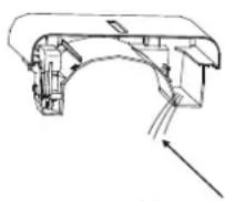
Fig. 7
Water outlet.
MERKNADER:
Fig. 8
natural_image
Diagram of a portable electronic device with ventilation grilles and airflow direction arrow (no text or symbols)Fig. 10
FORSIKTIG:
natural_image
Line drawing of a portable air purifier device with control panel and wheels (no text or symbols)natural_image
Symbol of a trash bin crossed with diagonal lines, representing no waste or discharge (no text or labels)
ПРЕДПАЗНИ МЕРКИ
Предупреждение....2
Внимание....2
natural_image
Warning symbol of a flame inside a triangle (no text or numbers)natural_image
Simple line drawing of an open book with no text or symbols visiblenatural_image
Diagram of a device with internal components and directional arrows indicating movement (no text or symbols)Фиг. 5
natural_image
Technical line drawing of a mechanical device with internal components and an upward arrow indicating motion (no text or symbols)Фиг. 6
- Изсипете водата.
ЗАБЕЛЕЖКА:
natural_image
Diagram of a device with heat exchanger and airflow arrow (no text or symbols)Фиг. 10
Внимание:
natural_image
Line drawing of a portable air purifier device with control panel and ventilation grille (no text or symbols)natural_image
Symbol of a trash bin crossed with no visible text or labelsBEZPEČNOSTNÍ OPATŘENÍ
Varování 2
Upozornění 2
natural_image
Simple line drawing of an open book with no text or symbols visiblenatural_image
Diagram of a device with internal components and directional arrows indicating movement (no text or symbols)Obr. 5
natural_image
Technical line drawing of a mechanical device with internal components and an upward arrow indicating motion (no text or symbols)Obr. 6
- Vylejte vodu ven.
POZNÁMKY:
natural_image
Diagram of a portable electronic device with ventilation grilles and airflow direction arrow (no text or symbols)Obr. 10
POZOR:
natural_image
Line drawing of a portable air purifier device with control panel and wheels (no text or symbols)natural_image
Symbol of a trash bin crossed with no visible text or labelsVARNOSTNI UKREPI
Opozorilo 2
Pozor 2
natural_image
Warning symbol of a flame inside a triangle (no text or numbers)Pozor: Nevarnost požara / vnetljivih snovi (samo za naprave R32 / R290)

natural_image
Simple line drawing of an open book with no text or symbols visiblenatural_image
Diagram of a mechanical device with internal components and directional arrows indicating motion (no text or symbols)Sl.5
- Držite obe strani vedra enakomerno in jo izvlecite iz naprave.

natural_image
Technical line drawing of a mechanical device with internal components and an upward arrow indicating motion (no text or symbols)Sl.6
- Izlijemo vodo.
Opomba:
natural_image
Diagram of a device with heat exchanger and airflow direction arrow (no text or symbols)Sl. 10
Pozor:
natural_image
Line drawing of a portable air purifier device with lid and wheels (no text or symbols)natural_image
Symbol of a trash bin crossed with no visible text or labelsBIZTONSÁGI ÓVINTÉZKEDÉSEK
Figyelmeztetés 2
Vigyázat....2
natural_image
Warning symbol of a flame inside a triangle (no text or numbers)natural_image
Simple line drawing of an open book with no text or symbols visiblenatural_image
Diagram of a device with internal components and directional arrows indicating movement (no text or symbols)- ábra
natural_image
Technical line drawing of a mechanical device with internal components and an upward arrow indicating motion (no text or symbols)- ábra
3 Öntse ki a vizet.
7. ábra
Water outlet.
natural_image
Diagram of a portable electronic device with ventilation slots and airflow direction arrow (no text or symbols)- ábra
Vigyázat:
natural_image
Line drawing of a portable air purifier device with control panel and wheels (no text or symbols)natural_image
Symbol of a trash bin crossed with no visible text or labelsMJERE SIGURNOSTI
Upozorenje 2
Oprez 2
Elektro podaci 4
UPOZORENJA (samo za korištenje R290/R32 rashladnih sredstava) 5
KONTROLNI GUMBI NA ODVLAŽIVAČU ZRAKA
Kontrolni gumbi....11
Ostale funkcije....12
IDENTIFIKACIJA DIJELOVA
natural_image
Warning symbol of a flame inside a triangle (no text or numbers)natural_image
Simple line drawing of an open book with no text or symbols visibleVAŽNA NAPOMENA: Pažljivo pročitajte ove upute za uporabu prije instaliranja ili uporabe vašeg novog klima uređaja. Sačuvajte ovaj priručnik za kasniju uporabu.
Objašnjenje simbola prikazanih na uređaju (Za uređaj se koristi samo R32/R290 rashladno sredstvo):
| UPOZORENJE | Ovaj simbol pokazuje da ovaj uređaj koristi lako zapaljivo rashladno sredstvo. Ako rashladno sredstvo curi i izloženo je vanjskom izvoru paljenja, postoji rizik od požara. | |
| OPREZ | Ovaj simbol pokazuje da treba pažljivo pročitate upute za uporabu. | |
| OPREZ | Ovaj simbol pokazuje da osoblje za servisiranje treba nositi ovu opremu preporučenu u uputama za uporabu. | |
| OPREZ | Ovaj simbol pokazuje da su na raspolaganju takve informacije, kao upute za uporabu ili upute za instalaciju. |
⚠ UPOZORENJA (samo za korištenje R290/R32 rashladnih sredstava)
natural_image
Diagram of a device with internal components and directional arrows indicating movement (no text or symbols)natural_image
Technical line drawing of a mechanical device with an arrow indicating upward motion (no text or symbols present)Slika.6
- Ispraznite vodu.
NAPOMENA:
- Kada uklonite spremnik, nemojte dodirivati bilo koji dio unutar uređaja. To bi moglo dovesti do oštećenja proizvoda.
- Morate sve vrijeme pažljivo umetati spremnik u uređaj. Ako udarite spremnik u bilo što ili ako ga ne stavite bezbjedno unutra, može doći do toga da uređaj ne funkcionira.
- Kada uklonite spremnik, ako u uređaju ostane vode, morate je osušiti.
Uklanjanje prikupljene vode
2. Kontinuirani odvod
Slika 8
NAPOMENA: Kada se ne koristi funkcija kontinuiranog isušivanja, uklonite crijevo odvoda iz ispusta i zakačite gumeni zatvarač na ispust odvoda
natural_image
Diagram of a portable electronic device with ventilation grilles and airflow direction arrow (no text or symbols)Slika 10
Oprez:
NE koristite odvlživač zraka bez filtra jer će se prljavština gomilati i umanjiti učinkovitost.
NAPOMENA: Sa kućišta i prednjeg dijela prašina se može ukloniti s pomoću krpe bez ulja ili oprati s pomoću krpe namočene u mješavinom tople vode i blagog deterdženta za perilicu za suđe. Temeljito isperite i obrišite. Nikada ne koristite tvrde deterdžente, vosak ili lak na prednjoj strani kućišta. Prije no počnete brisati kontrole, pobrinite se da iz krpre iscedite višak vode. Višak vode u kontrolama ili oko njih može dovesti do oštećenja uređaja.
natural_image
Line drawing of a portable air purifier device with control panel and wheels (no text or symbols)natural_image
Symbol of a trash bin crossed with a diagonal line, representing no waste or discharge (no text or labels)
ŚRODKI OSTROŻNOŚCI
Ostrzeżenie 2
Uwaga 2
natural_image
Warning symbol of a flame inside a triangle (no text or numbers)natural_image
Simple line drawing of an open book with no text or symbols visiblenatural_image
Technical line drawing of a mechanical device with directional arrows indicating movement or force (no text or symbols)Rys.5
natural_image
Technical line drawing of a mechanical device with an arrow indicating upward motion (no text or symbols present)Rys.6
- Wylej wodę.
Rys. 8
natural_image
Diagram of a portable electronic device with ventilation grille and cooling fan, showing airflow direction (no text or symbols)Rys. 10
UWAGA:
natural_image
Line drawing of a portable air purifier device with lid and wheels (no text or symbols)natural_image
Symbol of a trash bin crossed with no visible text or labelsΜΕΤΡΑ ΑΣΦΑΛΕΙΑΣ
ΠΡΟΕΙΔΟΠΟΙΗΣΗ 2
ΠΡΟΣΟΧΗ 2
natural_image
Simple line drawing of an open book with no text or symbols visiblenatural_image
Diagram of an industrial device with internal components and directional arrows indicating movement (no text or symbols)Eik. 5
natural_image
Technical line drawing of a mechanical device with internal components and an upward arrow indicating motion (no text or symbols)Eik. 6
- Βγάλτε το νερό έξω.
ΣΗΜΕΙΩΣΕΙΣ:
natural_image
Diagram of a portable electronic device with ventilation slots and airflow direction arrow (no text or symbols)Eik. 10
Προσοχή:
Technical changes, errors, mistakes
and printing errors reserved. Version 04/2019

- MISURE DI SICUREZZA
- NOTA:
- Attenzione:
- PRÏCAUTIONS DE SÏCURITI
- ATTENTION:
- When using this dehumidifier in the European countries, the following information must be followed:
- CONTENTS
- SAFETY PRECAUTIONS
- CONTROL PADS ON THE DEHUMIDIFIER
- IDENTIFICATION OF PARTS
- OPERATING THE UNIT
- CARE AND MAINTENANCE
- TROUBLESHOOTING TIPS
- Read This Manual
- WARNING
- CAUTION
- Electrical Information
- Take note the fuse specifications
- WARNINGS (for using R290/R32 refrigerant only)
- ⚠️ WARNINGS (for using R290/R32 refrigerant only)
- 7) Ventilated area
- 8) Checks to the refrigeration equipment
- 9) Checks to electrical devices
- Repairs to sealed components
- Repair to intrinsically safe components
- Cabling
- Detection of flammable refrigerants
- Leak detection methods
- Removal and evacuation
- Charging procedures
- Decommissioning
- Labelling
- Recovery
- Indicator lights
- Control pads
- ④ Power Pad
- ⑤ Up/Down pads
- ⑥ Continue pad
- ⑦ LED Display
- Other features
- Bucket Full Light
- Auto Shut Off
- Wait 3 minutes before resuming operation
- Auto Defrost
- Auto-Restart
- Positioning the unit
- When using the unit
- Casters(Install at four points on the bottom of unit)
- Removing the collected water
- There are two ways to remove collected water.
- Use the bucket
- NOTES:
- Continuous draining
- Care and cleaning of the dehumidifier
- Clean the Grille and Case
- Clean the bucket
- Clean the air filter
- To remove:
- To attach:
- CAUTION:
- When not using the unit for long time periods
- LUCHTONTVOCHTIGER
- GEBRUIKERSHANDLEIDING
- VEILIGHEIDSMAATREGELEN
- WERKEN MET HET APPARAAT
- PROBLEEMOPLOSSING TIPS
- OPMERKINGEN:
- LET OP:
- CONTENIDOS
- PRECAUCIÓN:
- SIKKERHEDSFORANSTALTNINGER
- BEMÆRK:
- FORSIGTIG:
- OHUTUSJUHEND
- MÄRKUSED:
- ETTEVAATUS:
- TURVALLISUUSTOIMET
- VAROVAISUUS:
- SDKERHETSETGDRDER
- OBS:
- Larm:
- SIKKERHETSREGLER
- MERKNADER:
- FORSIKTIG:
- ПРЕДПАЗНИ МЕРКИ
- ЗАБЕЛЕЖКА:
- Внимание:
- BEZPEČNOSTNÍ OPATŘENÍ
- POZNÁMKY:
- POZOR:
- VARNOSTNI UKREPI
- Opomba:
- BIZTONSÁGI ÓVINTÉZKEDÉSEK
- Vigyázat:
- MJERE SIGURNOSTI
- KONTROLNI GUMBI NA ODVLAŽIVAČU ZRAKA
- IDENTIFIKACIJA DIJELOVA
- ⚠ UPOZORENJA (samo za korištenje R290/R32 rashladnih sredstava)
- NAPOMENA:
- Uklanjanje prikupljene vode
- Kontinuirani odvod
- Oprez:
- ŚRODKI OSTROŻNOŚCI
- UWAGA:
- ΜΕΤΡΑ ΑΣΦΑΛΕΙΑΣ
- ΣΗΜΕΙΩΣΕΙΣ:
- Προσοχή:
Brand : COMFEE
Model : MDDN10DEN7
Category : Dehumidifier