
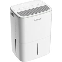
MDDA-30DEN7-SD - Dehumidifier COMFEE - Free user manual and instructions
Find the device manual for free MDDA-30DEN7-SD COMFEE in PDF.

| Product Type | Dehumidifier |
| Brand | Comfee |
| Model | MDDA-30DEN7-SD |
| Dehumidification Capacity | 30 L/day (at 30°C, 80% RH) |
| Recommended Area | Up to 60 m² |
| Water Tank | 5 L (removable) |
| Power Consumption | 500 W (approx.) |
| Power Supply | 220-240 V ~ 50 Hz |
| Refrigerant | R290 (flammable) |
| Dimensions (W x D x H) | 35 x 25 x 55 cm (approx.) |
| Weight | 15 kg (approx.) |
| Noise Level | 50 dB (approx.) |
| Operating Modes | Adjustment (35-85% RH), Continuous, Drying, Comfort (45-55% RH) |
| Timer | 0.5 to 24 h (start/stop) |
| Fan Speed | Low and High |
| Connectivity | Wi-Fi (SmartHome app) |
| Ionizer Function | Yes (optional) |
| Air Filter | Washable (clean every 2 weeks) |
| Auto Shut-off | Tank full or removed |
| Auto Restart | After power outage |
| Anti-frost Protection | Auto defrost |
| Continuous Drain | Possible via hose (diameter ≥ 5/16 in, female thread 1 in) |
| Spare Parts | Filter, tank, drain hose, Smart kit |
| Warranty | 2 years |
Frequently Asked Questions - MDDA-30DEN7-SD COMFEE
User questions about MDDA-30DEN7-SD COMFEE
0 question about this device. Answer the ones you know or ask your own.
Ask a new question about this device
Download the instructions for your Dehumidifier in PDF format for free! Find your manual MDDA-30DEN7-SD - COMFEE and take your electronic device back in hand. On this page are published all the documents necessary for the use of your device. MDDA-30DEN7-SD by COMFEE.
USER MANUAL MDDA-30DEN7-SD COMFEE
natural_image
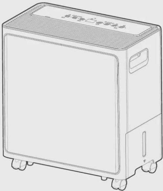
Line drawing of a portable air purifier with wheels and ventilation slots (no text or symbols)DEHUMIDIFIER
USER MANUAL
MODEL NUMBER
MDDA-30DEN7-SD
Warning notices: Before using this product, please read this manual carefully and keep it for future reference. The design and specifications are subject to change without prior notice for product improvement.
Consult with your dealer or manufacturer for details.
The diagram above is just for reference. Please take the appearance of the actual product as the standard.
CONTENTS
Safety Precautions 02
Get to know your product 10
Get to know your features 12
Dump the collected water 15
Care and Maintenance 18
Troubleshooting 20
Disposal and Recycling 20
Safety Precautions
It's really important you read Safety Precautions Before Operation and Installation Incorrect installation due to ignoring instructions can cause serious damage or injury. The seriousness of potential damage or injuries is classified as either a WARNING or CAUTION.
Explanation of Symbols

WARNING
The signal word indicates a hazard with a high level of risk which, if not avoided, may result in serious injury or death.

CAUTION
The signal word indicates a hazard with a low degree of risk which, if not avoided, may result in minor or moderate injury.
Read these operating instructions carefully and attentively before using/commissioning the unit and keep them in the immediate vicinity of the installation site or unit for later use!

WARNING
- Do not exceed the rating of the power outlet or connection device.
- Do not operate or stop the unit by switching on or off the power.
- Do not damage or use an unspecified power cord.
- Do not modify power cord length or share the outlet with other appliances.
- Do not insert or pull out plug with wet hands.
- Do not install the appliance in a location that may be exposed to combustible gas.
- Do not place the unit near a heat source.
- Disconnect the power if strange sounds, smell, or smoke comes from it.
- You should never try to take apart or repair the unit by yourself.
- Before cleaning, turn off the power and unplug the unit.
- Do not use the machine near flammable gas or combustibles, such as gasoline, benzene, thinner, etc.
- Do not drink or use the water drained from the unit.
- Do not take the water bucket out during operation.
- Do not use the unit in small spaces.
- Do not put in places where water may splash onto the unit.
- Place the unit on a level, sturdy section of the floor.
- Do not cover the intake or exhaust openings with cloths or towels.
- Care should be taken when using the unit in a room with the following persons: infants, children, elderly people, and people not sensitive to humidity.
- Do not use in areas where chemicals are handled.
- Never insert your finger or other foreign objects into grills or openings. Take special care to warn children of these dangers.
- Do not place heavy object on the power cord and take care so that the cord is not compressed.
- Do not climb up on or sit on the unit.
• Always insert the filters securely. Clean filter once every two weeks. - If water enters the unit, turn the unit off and disconnect the power, contact a qualified service technician.
- Do not place flower vases or other water container on top of the unit.
- Do not use extension cords.

CAUTION
- This appliance can be used by children aged from 8 years and above and person with reduced physical, sensory or mental capabilities or lack of experience and knowledge if they have been given supervision or instruction concerning use of the appliance in a safe way and understand the hazards involved. Children shall not play with the appliance. Cleaning and user maintenance shall not be made by children without supervision. (be applicable for the European Countries)
- This appliance is not intended for use by persons (including childern) with reduced physical, sensory or mental capabilities or lack of experience and knowledge, unless they have been given supervision or instruction concerning use of the appliance by a person responsible for their safety. Children should be supervised to ensure that they do not play with the appliance. (be applicable for other countries except the European Countries)
- If the supply cord is damaged, it must be replaced by the manufacturer, its service agent or similarly qualified persons in order to avoid a hazard.
- Prior to cleaning or other maintenance, the appliance must be disconnected from the supply mains.
- Do not install the appliance in a location that may be exposed to combustible gas.
- If combustible gas accumulates around the unit, it may cause fire. If the appliance is knocked over during use, turn off the unit and unplug it from the main power supply immediately. Visually inspect the unit to ensure there is no damage. If you suspect the unit has been damaged, contact a technician or customer service for assistance.
- In a thunderstorm, the power must be cut off to avoid damage to the machine due to lightning.
- Do not run cord under carpeting. Do not cover cord with throw rugs, runners, or similar coverings. Do not route cord under furniture or appliances. Arrange cord away from traffic area and where it will not be tripped over.
- Do not operate unit with a damaged cord or plug. Discard unit or return to an authorized service facility for examination and/or repair.
- To reduce the risk of fire or electric shock, do not use this fan with any solid-state speed control device.
- The appliance shall be installed in accordance with national wiring regulations.
- Contact the authorised service technician for repair or maintenance of this unit.
- Turn off the product when not in use.

CAUTION
- The manufactures nameplate is located on the rear panel of the unit and contains electrical and other technical data specific to this unit.
- Be sure the unit is properly grounded. To minimize shock and fire hazards, proper grounding is important. The power cord is equipped with a three-prong grounding plug for protection against shock hazards.
- Your unit must be used in a properly grounded wall receptacle. If the wall receptacle you intend to use is not adequately grounded or protected by a time delay fuse or circuit breaker(please refer to the nameplate for the electrical data), have a qualified electrician install the proper receptacle.
- Do not operate your appliance in a wet room such as a bathroom or laundry room. The unit's circuit board(PCB) is designed with a fuse to provide overcurrent
- protection. The specifications of the fuse are printed on the circuit board, such as: T3.15A/250V (or 350V), etc.
Note about Fluorinated Gasses(Not applicable to the unit using R290 Refrigerant)
- Fluorinated greenhouse gases are contained in hermetically sealed equipment. For specific information on the type, the amount and the CO2 equivalent in tonnes of the fluorinated greenhouse gas(on some models), please refer to the relevant label on the unit itself.
- Installation, service, maintenance and repair of this unit must be performed by a certified technician.
- Product uninstallation and recycling must be performed by a certified technician.

CAUTION
- this appliance contains a UV-C lamp, read the maintenance instructions before opening the appliance;
- unintended use of the appliance or damage to the housing may result in the escape of dangerous UV-C radiation.
• UV-C radiation may, even in small doses, cause harm to the eyes and skin; - appliances that are obviously damaged must not be operated;
• do not operate UV-C lamps outside of the appliance; - UV-C barriers bearing the ultraviolet radiation hazard symbol should not be removed;
- WARNING: This appliance contains an UV emitter. Do not stare at the light source;
The UV-C lamp cannot be cleaned, repaired and replaced.

WARNING for Using R290/R32 Refrigerant
- Do not use means to accelerate the defrosting process or to clean, other than those recommended by the manufacturer.
- The appliance shall be stored in a room without continuously operating ignition sources (for example: open flames, an operating gas appliance or an operatingelectric heater).
- Do not pierce or burn.
- Be aware that the refrigerants may not contain an odour.
- Appliance should be installed, operated and stored in a room with a floor area according to the amount of refrigerant to be charged. For specific information on the type of gas and the amount, please refer to the relevant label on the unit itself. When there are differences between the lable and the manual on the Min. room area description, the description on label shall prevail.
For R290
| amount of refrigerant (kg) | Min. room area( m^2 ) | amount of refrigerant (kg) | Min. room area( m^2 ) |
| ≤slant 0.0836 | 4 | >0.1881 and ≤slant 0.2090 | 10 |
| >0.0836 and ≤slant 0.1045 | 5 | >0.2090 and ≤slant 0.2299 | 11 |
| >0.1045 and ≤slant 0.1254 | 6 | >0.2299 and ≤slant 0.2508 | 12 |
| >0.1254 and ≤slant 0.1463 | 7 | >0.2508 and ≤slant 0.2717 | 13 |
| >0.1463 and ≤slant 0.1672 | 8 | >0.2717 and ≤slant 0.2926 | 14 |
| >0.1672 and ≤slant 0.1881 | 9 | >0.2926 and ≤slant 0.3040 | 15 |
For R32
Appliance should be installed, operated and stored in a room with a floor area larger than 4 m^2 .
• Compliance with national gas regulations shall be observed.
- Keep ventilation openings clear of obstruction.
• The appliance shall be stored so as to prevent mechanical damage from occurring.
- A warning that the appliance shall be stored in a well-ventilated area where the room size corresponds to the room area as specified for operation.
- Any person who is involved with working on or breaking into a refrigerant circuit should hold a current valid certificate from an industry-accredited assessment authority, which authorises their competence to handle refrigerants safely in accordance with an industry recognised assessment specification.
- Servicing shall only be performed as recommended by the equipment manufacturer. Maintenance and repair requiring the assistance of other skilled personnel shall be carried out under the supervision of the person competent in the use of flammable refrigerants.
- The appliance shall be stored in a room without continuously operating open flames (for example an operating gas appliance) and ignition sources (for example an operating electric heater).
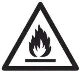
Caution: Risk of fire/flammable materials (Required for R32/R290 units only)
Explanation of symbols displayed on the unit (For the unit adopts R32/R290 Refrigerant only):
 | WARNING | This symbol shows that this appliance used a flammable refrigerant. If the refrigerant is leaked and exposed to an external ignition source, there is a risk of fire. |
 | CAUTION | This symbol shows that the operation manual should be read carefully. |
 | CAUTION | This symbol shows that a service personnel should be handling this equipment with reference to the installation manual. |
 | CAUTION | This symbol shows that information is available such as the operating manual or installation manual. |
- Transport of equipment containing flammable refrigerants See transport regulations
- Marking of equipment using signs See local regulations.
- Disposal of equipment using flammable refrigerants See national regulations.
- Storage of equipment/appliances The storage of equipment should be in accordance with the manufacturer's instructions.
- Storage of packed (unsold) equipment Storage package protection should be constructed such that mechanical damage to the equipment inside the package will not cause a leak of the refrigerant charge. The maximum number of pieces of equipment permitted to be stored together will be determined by local regulations.
6.Information on servicing
1) Checks to the area
Prior to beginning work on systems containing flammable refrigerants, safety checks are necessary to ensure that the risk of ignition is minimised. For repair to the refrigerating system, the following precautions shall be complied with prior to conducting work on the system.
2) Work procedure
Work shall be undertaken under a controlled procedure so as to minimise the risk of a flammable gas or vapour being present while the work is being performed.
3) General work area
All maintenance staff and others working in the local area shall be instructed on the nature of work being carried out. Work in confined spaces shall be avoided. The area around the workspace shall be sectioned off. Ensure that the conditions within the area have been made safe by control of flammable material.
4) Checking for presence of refrigerant
The area shall be checked with an appropriate refrigerant detector prior to and during work, to ensure the technician is aware of potentially flammable atmospheres. Ensure that the leak detection equipment being used is suitable for use with flammable refrigerants, i.e. non-sparking, adequately sealed or intrinsically safe.
5) Presence of fire extinguisher
If any hot work is to be conducted on the refrigeration equipment or any associated parts, appropriate fire extinguishing equipment shall be available to hand. Have a dry powder or CO2 fire extinguisher adjacent to the charging area.
6) No ignition sources
No person carrying out work in relation to a refrigeration system which involves exposing any pipe work that contains or has contained flammable refrigerant shall use any sources of ignition in such a manner that it may lead to the risk of fire or explosion. All possible ignition sources, including cigarette smoking, should be kept sufficiently far away from the site of installation, repairing, removing and disposal, during which flammable refrigerant can possibly be released to the surrounding space. Prior to work taking place, the area around the equipment is to be surveyed to make sure that there are no flammable hazards or ignition risks. No Smoking signs shall be displayed.
7) Ventilated area
Ensure that the area is in the open or that it is adequately ventilated before breaking into the system or conducting any hot work. A degree of ventilation shall continue during the period that the work is carried out. The ventilation should safely disperse any released refrigerant and preferably expel it externally into the atmosphere.
8) Checks to the refrigeration equipment
Where electrical components are being changed, they shall be fit for the purpose and to the correct specification. At all times the manufacturer's maintenance and service guidelines shall be followed. If in doubt consult the manufacturer's technical department for assistance. The following checks shall be applied to installations using flammable refrigerants: The charge size is in accordance with the room size within which the refrigerant containing parts are installed;
The ventilation machinery and outlets are operating adequately and are not obstructed; If an indirect refrigerating circuit is being used, the secondary circuit shall be checked for the presence of refrigerant; Marking to the equipment continues to be visible and legible. Markings and signs that are illegible shall be corrected; Refrigeration pipe or components are installed in a position where they are unlikely to be exposed to any substance which may corrode refrigerant containing components, unless the components are constructed of materials which are inherently resistant to being corroded or are suitably protected against being so corroded.
9) Checks to electrical devices
Repair and maintenance to electrical components shall include initial safety checks and component inspection procedures. If a fault exists that could compromise safety, then no electrical supply shall be connected to the circuit until it is satisfactorily dealt with. If the fault cannot be corrected immediately but it is necessary to continue operation, an adequate temporary solution shall be used. This shall be reported to the owner of the equipment so all parties are advised.
Initial safety checks shall include:
That capacitors are discharged: this shall be done in a safe manner to avoid possibility of sparking; That there no live electrical components and wiring are exposed while charging, recovering or purging the system; That there is continuity of earth bonding.
- Repairs to sealed components
1) During repairs to sealed components, all electrical supplies shall be disconnected from the equipment
being worked upon prior to any removal of sealed covers, etc. If it is absolutely necessary to have an electrical supply to equipment during servicing, then a permanently operating form of leak detection shall be located at the most critical point to warn of a potentially hazardous situation.
2) Particular attention shall be paid to the following to ensure that by working on electrical components, the casing is not altered in such a way that the level of protection is affected. This shall include damage to cables, excessive number of connections, terminals not made to original specification, damage to seals, incorrect fitting of glands, etc. Ensure that apparatus is mounted securely. Ensure that seals or sealing materials have not degraded such that they no longer serve the purpose of preventing the ingress of flammable atmospheres. Replacement parts shall be in accordance with the manufacturer's specifications.
NOTE: The use of silicon sealant may inhibit the effectiveness of some types of leak detection equipment. Intrinsically safe components do not have to be isolated prior to working on them.
- Repair to intrinsically safe components
Do not apply any permanent inductive or capacitance loads to the circuit without ensuring that this will not exceed the permissible voltage and current permitted for the equipment in use. Intrinsically safe components are the only types that can be worked on while live in the presence of a flammable atmosphere. The test apparatus shall be at the correct rating. Replace components only with parts specified by the manufacturer. Other parts may result in the ignition of refrigerant in the atmosphere from a leak.
9.Cabling
Check that cabling will not be subject to wear, corrosion, excessive pressure, vibration, sharp edges or any other adverse environmental effects. The check shall also take into account the effects of aging or continual vibration from sources such as compressors or fans.
- Detection of flammable refrigerants
Under no circumstances shall potential sources of ignition be used in the searching for or detection of refrigerant leaks. A halide torch (or any other detector using a naked flame) shall not be used.
11.Leak detection methods
The following leak detection methods are deemed acceptable for systems containing flammable refrigerants. Electronic leak detectors shall be used to detect flammable refrigerants, but the sensitivity may not be adequate, or may need re-calibration. (Detection equipment shall be calibrated in a refrigerant-free area.) Ensure that the detector is not a potential source of ignition and is suitable for the refrigerant used. Leak detection equipment shall be set at a percentage of the LFL of the refrigerant and shall be calibrated to the refrigerant employed and the appropriate percentage of gas (25 % maximum) is confirmed.
Leak detection fluids
are suitable for use with most refrigerants but the use of detergents containing chlorine shall be avoided as the chlorine may react with the refrigerant and corrode the copper pipe-work. If a leak is suspected, all naked flames shall be removed/extinguished. If a leakage of refrigerant is found which requires brazing, all of the refrigerant shall be recovered from the system, or isolated (by means of shut off valves) in a part of the system remote from the leak. Oxygen free nitrogen (OFN) shall then be purged through the system both before and during the brazing process.
- Removal and evacuation
When breaking into the refrigerant circuit to make repairs or for any other purpose conventional procedures shall be used. However, it is important that best practice is followed since flammability is a consideration. The following procedure shall be adhered to: Remove refrigerant; Purge the circuit with inert gas; Evacuate; Purge again with inert gas; Open the circuit by cutting or brazing.
The refrigerant charge shall be recovered into the correct recovery cylinders. The system shall be flushed with OFN to render the unit safe. This process may need to be repeated several times. Compressed air or oxygen shall not be used for this task. Flushing shall be achieved by breaking the vacuum in the system with OFN and continuing to fill until the working pressure is achieved, then venting to atmosphere, and finally pulling down to a vacuum. This process shall be repeated until no refrigerant is within the system. When the final OFN charge is used, the system shall be vented down to atmospheric pressure to enable work to take place. This operation is absolutely vital if brazing operations on the pipe-work are to take place. Ensure that the outlet for the vacuum pump is not close to any ignition sources and there is ventilation available.
- Charging procedures
In addition to conventional charging procedures, the following requirements shall be followed. Ensure that contamination of different refrigerants does not occur when using charging equipment. Hoses or lines shall be as short as possible to minimise the amount of refrigerant contained in them. Cylinders shall be kept upright.
Ensure that the refrigeration system is earthed prior to charging the system with refrigerant. Label the system when charging is complete (if not already).
Extreme care shall be taken not to overfill the refrigeration system. Prior to recharging the system it shall be pressure tested with OFN. The system shall be leak tested on completion of charging but prior to commissioning. A follow up leak test shall be carried out prior to leaving the site.
- Decommissioning
Before carrying out this procedure, it is essential that the technician is completely familiar with the equipment and all its detail. It is recommended good practice that all refrigerants are recovered safely. Prior to the task being carried out, an oil and refrigerant sample shall be taken in case analysis is required prior to re-use of reclaimed refrigerant. It is essential that electrical power is available before the task is commenced.
a) Become familiar with the equipment and its operation.
b) Isolate system electrically.
c) Before attempting the procedure ensure that: Mechanical handling equipment is available, if required, for handling refrigerant cylinders; All personal protective equipment is available and being used correctly; The recovery process is supervised at all times by a competent person; Recovery equipment and cylinders conform to the appropriate standards.
d) Pump down refrigerant system, if possible.
e) If a vacuum is not possible, make a manifold so that refrigerant can be removed from various parts of the system.
f) Make sure that cylinder is situated on the scales before recovery takes place.
g) Start the recovery machine and operate in accordance with manufacturer's instructions.
h) Do not overfill cylinders. (No more than 80 % volume liquid charge).
i) Do not exceed the maximum working pressure of the cylinder, even temporarily.
j) When the cylinders have been filled correctly and the process completed, make sure that the cylinders and the equipment are removed from site promptly and all isolation valves on the equipment are closed off.
k) Recovered refrigerant shall not be charged into another refrigeration system unless it has been cleaned and checked. cylinders. (No more than 80 % volume liquid charge).
i) Do not exceed the maximum working pressure of the cylinder, even temporarily.
j) When the cylinders have been filled correctly and the process completed, make sure that the cylinders and the equipment are removed from site promptly and all isolation valves on the equipment are closed off.
k) Recovered refrigerant shall not be charged into another refrigeration system unless it has been cleaned and checked.
15. Labelling
Equipment shall be labelled stating that it has been de-commissioned and emptied of refrigerant. The label shall be dated and signed. Ensure that there are labels on the equipment stating the equipment contains flammable refrigerant.
16.Recovery
When removing refrigerant from a system, either for servicing or decommissioning, it is recommended good practice that all refrigerants are removed safely. When transferring refrigerant into cylinders, ensure that only appropriate refrigerant recovery cylinders are employed. Ensure that the correct
number of cylinders for holding the total system charge is available. All cylinders to be used are designated for the recovered refrigerant and labelled for that refrigerant (i.e. special cylinders for the recovery of refrigerant). Cylinders shall be complete with pressure relief valve and associated shut-off valves in good working order. Empty recovery cylinders are evacuated and, if possible, cooled before recovery occurs. The recovery equipment shall be in good working order with a set of instructions concerning the equipment that is at hand and shall be suitable for the recovery of flammable refrigerants. In addition, a set of calibrated weighing scales shall be available and in good working order. Hoses shall be complete with leak-free disconnect couplings and in good condition. Before using the recovery machine, check that it is in satisfactory working order, has been properly maintained and that any associated electrical components are sealed to prevent ignition in the event of a refrigerant release.
Consult manufacturer if in doubt. The recovered refrigerant shall be returned to the refrigerant supplier in the correct recovery cylinder, and the relevant Waste Transfer Note arranged. Do not mix refrigerants in recovery units and especially not in cylinders. If compressors or compressor oils are to be removed, ensure that they have been evacuated to an acceptable level to make certain that flammable refrigerant does not remain within the lubricant. The evacuation process shall be carried out prior to returning the compressor to the suppliers. Only electric heating to the compressor body shall be employed to accelerate this process. When oil is drained from a system, it shall be carried out safely.
Get to know your product
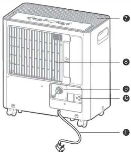
Identification of parts
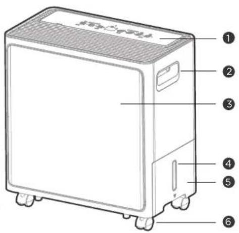
① Control panel
② Handle(both sides)
3 Front panel
4 Water level window
⑤ Water bucket
6 Caster
⑦ Air outlet grille
8 Air filter (Air inlet grille)
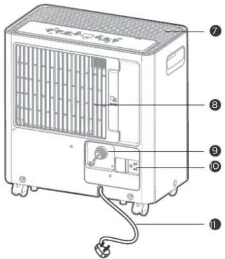
9 Continuous drain hose outlet
10 Power plug storage
11 Power cord and plug

NOTE
All the illustrations in the manual are for explanation purpose only. Your machine may be slightly different. The actual shape shall prevail. The unit can be controlled by the unit control panel.
Positioning the unit
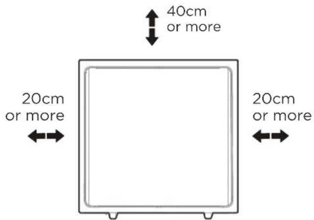
Front view
Top view
Casters(At four points on the bottom of unit)
- Casters can move freely.
- Do not force casters to move over carpet, nor move the unit with water in the bucket. (The unit may tip over and spill water.)
A dehumidifier operating in a basement will have little or no effect in drying an adjacent enclosed storage area, such as a closet, unless there is adequate circulation of air in and out of the area.
- Do not use outdoors.
- This dehumidifer is intended for indoor residential applications only.
This dehumidifer should not be used for commercial or industrial applications.
- Place the dehumidifier on a smooth, level floor strong enough to support the unit with a full bucket of water.
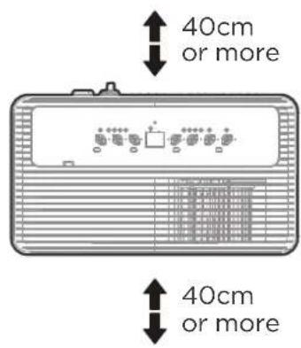
- Allow at least 20cm of air space on all sides of the unit for good air circulation. (at least 40cm of air space on air outlet)
- Place the unit in an area where the temperature will not fall below 5^ C(41° F). The coils can become covered with frost at temperatures below 5^ C(41° F), which may reduce performance.
- Place the unit away from the clothes dryer, heater or radiator.
- Use the unit to prevent moisture damage anywhere books or valuables are stored.
- Use the dehumidifier in a basement to help prevent moisture damage.
- The dehumidifier must be operated in an enclosed area to be most effective.
- Before all tilting and moving operations, take out the bucket, open the continuous drain outlet to empty the water, and disconnect the power cord.
When using your product

NOTE
When the water in the bucket reaches to a certain level, please be careful to move the machine to avoid it falling down.
flowchart
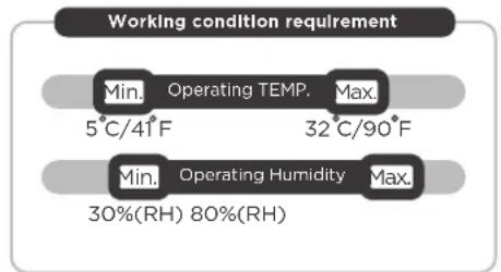
graph TD
    A["Working condition requirement"] --> B["Min. Operating TEMP. 5°C/41°F"]
    A --> C["Max. 32°C/90°F"]
    B --> D["Min. Operating Humidity 30%(RH) 80%(RH)"]
    C --> E["Max. 80%(RH)"]
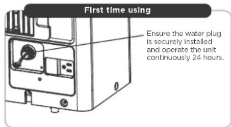
- When first using the dehumidifier, operate the unit continuously 24 hours. Ensure that the plastic cover is securely installed in continuous dehumidification mode and does not leak.
- This unit is designed to operate with a working environment between 5 °C/41 °F and 32 °C/90 °F, and between 30%(RH) and 80%(RH).
- When use in open space with open windows, condensation may form on the surface of the product, which is normal.
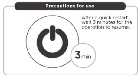
- If the unit has been switched off and needs to be switched on again quickly, allow approximately three minutes for the correct operation to resume.
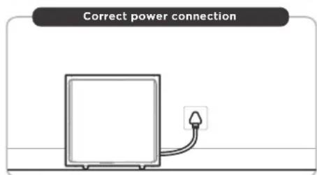
- Do not connect the dehumidifier to a multiple socket outlet, which is also being used for other electrical appliances.
- Select a suitable location, making sure you have easy access to an electrical outlet.
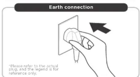
- Plug the unit into a electrical socket-outlet with earth connection.
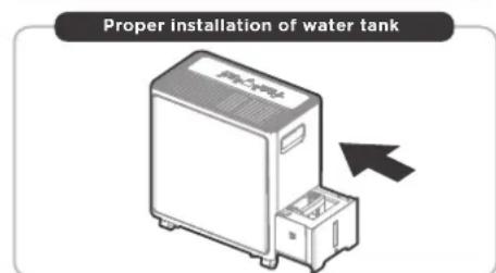
• Make sure the Water bucket is correctly fitted otherwise the unit will not operate properly.
Accessories
Optional accessories
Drain Hose (1 pc ^* )
NOTE: Make the water pipe straight when you use it
Get to know your features
Control Panel Features

NOTE
The following control panels are for explanation purpose only. The control panel of the unit you purchased may be slightly different according to the models. Your machine may not contain some indicators or buttons. The actual shape shall prevail.

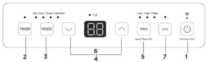
1. POWER ON/OFF button
Press to turn the dehumidifier on and off.
- Press and hold on the POWER button for 3 seconds to initiate the Wireless connection mode.
The LED DISPLAY shows'AP' to indicate you can set Wireless connection and the wireless indicator light flashes. - If connection (router) is successful within 8 minutes, the unit will exit Wireless connection mode automatically and the Wireless indicator illuminates and the unit enters the previous function.
If connection is failure within 8 minutes, the unit exits the Wireless connection mode automatically
2. TIMER Function
Press the button to initiate the Auto start and Auto stop function, in conjunction with the UP and DOWN buttons.
Auto start setting
- In the shutdown state, press the button to active the Auto start time.
- Press or hold the UP or DOWN button to change the Auto start time by 0.5 hour increments, up to 10 hours, then at 1 hour increments, up to 24 hours.
- The selected time will register in 5 seconds and the system will automatically revert back to display the humidity. The control will count down the time remaining until start.
Auto stop setting
- In the startup state, press the button to active the Auto stop time.
- Press or hold the UP or DOWN button to change the Auto stop time by 0.5 hour increments, up to 10 hours, then at 1 hour increments, up to 24 hours.
- The selected time will register in 5 seconds and the system will automatically revert back to display the humidity. The control will count down the time remaining until stop.
NOTE: The timing can be adjusted to increase or decrease by 24 hours. After the TIMER setting is complete, you can press the button again to check the TIMER setting status. After the TIMER setting is complete, you can cancel it by setting the set time to 0.0.
3. MODE Function
Press the button to select the mode you want, as shown: Set→Cont.→Dryer→Comfort.
NOTE: Dryer and Comfort are optional; The humidity setting cannot be adjusted in Dryer, Cont. and Comfort; The set humidity will be displayed when the mode is set to Set, and the ambient humidity will be displayed 5 seconds later.
Set Dehumidifying mode(Set)
Press the button to select the Dehumidifying mode, and adjust the desired humidity by pressing the UP and DOWN buttons.
NOTE: Humidity can be set from 35% to 85%, with 5% adjustment perpress.
Continuous dehumidifying mode(Cont.)
Press the button to select the Continuous dehumidifying mode.
NOTE: Humidity cannot be adjusted in this mode.
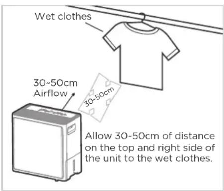
Dryer mode (Dryer)
Press the button to select the Dryer mode, and the unit will operate in Continuous dehumidifying and High fan speed mode, in this mode.
- Close doors and Windows while operating in this mode.
- To make the best effective dehumidification, please dehydrate the wet clothes at first.
- Make sure to direct airflow at the wet clothes.
- For thick and heavy wet clothes may not get the best effective dehumidification.
Smart dehumidifying mode (Comfort)
Press the button to select the Smart dehumidifying mode.
NOTE: Humidity cannot be adjusted in this mode. The unit will automatically control room humidity in a comfortable range 45%\~55% according to the room temperature.
4. UP and DOWN buttons
Humidity Set Control buttons
The humidity level can be set within a range of 35% RH(Relative Humidity) to 85%RH(Relative Humidity) in 5% increments.
TIMER Set Control buttons
Press the UP and DOWN buttons to set the Auto start and Auto stop time from 00:00 to 24:00.
5. FAN speed Function
Press the button to select fan speed in the following setting: Low → High → Low...
NOTE: The fan speed indicator light illuminates under different fan speed settings.
6. Display
Display ambient humidity and setting humidity (humidity range: 30% to 90%); Display TIMER setting (timing range: 24 hours); Display error codes reminder.
Error Codes:
- EH61 - Evaporator coil temperature sensor error. Unplug the unit and plug it back in. If the error repeats, call for service.
- EH60 - Room temperature sensor error. Unplug the unit and plug it back in. If the error repeats, call for service.
- P2 - Bucket is full of water or bucket is not in right position. Empty the bucket and replace it in the right position.
- EH00 - Indoor EEPROM error. Unplug the unit and plug it back in. If error repeats, call for service.
7. ION Function - optional
In the startup state, press the button to enable/disable the ION function.
More Features
Auto Shut Off
The dehumidifier shuts off when the bucket is full, or when the bucket is removed or not replaced in the proper position. For some models, the fan motor will continue to run for 30 seconds. When the Full indicator light illuminates, please empty the bucket and reinstall it correctly. and the other problems are to install the bucket correctly. Then, wait 3 minutes before resuming operation, it can not be restart operation in the first 3 minutes. This is to protect the unit. Operation will automatically start after 3 minutes.
Check filter feature
The system starts to count the time once the fan motor operates. The check filter feature can be only activated when the accumulated operation time achieves 250 hours or more. The Reset light (Clean filter indicator light) flashes at one time per second, after finishing clean the air filter, press the FAN (reset filter) button for 3 seconds and the Reset light(Clean filter indicator light) goes off.
Auto-Restart
If the unit breaks off unexpectedly due to the power cut, it will restart with the previous function setting automatically when the power resumes.
Dump the collected water
There are two ways to remove collected water.
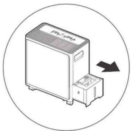
Type 1:
Bucket drainage
natural_image
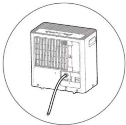
Line drawing of a portable air conditioner unit with a cable inserted, enclosed in a circle (no text or symbols)Type 2:
water hose drainage
(continuous)
Bucket drainage
Type 1
- When the unit is off, if the bucket is full, the Full indicator light will light.
- When the unit is on, if the bucket is full, the compressor and the fan turn off, and the Full indicator light will light, the digital display shows P2.
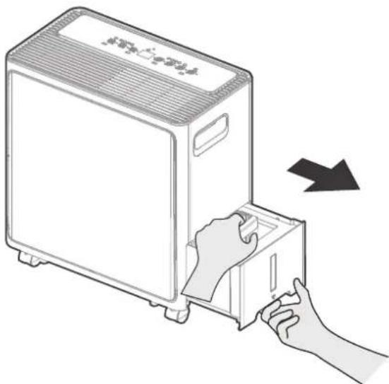
- Pull the bucket out halfway, then pull up the handle and lift the bucket slowly vertically to prevent spatter.
- Throw away the water and replace the bucket. The bucket must be in right place and securely seated for the dehumidifier to operate.
- The appliance will re-start when the bucket is restored in its correct position.
1 Pull the bucket out halfway.
natural_image
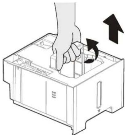
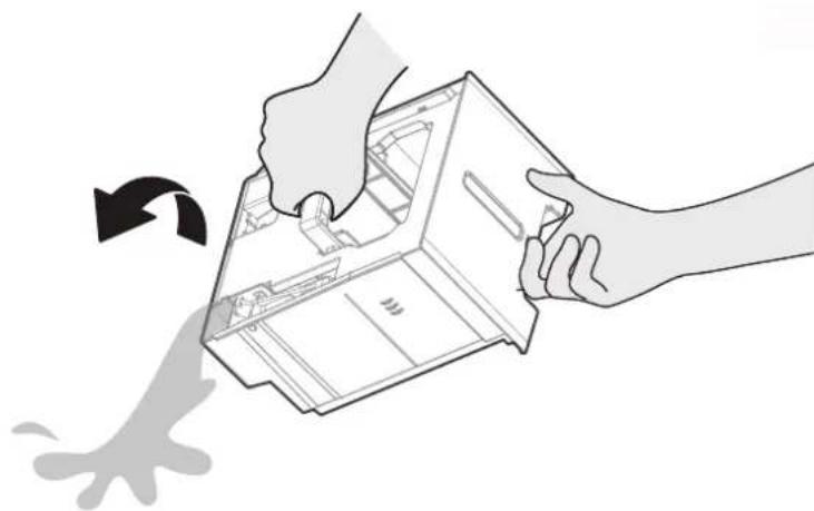
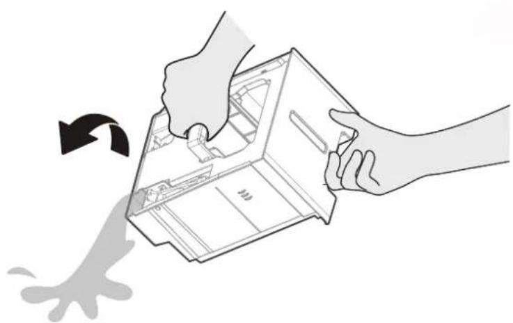
Illustration of hands installing or adjusting a device into a container (no text or symbols visible)2 Pull up the handle and lift the bucket slowly vertically.
natural_image
Illustration of a hand inserting into a device into a plastic housing, with an arrow indicating rotation (no text or symbols)3 Pour the water out.
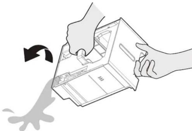
natural_image
Illustration of hands installing or removing a mechanical component with a curved arrow indicating motion (no text or symbols)
WARNING:
Do not pull out the whole bucket, or it may cause damage to the bucket or even injure you.

NOTE
- When you remove the bucket, do not touch any parts inside of the unit. Doing so may damage the product. Be sure to push the bucket gently all the way into the unit. Banging the bucket against anything or failing to push it in securely may cause the unit not to operate.
- When you remove the bucket, if there is some water in the unit you must dry it.
- When the unit is on, if the bucket is removed, the compressor and the fan turn off, then the unit will beep 8 times and the digital display shows Eb.
- When the unit is off, if the bucket is removed, the unit will beep 8 times and the digital display shows Eb.
Water can be automatically emptied into a floor drain by attaching the unit with a water hose(Id ≥ Φ5/16", not included) with a female threaded end(ID:M=1",not included)
Note: On some models, the female threaded end is include.
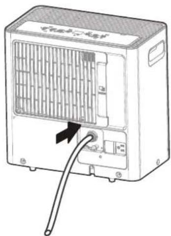
Remove the water plug from the back drain outlet of the unit and set aside, then insert the drain hose through the drain outlet of the unit and lead the drain hose to the floor drain or a suitable drainage facility.
1 Remove the water plug.
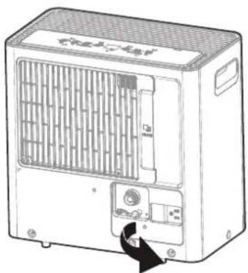
natural_image
Line drawing of a portable air conditioner unit with ventilation grilles and control panel (no text or symbols)2 Connect the drain hose.
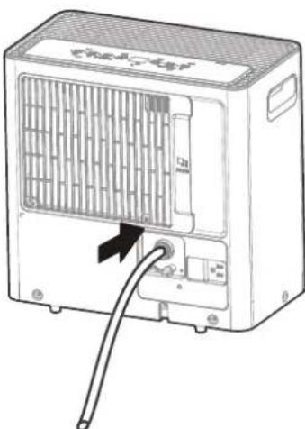
natural_image
Line drawing of a portable air conditioner unit with ventilation grille and cable (no text or symbols)- When you remove the plastic cover, if there is some water in the back drain outlet of the unit you must dry it. Make sure the hose is secure so there are no leaks and the end of the hose is level or down to let the water flow smoothly.
- Direct the hose toward the drain, making sure that there are no kinks that will stop the water flowing. Make sure the water hose is lower than the drain hose outlet of the unit.
- Select the desired humidity setting and fan speed on the unit for continuous draining to start.
NOTE: When the continuous draining feature is not being used, remove the drain hose from the outlet, and dry the water in the continuous drain hose outlet.
Care and Maintenance
Care and cleaning of the dehumidifier Turn the dehumidifier off and remove the plug from the wall outlet before cleaning.
Clean the Grille and Case
- Use water and a mild detergent. Do not use bleach or abrasives.
- Do not splash water directly onto the main unit. Doing so may cause an electrical shock, cause the insulation to deteriorate, or cause the unit to rust.
• The air intake and outlet grilles get soiled easily, so use a vacuum attachment or brush to clean.
Clean the bucket
• Every few weeks, clean the bucket to prevent growth of mold, mildew and bacteria.
Partially fill the bucket with clean water and add a little mild detergent. Swish it around in the bucket, empty and rinse.
Note: Do not use a dishwasher to clean the bucket. After clean, the bucket must be in place and securely seated for the dehumidifier to operate.
Clean the air filter
-
Remove the filter every two weeks based on normal operating conditions.
• To remove the filter, pull filter outwards. -
Wash the filter with clean water then dry.
• Re-install the filter, replace Bucket.
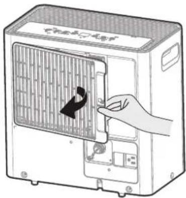
natural_image
Illustration of a hand inserting a component into a device with a black arrow indicating the component (no text or symbols present)When not using the unit for long time periods
Refer to Care and Maintenance for instruction on steps 4-6.
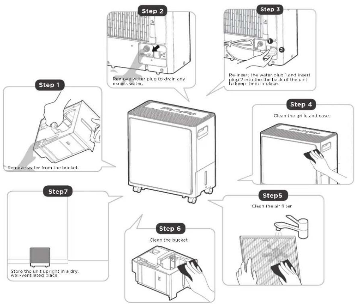
flowchart
graph TD
    A["Step 1: Remove water from the bucket"] --> B["Step 2: Remove water plug to drain any excess water."]
    B --> C["Step 3: Re-insert the water plug 1 and insert plug 2 into the back of the unit to keep them in place."]
    C --> D["Step 4: Clean the grille and case."]
    D --> E["Step 5: Clean the air filter"]
    E --> F["Step 6: Clean the bucket"]
    F --> G["Step 7: Store the unit upright in a dry, well-ventilated place."]
- After turning off the unit, wait one day before emptying the bucket to collect any condensate that may continue to form after use.
- Clean the main unit, water bucket and air filter.
- Please dry off any excess water that may be present after removing the bucket.
- Wrap the cord with the power cord buckle.
• Properly restore the bucket and place the unit in an upright position.
• Cover the unit with a plastic bag. - Store the unit upright in a dry, well-ventilated place.
Troubleshooting
| Problem What to check | |
| Unit does not start | Make sure the dehumidifier s plug is pushed completely into the outlet.Check the house fuse/circuit breaker box.Dehumidifier has reached its preset level or bucket is full.Water bucket is not in the proper position. |
| Dehumidifier does not dry the air as it should | Do not allow enough time to remove the moisture.Make sure there are no curtains, blinds or furniture blocking the front or back of the dehumidifier.The humidity control may not be set low enough.Check that all doors, windows and other openings are securely closed.Room temperature is too low , below 5°C(41°F).There is a kerosene heater or something giving off water vapor in the room. |
| The unit makes a loud noise when operating | The air filter is clogged.The unit is tilted instead of upright as it should be.The floor surface is not level. |
| Frost appears on the coils | This is normal. The dehumidifier has Auto defrost feature. |
| Water on floor | Hose to connector or hose connection may be loose.Intend to use the bucket to collect water, but the back drain plug is removed. |
| EH00,EH60,EH61,P2 appear in the display | These are error codes and protection codes.See the CONTROL PANEL FEATURES section. |
The design and specifications are subject to change without prior notice for product improvement. Consult with the sales agency or manufacturer for details. Any updates to the manual will be uploaded to the service website, please check for the latest version.
Disposal and Recycling
Important instructions for environment(European Disposal Guidelines)
Compliance with the WEEE Directive and Disposing of the Waster Product: This product complies with EU WEEE Directive. This product bears a classification symbol for waster electrical and electronic equipment (WEEE).
This symbol indicates that this product shall not be disposed with other household wastes at the end of its service life. Used device must be returned to official collection point for recycling of electrical electronic devices. To find these collection systems please contact to your local authorities or retailer where the product was purchased. Each household performs important role in recovering and recycling of old appliance. Appropriate disposal of used appliance helps prevent potential negative consequences for the environment and human health.
natural_image
Symbol of a trash bin crossed with two crossed lines, representing no waste or restriction (no text present)The design and specifications are subject to change without prior notice for product improvement. Consult with the sales agency or manufacturer for details. Any updates to the manual will be uploaded to the service website, please check for the latest version.
CD002UI-DA
16120100A22155
USER MANUAL OF SMART KIT

SmartHome

Download the app & activate product
IMPORTANT NOTE:
Read the manual carefully before installing or connecting your dehumidifier. Make sure to save this manual for future reference.
CONTENTS
1 SPECIFICATION 1
2 PRECAUTIONS 1
3 USING THE SMARTHOME APP 2
4 COMPLIANCE 6
1 SPECIFICATION
Unit model:MDDA-30DEN7-SD
Wireless Module Model: EU-SK105, US-SK105, EU-SK106, US-SK106,
EU-SK107, US-SK107, EU-SK109, US-SK109, EU-SK110, US-SK110
Antenna Type: Printed PCB Antenna
Frequency Band: 2400-2483.5MHz
Operation Temperature: 0^ 45^ C / 32^ 113^ F
Operation Humidity: 10% \~ 85%
Power Input: DC 5V / 500mA
Maximum TX Power: < 20dBm
2 PRECAUTIONS
- App Compatibility:
- The app is available for both iOS and Android, however older versions may no longer be compatible. Please keep the app updated with the latest version. Midea makes no guarantee of compatibility and is not responsible for issues arising as a consequence thereof.
- The app is subject to updates without prior notice for product function improvement.
- Wireless Security:
- The Smart Kit supports the following security protocols: WPA-PSK / WPA2-PSK / WPA3-SAE.
- It may be used with or without encryption although encryption is strongly recommended.
- Connectivity:
- Network issues may occasionally cause timeouts. The unit display and the app may become unsynchronized but this will resolve itself when the network is restored.
- Should the network remain unavailable, it might be necessary to run the configuration process again.
- Change in the wireless network will require reconfiguration of the device.
- Configuration:
- The actual network configuration process may vary slightly from the manual.
- Please check the service website for more information.
- Restore to factory settings:
- When the user deletes the device on the APP, the module automatically restores to the factory settings.
3 USING THE SMARTHOME APP
⚠ Ensure that your mobile phone is connected to the wireless network. Bluetooth must be turned on. The device must also be powered up.
■ Step 1: Download the SmartHome app
Scan the QR code below to download the SmartHome app from app store or search for it directly on the Google Play Store or Apple's App Store.

■ Step 2: Log in
Open the SmartHome app. Log in directly if you have an existing SmartHome account or create a new account. Alternatively, you can also use a 3rd party login platform.

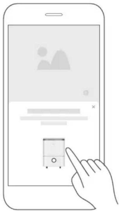
■ Step 3: Connecting the device
1) When you log in, you may see the message "Smart devices discovered nearby". Tap to add your device.
natural_image
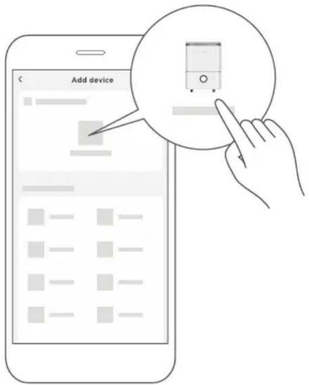
Illustration of a hand interacting with a smartphone displaying a small device interface (no text or symbols visible)2) If no such message appears, proceed as follows:
Tap on "+" and select your device in the list of nearby available devices. If your device is not listed, please add your device manually, first selecting the device category e.g. Dehumidifier.
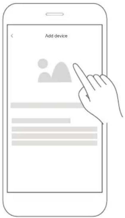
3) Follow the steps in the app to connect your device to the wireless network. If your device fails to connect, follow the additional instructions in the app.
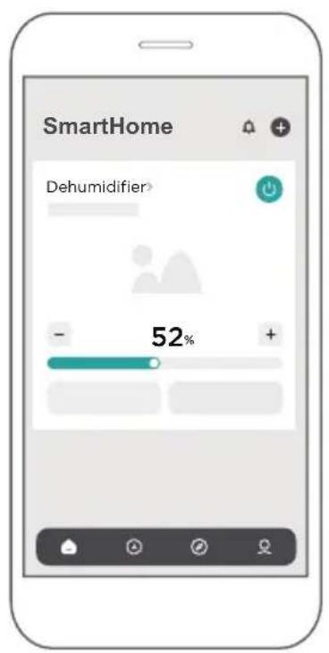
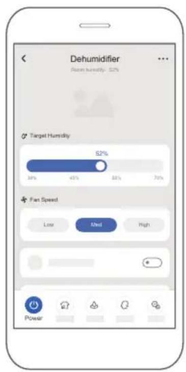
■ Step 4: Controlling the device
After pairing successfully, a card will be created for the device in the SmartHome app.
Shortcuts for basic functions will appear on the card such as changing the humidity or switching the device on or off.
Tapping on the card, will reveal additional features and settings. The actual UI design may look different from examples due to app updates.
4 COMPLIANCE
We, hereby declare that this device is in compliance with the relevant provisions of RE Directive 2014/53/EU. A copy of the full DoC is attached (Europen Union products only).
Wireless module models:
This device complies with Part 15 of the FCC Rules and it contains licence exempt transmitter(s)/receiver(s) that comply with Innovation, Science and Economic Development Canada's licence-exempt RSS(s).
Operation is subject to the following two conditions:
(1) This device may not cause harmful interference;
(2) This device must accept any interference, including interference that may cause undesired operation of the device.
Only operate the device in accordance with the instructions supplied.
Changes or modifications to this unit not expressly approved by the party responsible for compliance could void the user's authority to operate the equipment.
This device complies with FCC radiation exposure limits set forth for an uncontrolled environment. In order to avoid the possibility of exceeding the FCC radio frequency exposure limits, human proximity to the antenna shall not be less than 20cm (8 inches) during normal operation.
In Canada:
CAN ICES-3(B)/NMB-3(B)
NOTE: This equipment has been tested and found to comply with the limits for a Class B digital device, pursuant to part 15 of the FCC Rules. These limits are designed to provide reasonable protection against harmful interference in a residential installation.
This equipment generates, uses and can radiate radio frequency energy and, if not installed and used in accordance with the instructions, may cause harmful interference to radio communications.
However, there is no guarantee that interference will not occur in a particular installation. If this equipment does cause harmful interference to radio or television reception, which can be determined by turning the equipment off and on, the user is encouraged to try to correct the interference by one or more of the following measures:
--Reorient or relocate the receiving antenna.
--Increase the separation between the equipment and receiver.
--Connect the equipment into an outlet on a circuit different from that to which the receiver is connected.
--Consult the dealer or an experienced radio/TV technician for help.
Importer: Midea Europe GmbH Ludwig-Erhard-Str. 14 65760 Eschborn Germany
Manufacturer:
GD Midea Air-Conditioning Equipment Co., Ltd.
Lingang Road Beijiao Shunde Foshan
Guangdong People's Republic of China 528311
Company will not be liable for any issues and problems caused by Internet, Wireless Router and Smart Devices. Please contact the original provider to get further help.
CS381-APP(Smarthome-Dehumidify)
16120100A22155
Comfee'

natural_image
Line drawing of a portable air purifier with wheels and ventilation slots (no text or symbols)LUFTENTFEUCHTER
BENUTZERHANDBUCH
MODELL-NR: MDDA-30DEN7-SD

Vorsicht:

natural_image
Illustration of a portable electronic device with a paper box and a circular arrow indicating direction (no text or symbols)natural_image
Line drawing of a portable air conditioner unit with attached cable, enclosed in a circle (no text or symbols)natural_image
Illustration of hands installing or adjusting a device into a container (no text or symbols visible)natural_image
Illustration of a hand inserting into a device into a container with an arrow indicating rotation (no text or symbols)natural_image
Illustration of hands installing or adjusting a mechanical component with a curved arrow indicating motion (no text or symbols present)
WARNUNG:
natural_image
Line drawing of a computer unit with ventilation grilles and buttons (no text or symbols)natural_image
Symbol of a trash bin crossed out by two crossed lines, with a solid black rectangle below (no text or labels)natural_image
Illustration of a hand interacting with a smartphone displaying a small device (no text or symbols visible)4 KONFORMITÄT
GD Midea Air-Conditioning Equipment Co., Ltd.
Lingang Road, Beijiao, Shunde, Foshan
Guangdong, V.R. China 528311
natural_image
Line drawing of a portable air purifier with wheels and ventilation slots (no text or symbols)DÉSHUMIDIFICATEUR
MANUEL D'UTILISATION
NUMÉRO DE MODÈLE
MDDA-30DEN7-SD

natural_image
Illustration of a portable electronic device with a black arrow pointing to its side panel (no text or symbols present)natural_image
Illustration of a server unit with a circular arrow indicating direction (no text or symbols)natural_image
Line drawing of a portable air conditioner unit with a cable inserted, enclosed in a circle (no text or symbols)natural_image
Illustration of a hand inserting into a device into a container with an arrow indicating rotation (no text or symbols)natural_image
Illustration of hands exchanging a device with a scroll, showing internal components and motion (no text or symbols)
AVERTISSEMENT :
natural_image
Line drawing of a computer unit with ventilation grilles and control panel (no text or symbols)natural_image
Line drawing of a portable electronic device with ventilation grille and cable (no text or symbols)natural_image
Illustration of a hand inserting a device into a computer unit (no text or symbols visible)natural_image
Symbol of a trash bin crossed with no text or labels, accompanied by a solid black rectangle below (no text or symbols present)natural_image
Illustration of a hand interacting with a smartphone displaying a small device interface (no text or symbols visible)4 CONFORMITÉ
GD Midea Air-Conditioning Equipment Co., Ltd.
Lingang Road Beijiao Shunde Foshan
CS381-APPLICATION (Smarthome-
Déshumidifier)
16120100A22155
Comfee'
natural_image
Line drawing of a portable air purifier with wheels and ventilation slots (no text or symbols)DEUMIDIFICATORE
MANUALE DELL'UTENTE
NUMERO MODELLO
MDDA-30DEN7-SD

Attenzione:
natural_image
Illustration of a portable electronic device with a box and arrow indicating direction (no text or symbols)natural_image
Line drawing of a portable air conditioner unit with ventilation slots and a cable, enclosed in a circle (no text or symbols)natural_image
Illustration of hands installing or adjusting a device into a container (no text or symbols visible)natural_image
Illustration of a hand inserting into a device into a container with an arrow indicating rotation (no text or symbols)3 Versare l'acqua.
natural_image
Illustration of hands exchanging a device with a scroll, showing internal components and motion (no text or symbols)
AVVERTENZA:
natural_image
Line drawing of a computer air conditioner unit with ventilation grilles and control panel (no text or symbols)natural_image
Line drawing of a portable air conditioner unit with a cable inserted, showing internal fan and socket (no text or symbols)natural_image
Symbol of a trash bin crossed with a diagonal line and a horizontal bar below (no text or labels)MANUALE UTENTE DELLO SMART KIT

SmartHome

natural_image
Illustration of a hand interacting with a smartphone displaying a small device interface (no text or symbols visible)4 CONFORMITÀ
GD Midea Air-Conditioning Equipment Co., Ltd.
Lingang Road Beijiao Shunde Foshan
natural_image
Line drawing of a portable air purifier with wheels and ventilation slots (no text or symbols)DESHUMIDIFICADOR
MANUAL DE USUARIO
NÚMERO DE MODELO: MDDA-30DEN7-SD

Precaución:
natural_image
Illustration of a portable electronic device with a box and arrow indicating direction (no text or symbols)natural_image
Illustration of a portable electronic device with a box and fan, enclosed in a circle (no text or symbols)natural_image
Line drawing of a portable air conditioner unit with a cable inserted, enclosed in a circle (no text or symbols)natural_image
Illustration of hands installing or adjusting a device into a container (no text or symbols visible)natural_image
Illustration of a hand inserting into a device into a plastic housing, with arrows indicating rotation (no text or symbols)3 Vierta el agua.
natural_image
Illustration of hands installing or adjusting a mechanical component with a curved arrow indicating motion (no text or symbols)
ADVERTENCIA:
natural_image
Line drawing of a computer unit with ventilation grilles and a scroll wheel (no text or symbols)2 Conecte la manguera de desagüe.
natural_image
Line drawing of a portable air conditioner unit with a cable inserted, showing internal fan structure and power outlet (no text or symbols)natural_image
Symbol of a trash bin crossed with no text or numbers, representing waste sorting or restriction (no text present)natural_image
Illustration of a hand interacting with a smartphone displaying a small device interface (no text or symbols visible)4 CONFORMIDAD
GD Midea Air-Conditioning Equipment Co., Ltd.
Lingang Road Beijiao Shunde Foshan
Guangdong, República Popular China, 528311
EU DECLARATION OF CONFORMITY
(In accordance with EN ISO/IEC 17050-1)
| Declaration number: | No.2024092301 | |
| Name and address of manufacturer / EU-AR: | MIDEA EUROPE GMBHLudwig-Erhard-Straße 14 65760 Eschborn Germany |  |
| THIS DECLARATION OF CONFORMITY IS ISSUED UNDER THE SOLE RESPONSIBILITY OF: | ||
| Name and address of manufacturer: | MIDEA EUROPE GMBHLudwig-Erhard-Straße 14 65760 Eschborn Germany | |
| Product identification: | DEHUMIDIFIERMDDA-30DEN7-SD | |
| THE PRODUCTS MENTIONED IN THIS DECLARATION ARE IN CONFORMITY WITH: | ||
| EU Community Legislation: | Restriction of Hazardous Substances (RoHS) Directive 2011/65/EU [OJEU L174/8 110, 01.07.2011] | |
| Radio Equipment Directive (RED) 2014/53/EU [OJEU L153/62-106,22.05.2014] | ||
| Harmonised standards: | Radio equipmentEN 300 328 V2.2.2:2019 | |
| Safety of electrical equipmentEN 60335-2-40:2003 + AC:2006 + A11:2004 +A12:2005+ A1:2006 + A2:2009 + A13: + A13:2012/AC:2013EN 60335-1:2012+ AC:2014+A11:2014 +A13:2017 + A1:2019 + A14:2019 + A2:2019 A15:2021Exposure of humans to electromagnetic fields (EMF)EN 62233:2008 + AC:2008EN IEC 62311:2020Electromagnetic Compatibility (EMC)EN 301 489-17 V3.2.4:2020EN 301 489-1 V2.2.3:2019EN IEC 55014-1:2021, EN 55014-1:2017/A11:2020EN IEC 55014-2: 2021, EN 55014-2: 2015EN IEC 61000-3-2:2019, EN IEC 61000-3-2:2019/A1:2021EN 61000-3-3:2013/A1:2019 | ||
| Additional information: | Supplied accessories and components : Smart Kit (Wireless and Bluetooth)Software: 150029092122 010008.bin | |
| SIGNED FOR AND ON BEHALF OF: | ||
| Place and date of issue: | Eschborn, 2024/09/23 | |
| Signature: | Lucas Ye | |
| Name, position: | Lucas Ye | Product Manager |
| Company name: | MIDEA EUROPE GMBH | |
RED Declaration of Conformity (DoC)
Unique identification of this DoC: No2024092402
We,
MIDEA EUROPE GMBH
Ludwig-Erhard-Straße 14 65760 Eschborn Germany
declare under our sole responsibility that the product:
product name: DEHUMIDIFIER
trade name: COMFEE
type or model: MDDA-30DEN7-SD
relevant supplementary information: ....
(e.g. lot, batch or serial number, sources and numbers of items)
to which this declaration relates is in conformity with the essential requirements an other relevant requirements of the RE Directive (2014/53/EU).
The product is in conformity with the following standards and/or other normative documents:
HEALTH & SAFETY (Art. 3(1)(a)): EN 62311:2008, EN IEC 62311:2020, EN 60335-2-40:2003/A13:2012, EN 60335-1:2012/A16:2023, EN 62233:2008; EN 62479:2010; EN 5066
EMC (Art. 3(1)(b)): EN 301 489-1 V2.2.3: 2019, EN 301 489-17 V3.2.4 :2020, EN 1:2021, EN IEC 55014-2:2021, EN IEC 61000-3-2:2019/A1:2021, EN 61000-3-3:2013/A2:20
SPECTRUM (Art. 3(2)): EN 300 328 V2.2.2 (2019-07)
OTHER (incl. Art. 3(3) and voluntary specs): ....
(title and/or number and date of issue of the standard(s) or other normative document(s))
Limitation of validity (if any): ....
Supplementary information:
Notified body involved: TUV SUD Product Service......
Software: 150029092122 010008.bin
Technical file held by: GD Midea Air-Conditioning Equipment Co., Ltd.....
Place and date of issue (of this DoC): Eschborn, 2024/09
Signed by or for the manufacturer: ....
(Signature of authorised person)
Name (in print): ....LUCAS YE....
Title: .....Product manager.....

- USER MANUAL
- CONTENTS
- Safety Precautions
- Explanation of Symbols
- WARNING
- CAUTION
- Note about Fluorinated Gasses(Not applicable to the unit using R290 Refrigerant)
- WARNING for Using R290/R32 Refrigerant
- For R32
- Caution: Risk of fire/flammable materials (Required for R32/R290 units only)
- Labelling
- 16.Recovery
- Get to know your product
- Identification of parts
- NOTE
- Positioning the unit
- When using your product
- Accessories
- Optional accessories
- Get to know your features
- Control Panel Features
- POWER ON/OFF button
- TIMER Function
- Auto start setting
- Auto stop setting
- MODE Function
- Set Dehumidifying mode(Set)
- Continuous dehumidifying mode(Cont.)
- Dryer mode (Dryer)
- Smart dehumidifying mode (Comfort)
- UP and DOWN buttons
- Humidity Set Control buttons
- TIMER Set Control buttons
- FAN speed Function
- Display
- Error Codes:
- ION Function - optional
- More Features
- Auto Shut Off
- Check filter feature
- Auto-Restart
- Dump the collected water
- Bucket drainage
- Type 1
- Pull the bucket out halfway.
- Pull up the handle and lift the bucket slowly vertically.
- Pour the water out.
- WARNING:
- Remove the water plug.
- Connect the drain hose.
- Care and Maintenance
- Clean the Grille and Case
- Clean the bucket
- Clean the air filter
- When not using the unit for long time periods
- Troubleshooting
- Disposal and Recycling
- Important instructions for environment(European Disposal Guidelines)
- USER MANUAL OF SMART KIT
- IMPORTANT NOTE:
- SPECIFICATION
- PRECAUTIONS
- - App Compatibility:
- - Wireless Security:
- - Connectivity:
- - Configuration:
- - Restore to factory settings:
- USING THE SMARTHOME APP
- ■ Step 1: Download the SmartHome app
- ■ Step 2: Log in
- ■ Step 3: Connecting the device
- ■ Step 4: Controlling the device
- COMPLIANCE
- Wireless module models:
- In Canada:
- Importer: Midea Europe GmbH Ludwig-Erhard-Str. 14 65760 Eschborn Germany
- Manufacturer:
- Comfee'
- BENUTZERHANDBUCH
- Vorsicht:
- WARNUNG:
- KONFORMITÄT
- MANUEL D'UTILISATION
- AVERTISSEMENT :
- CONFORMITÉ
- MANUALE DELL'UTENTE
- Attenzione:
- Versare l'acqua.
- AVVERTENZA:
- MANUALE UTENTE DELLO SMART KIT
- CONFORMITÀ
- MANUAL DE USUARIO
- Precaución:
- Vierta el agua.
- ADVERTENCIA:
- Conecte la manguera de desagüe.
- CONFORMIDAD
- EU DECLARATION OF CONFORMITY
- RED Declaration of Conformity (DoC)
Brand : COMFEE
Model : MDDA-30DEN7-SD
Category : Dehumidifier