Laminar Jets - Pump Jandy - Free user manual and instructions
Find the device manual for free Laminar Jets Jandy in PDF.
User questions about Laminar Jets Jandy
0 question about this device. Answer the ones you know or ask your own.
Ask a new question about this device
Download the instructions for your Pump in PDF format for free! Find your manual Laminar Jets - Jandy and take your electronic device back in hand. On this page are published all the documents necessary for the use of your device. Laminar Jets by Jandy.
USER MANUAL Laminar Jets Jandy
natural_image
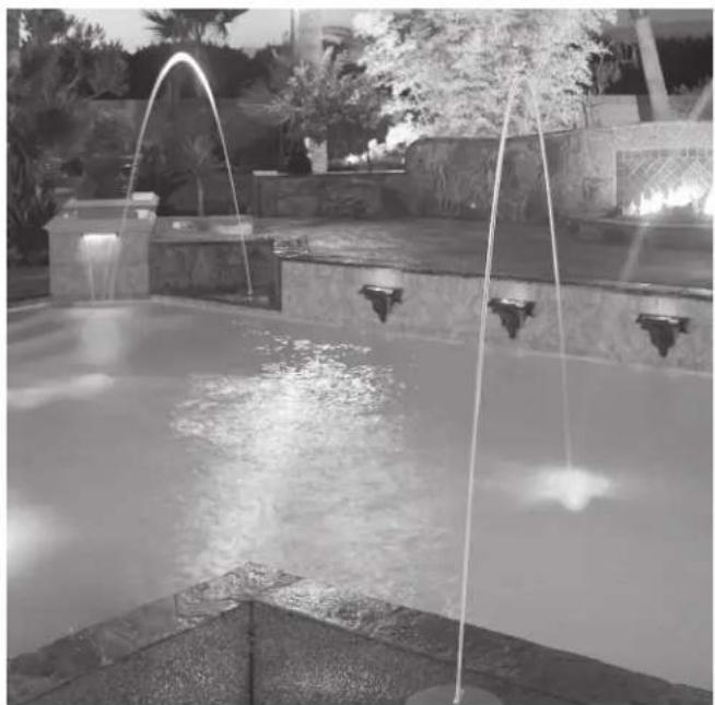
Black-and-white photo of a fountain with water jets and decorative plants in the background (no visible text or symbols)Jandy Laminar Jet
JLLED4C Series
JLFBR Series
WARNING
FOR YOUR SAFETY - This product must be installed and serviced by a contractor who is licensed and qualified in pool equipment by the jurisdiction in which the product will be installed where such state or local requirements exist. The maintainer must be a professional with sufficient experience in pool equipment installation and maintenance so that all of the instructions in this manual can be followed exactly. Before installing this product, read and follow all warning notices and instructions that accompany this product. Failure to follow warning notices and instructions may result in property damage, personal injury, or death. Improper installation and/or operation may void the warranty.

DO NOT MODIFY THIS EQUIPMENT.
Improper installation and/or operation can create unwanted electrical hazard which can cause serious injury, property damage, or death.
ATTENTION INSTALLER - This manual contains important information about the installation, operation and safe use of this product. This information should be given to the owner/operator of this equipment.
Table of Contents
Section 1. Safety Information....3
Section 2. General Installation Requirements....5
2.1 Water Source....5
2.2 Pump 5
2.3 Plumbing 5
2.4 LED Light Module....5
2.5 Conduit/Fiber Optics Module....5
2.6 Critical Placement Dimensions....5
Section 3. Installing the Deck Canister .....7
3.1 In-Deck Installation....7
3.2 Out-of-Deck/Planter Box Installation .....8
3.3 Pressure Test Water Lines 9
3.4 Flush Water Lines....9
Section 4. Laminar Jet with LED Light Installation (Use with JLLED4C Series)....9
4.1 Preparing the Laminar Jet with LED Light for Installation....9
4.2 Installing the Laminar Jet with LED Light 9
4.3 Wiring Options for Controlling
Laminar Jet with LED Lights....10
4.4 Twelve (12) Volt Transformer Installation .... 11
Section 5. Laminar Jet with Fiber Optic Module Installation (Use with JLFBR Series)....11
5.1 Items Required....11
5.2 Installation....11
Section 6. Starting the System......11
6.1 Install Jet Assembly....11
6.2 Set up Jet 11
Section 7. Operating the Laminar Jet with LED Light....12
7.1 To Operate the Light and Change Colors....12
7.2 To Reset to the Beginning of the Color Sequence....13
Section 8. Light Intensity Set Up......13
8.1 Light Intensity Adjustment Set ....13
Section 9. General Maintenance and Troubleshooting ....13
9.1 Clogged Finger Screen ....13
9.2 Winterization....14
Section 10. Parts List and Exploded View .....14
10.1 Parts List ....14
10.2 Exploded View....15
Section 1. Safety Information
IMPORTANT SAFETY INSTRUCTIONS PERTAINING TO A RISK OF FIRE, ELECTRIC SHOCK, OR INJURY TO PERSONS READ AND FOLLOW ALL INSTRUCTIONS
When installing and using this electrical equipment, basic safety precautions should always be followed, including the following:

WARNING
RISK OF ELECTRICAL SHOCK OR ELECTROCUTION. This Laminar Jet with LED light must be installed by a licensed or certified electrician in accordance with the National Electrical Code® and applicable local codes and ordinances. In Canada, the Canadian Electrical Code and all applicable local codes and ordinances must be adhered to. Improper installation will create an electrical hazard, which could result in death or serious injury to pool or spa users, installers, or others due to electrical shock, and may also cause damage to property. Read and follow the specific instructions below.

WARNING
Before installing this Laminar Jet with LED light, read and follow all warning notices and instructions accompanying this product. Failure to follow safety warnings and instructions can result in severe injury, death, or property damage. Visit www.jandy.com or call (800) 822-7933/ (888) 647-4004 (Canada) for additional free copies of these instructions.

WARNING

ATTENTION INSTALLER: This manual contains important information about the installation, operation and safe use of this product. This information should be given to the owner/operator of this equipment.

WARNING

- Do not connect system to an unregulated city water system or other external source of pressurized water producing pressures greater than 35 PSI.
- Pressurized air in system can cause product failure or also cause the filter lid to be blown off which can result in death, serious personal injury, or property damage. Be sure all air is out of system before operating or testing the equipment.

WARNING

The maximum operating pressures for pumps, filters, and other equipment are specified in their individual installation/operating instructions. Never subject the system to test or operating pressures exceeding these specifications. Pressures above maximum component operating ratings can cause product failure or cause the filter lid to be blown off, or other equipment failures which can result in death, serious personal injury, or property damage.
WARNING

To minimize risk of severe injury or death the filter and/or pump should not be subjected to the piping system pressurization test.
Local codes may require the pool piping system to be subjected to a pressure test. These requirements are generally not intended to apply to the pool equipment such as filters or pumps.
Jandy pool equipment is pressure tested at the factory.
If however this WARNING cannot be followed and pressure testing of the piping system must include the filter and/or pump BE SURE TO COMPLY WITH THE FOLLOWING SAFETY INSTRUCTIONS:
- Check all clamps, bolts, lids, lock rings and system accessories to ensure they are properly installed and secured before testing.
- RELEASE ALL AIR in the system before testing.
• Water pressure for test must NOT EXCEED 35 PSI.
• Water temperature for test must NOT EXCEED 100°F (38°C). - Limit test to 24 hours. After test, visually check system to be sure it is ready for operation.
NOTICE: These parameters apply to Jandy equipment only. For non-Jandy equipment, consult equipment manufacturer.
WARNING
RISK OF ELECTRICAL SHOCK OR ELECTROCUTION
which could result in serious injury or death. A Ground Fault Circuit Interrupter (GFCI) for 120 Volt transformers should be used if required by the transformer manufacturer or if required by the local applicable code and/or Authority Having Jurisdiction (AHJ). When a GFCI is used, the conductors on the load side of the GFCI circuit shall not occupy conduit, boxes, or enclosures containing other conductors unless the additional conductors are also protected by a GFCI. Refer to local codes for complete details.
SAVE THESE INSTRUCTIONS
Section 2. General Installation Requirements
This document provides instructions for installing the Jandy Laminar Jet with LED Lights. Read through the instructions completely before starting the procedure. The laminar jet is designed to provide a clear, adjustable stream of water that arcs high up and out into the pool.
The laminar jet comes with a built-in LED light module or a fiber optic module that accepts lighted fiber optics. These light sources light the arc of water creating a dazzling nighttime effect. This unique water feature is easily installed and multiple jets can be combined to create spectacular water entertainment.
To properly install this product please review the following installation and maintenance instructions.
2.1 Water Source
The laminar jet water supply line must be filtered by a cartridge filter (do not use a sand filter). If you are using a dedicated filter - it must be a minimum of 20 sq-ft (1.85m^2) . For multiple jet installations, use a minimum of 100 sq-ft (9.3m^2) , such as the Jandy CS100 filter.
2.2 Pump
The required minimum pump flow for each laminar jet is shown in the table below:
| Laminar Jet Water Volume and Pressure Chart | |||
| Gallons (US gpm/lpm) 7.5 | /28 8/30 | 8.5/32 | |
| Inlet Pressure (psi) 9.5 | 10.3 11 | ||
| Height of Jet (ft/m) 5/1.5 | 6/1.8 7/2.1 | ||
2.3 Plumbing
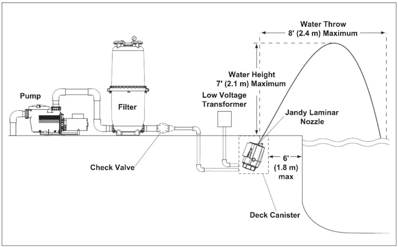
Each laminar jet requires a 1½ to 2 in (38 - 50 mm) PVC main feed line with 1 in (25 mm) PVC entering the deck canister. A check valve is also required and should be placed as far from the deck canister as possible to minimize water turbulence.
2.4 LED Light Module
The 12V LED light module offers vibrant lighting in nine (9) brilliant colors and five (5) festive color shows that can be controlled manually, by the AquaLink® RS Control System (Rev O or newer) or by the Jandy PDA Control System (Rev 4.0 or newer). The light module can be synchronized with Jandy's Pool and Spa LED lights and operates on less than 25 watts of power.
2.5 Conduit/Fiber Optics Module
If installing fiber optics, each laminar jet will require 100 to 150 strand fiber optic cable. One hundred-fifty strand cable is recommended due to the enhanced lighting effects.
2.6 Critical Placement Dimensions
The laminar jet can project a maximum of 7 feet (2.1 m) up and 8 feet (2.4 m) out into the water. Therefore, ensure the installation is no more than 6 feet (1.8 m) from the inside edge of the pool.
NOTE: To avoid water spray on the deck in high wind areas, place the laminar jet closer to the edge of the pool.
NOTE: The deck canister lid can only rotate approximately 90 degrees to the left or the right. Therefore, make sure that the deck canister is positioned towards the desired target location (see Installing the Deck Canister) prior to completing the installation.
text_image
Pump Filter Check Valve Low Voltage Transformer Water Height 7' (2.1 m) Maximum Water Throw 8' (2.4 m) Maximum Jandy Laminar Nozzle 6' (1.8 m) max Deck CanisterFigure 1. Basic Plumbing Diagram for Laminar Jet with Deck Canister
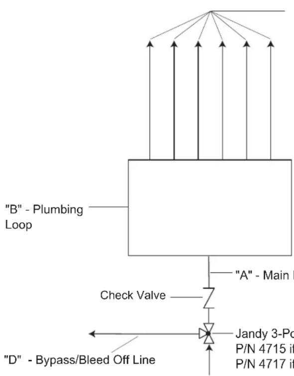
flowchart
graph TD
    A[""B" - Plumbing Loop"] --> B["Check Valve"]
    B --> C["Jandy 3-Po\nP/N 4715 if\nP/N 4717 if"]
    D[""D" - Bypass/Bleed Off Line"] --> E["Check Valve"]
    E --> F["A" - Main I"]
    style A fill:#f9f,stroke:#333
    style D fill:#f9f,stroke:#333
    style B fill:#ccf,stroke:#333
    style C fill:#cfc,stroke:#333
    style E fill:#fcc,stroke:#333
    style F fill:#cff,stroke:#333
"C" - Inlet Lines to
Laminar Jet Deck Canister
(Maximum 6 Lines per
Plumbing Loop)
Table 1. Multiple Jet Setup
| Number of Laminar Jets at rate of 10 gallons per min (38 lpm) | Recommended Pipe Size within 25' (7.6 m) of equipment (in/mm) | |||
| A B C D | ||||
| 2 | 112 / 38 | / 25.4 1 / | 25.4 112 / 3 | 3 |
| 3 | 112 / 38 | 112 / 38 1 / | 25.4 112 / 3 | 3 |
| 4 | 2 / 50.8 | 112 / 38 1 / | 25.4 2 / 50. | 3 |
| 5 | 2 / 50.8 | 112 / 38 1 / | 25.4 2 / 50. | 3 |
| 6 | 2 / 50.8 | 112 / 38 1 / | 25.4 2 / 50. | 3 |
"A" - Main Feed Line
Jandy 3-Port Valve
P/N 4715 if "A" is 1 12 " (38 mm) or
P/N 4717 if "A" is 2" (50.8 mm)
Note: If using a high head pump,
plumb a cartridge filter inline.
Figure 2. Plan View of Plumbing Loop for Multiple Laminar Jets
Section 3. Installing the Deck Canister
NOTE: Prior to installing the Jandy Laminar Jet deck canister, locate the jet opening (slot) in the deck canister cover. Make sure that this opening is pointing towards the desired target location in the pool. Use the water stand pipe as a reference. Determining the orientation of the deck canister will also establish where to place the plumbing and fiber optic conduit.
NOTE: The deck canister lid can only rotate approximately 90 degrees to the left or the right. Therefore, make sure that the deck canister is positioned towards the desired target location prior to completing the installation.
3.1 In-Deck Installation
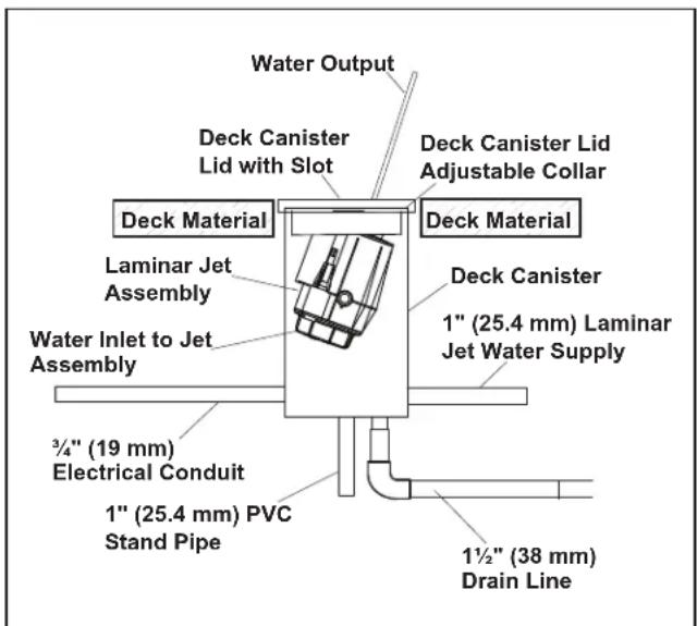
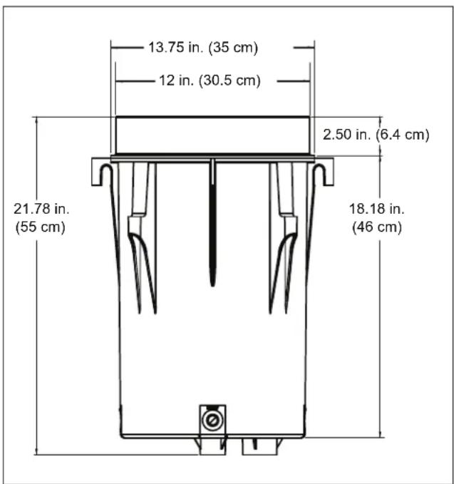
- Dig the hole for the deck canister approximately 24 inches deep and 18 inches in diameter. This will ensure enough room for positioning the canister and laying out the plumbing. This depth also allows for the addition of a layer of pea gravel, about 1/8 to 1/4" size (3-6 mm), for stability and additional drainage. Refer to deck canister dimensions.
text_image
Water Output Deck Canister Lid with Slot Deck Material Deck Canister Lid Adjustable Collar Laminar Jet Assembly Deck Material Deck Canister 1" (25.4 mm) Laminar Jet Water Supply Water Inlet to Jet Assembly 3/4" (19 mm) Electrical Conduit 1" (25.4 mm) PVC Stand Pipe 1½" (38 mm) Drain LineFigure 3. Laminar Jet Deck Canister Schematic
text_image
13.75 in. (35 cm) 12 in. (30.5 cm) 2.50 in. (6.4 cm) 21.78 in. (55 cm) 18.18 in. (46 cm)Figure 4. Deck Canister Dimensions
text_image
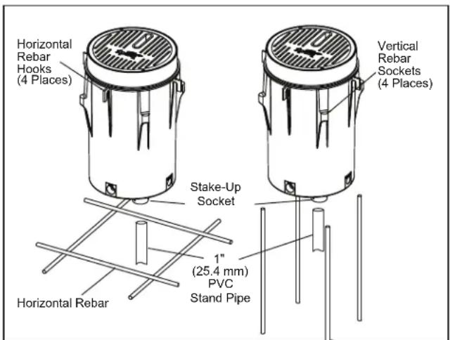
Horizontal Rebar Hooks (4 Places) Vertical Rebar Sockets (4 Places) Stake-Up Socket Horizontal Rebar 1" (25.4 mm) PVC Stand PipeFigure 5. Deck Canister Rebar Hooks and Sockets
- Set the deck canister in the hole. The top edge of the lid/collar should be flush with the finished deck, after the deck material is poured.
NOTE: To ensure that the canister stays upright while installing and leveling the unit, place a 6 inch (15 cm) piece of 1 inch (25.4 mm) PVC pipe in the construction support stake-up socket located on the bottom of the canister.
-
Level the deck canister. To hold the canister in place while the deck is poured, secure the canister by tying it with tie wire to the steel framework of the deck. To mount level, horizontal rebar hooks and vertical rebar sockets are provided around the outside of the canister.
-
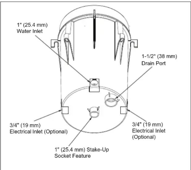
Plumb the incoming filtered water supply to the 1 inch (25.4 mm) hub located on the side of the deck canister marked "Inlet". The filtered water supply must include a check valve.
- Plumb the conduit for the fiber LED cable to the 3/4 inch (19 mm) socket located either side of the deck canister marked "Electrical". Refer to fiber optic installation instructions.
text_image
1" (25.4 mm) Water Inlet 1-1/2" (38 mm) Drain Port 3/4" (19 mm) Electrical Inlet (Optional) 3/4" (19 mm) Electrical Inlet (Optional) 1" (25.4 mm) Stake-Up Socket FeatureFigure 6. Deck Canister - Bottom View
NOTE: Use one (1) of the two (2) electrical inlets, located on either side of the deck canister, which are provided for installation ease.
- Plumb in the 112 inch (38 mm) drain line. Adequate drainage must be provided for the deck canister.
NOTE: Proper drainage for the deck canister is critical to avoid damage to the laminar jet assembly.
-
Verify the deck canister is level.
-
Place the adjustable deck lid collar back on the canister. This collar allows the installer to make fine adjustments when leveling the canister to be flush with the deck's finished surface. Set the collar at the finished deck level and pour the deck.
3.2 Out-of-Deck/Planter Box Installation

CAUTION
Do not install the Jandy Laminar Jet deck canister in an area prone to run-off or flooding or on a flammable surface.
NOTE: The deck canister lid can only rotate approximately 90 degrees to the left or the right. Therefore, make sure that the deck canister is positioned towards the desired target location prior to completing the installation.
- Dig the hole for the deck canister approximately 24 inches deep and 18 inches in diameter (60 cm deep, 45 cm diameter). This will ensure enough room for positioning the canister and laying out the plumbing. The dimensions allow for the addition of a layer of pea gravel, about 1/8 to 1/4" size (3-6 mm), for drainage, as well as room to pour concrete around the outside of the canister for stability.
NOTE: Proper drainage for the deck canister is critical to avoid damage to the laminar jet assembly. - Lift up the lid and jet assembly and adjustable deck lid collar from the deck canister.
NOTE: To ensure that the canister stays upright while installing and leveling the unit, place a 6 inch (15 cm) length of 1 inch (25.4 mm) PVC pipe in the stake-up socket feature located on the bottom of the canister. - Set the deck canister in the hole. The canister should be approximately 112 -2 inches (38-50 mm) above the finished grade in the planter.
NOTE: Unlike the in-deck installation, the deck canister cover cannot be flush with the finished grade. It must sit slightly above the surface to prevent water and debris from seeping into the canister. - Level the deck canister. To hold the canister in place, position a 6 inch piece (15 cm) of 1 inch (25.4 mm) PVC pipe in the construction support socket located on the bottom of the canister.
- Plumb the incoming, filtered water supply to the 1 inch (25.4 mm) hub located on the bottom of the deck canister marked "Inlet". The filtered water supply must include a check valve.
- Plumb the conduit for the fiber/LED cable to the 1 inch (25.4 mm) hub located on the bottom of the deck canister marked "Electrical". Refer to fiber optic installation instructions.
- Plumb in the 1½ inch (38 mm) drain line located on the bottom of the deck canister. Adequate drainage must be provided for the canister.
- Fill in the hole surrounding the deck canister with concrete or suitable backfill material for stability in the ground.
- Place the adjustable deck lid collar back on the canister.
3.3 Pressure Test Water Lines
WARNING
The maximum operating pressures for pumps, filters, and other equipment are specified in their individual installation/operating instructions. Never subject the system to test or operating pressures exceeding these specifications. Pressures above maximum component operating ratings can cause product failure, or also cause the filter lid to be blown off, or other equipment failure which can result in death, serious personal injury, or property damage.
The unit is shipped ready for the pressure test with a cap on the flexible hose that is attached to the canister.
NOTE: This cap can be used to winterize the system or service the unit, if needed.
When performing hydrostatic pressure tests or when testing for external leaks of the completed filtration and plumbing system, ensure that the maximum pressure the filtration system is subjected to does not exceed the maximum working pressure of any of the components within the system.
3.4 Flush Water Lines
It is important that prior to reinstalling the laminar jet and deck canister lid, the installer must turn on the water source and flush the lines of any debris.
NOTE: The finger screen is installed in the fitting under the cap. Remove the finger screen when flushing the line and reinstall the screen when reinstalling the cap or the jet assembly.
Section 4. Laminar Jet with LED Light Installation (Use with JLLLED4C Series)
WARNING
Risk of Electrical Shock or Electrocution which may result in serious injury or death. The Jandy Laminar Jet are only available for 12-volt AC power. For supply connection, use only an isolating low voltage power supply with ungrounded output, listed by an NRTL for swimming pool use. A Ground Fault Circuit Interrupter (GFCI) for 120 Volt transformers should be used if required by the transformer manufacturer or if required by the local applicable code and/or Authority Having Jurisdiction (AHJ). When a GFCI is used, the conductors on the load side of the GFCI circuit shall not occupy conduit, boxes, or enclosures containing other conductors unless the additional conductors are also protected by a GFCI. Refer to local codes for complete details. This laminar jet with LED light must be installed by a licensed or certified electrician or a qualified pool serviceman in accordance with the National Electrical Code® and all applicable local codes and ordinances. Improper installation will create an electrical hazard, which could result in death or serious injury to pool or spa users, installers or others due to electrical shock, and may also cause damage to property.
WARNING
Always disconnect the power to the laminar jet with LED light at the circuit breaker before installing or servicing the light. Failure to do so could result in death or serious injury to serviceman, pool or spa users or others due to electrical shock.
4.1 Preparing the Laminar Jet with LED Light for Installation
NOTE: The electrician must complete preparatory steps before the laminar jet with LED light is installed.
Ensure that the pool meets the requirements of the current National Electrical Code and all local codes and ordinances. A licensed or certified electrician must install the electrical system to meet or exceed those requirements before the laminar jet with LED light is installed. Some of the requirements of the National Electrical Code, which the pool electrical systems must meet, are as follows:
-
The low voltage transformer must be located at least 8 inches (20 cm) above water level, at least 4 inches (10 cm) above ground level, and at least 4 feet (1.2 m) from the edge of the pool.
-
All metal items within 5 feet (1.5 m) of the pool must be properly electrically bonded to a reliable point of grounding.
4.2 Installing the Laminar Jet with LED Light
NOTE: Perform these steps only after the electrical system requirements are met.
-
Feed cord through conduit to low voltage transformer, leaving at least 4 feet of cord at the light fixture to coil into the deck canister. The 4 feet (1.2 m) of cord allows the light to be easily serviced.
-
Cut the cord at the low voltage transformer, leaving at least 6 inches (15 cm) of cord to make connections.
-
Strip 6 inches (15 cm) of the outer cord jacket to expose the three (3) insulated wires. Be careful not to damage the insulation on the three (3) inner wires.
-
Install strain relief over cord jacket and connect all three (3) wires to the corresponding circuit wires in the low voltage transformer. Install the low voltage transformer cover.
-
Turn on main switch or circuit breaker, and the switch, which operates the laminar jet with LED light, to check for proper operation. Refer to operating instructions.
flowchart
graph TD
    A["120 VAC Power Supply"] --> B["Line 1"]
    A --> C["Line 2"]
    A --> D["Line 3"]
    A --> E["Aux 3 Relay"]
    A --> F["Filter Pump Relay"]
    A --> G["Alternative Control Panel"]
    A --> H["Alternative Control Panel"]
    A --> I["Laminar Jet with LED Light"]
    A --> J["Neutral Ground"]
    A --> K["Ground"]
    A --> L["Black White Green"]
    A --> M["120V/12V Transformer"]
    M --> N["Black White Green"]
    M --> O["JUNCTION BOX"]
    O --> P["Black White Green"]
    style A fill:#f9f,stroke:#333
    style M fill:#ccf,stroke:#333
    style O fill:#ccf,stroke:#333
    style P fill:#ccf,stroke:#333
    note right of M: *Transformer must be supplied by a GFCI if required by the transformer manufacturer's instructions, or by local code and AHJ requirements
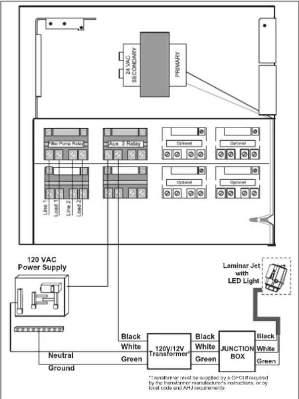
Figure 7. 12-Volt Laminar Jet with LED Light Wiring Diagram
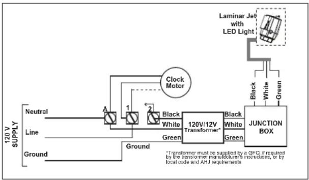
flowchart
graph LR
    A["Neutral"] --> B["Line"]
    B --> C["Ground"]
    D["Clock Motor"] --> E["120V/12V Transformer*"]
    E --> F["JUNCTION BOX"]
    G["Laminar Jet with LED Light"] --> H["Black White Green"]
    I["Black White"] --> E
    J["Green"] --> E
    K["*Transformer must be supplied by a GFCI if required by the transformer manufacturer's instructions, or by local code and AHJ requirements"]
Figure 8. Wiring the Laminar Jet with LED Light to a Time Clock
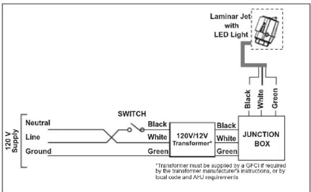
flowchart
graph LR
    A["120 V Supply"] --> B["Neutral"]
    A --> C["Line"]
    A --> D["Ground"]
    B --> E["Switch"]
    C --> E
    D --> E
    E --> F["120V/12V Transformer*"]
    F --> G["JUNCTION BOX"]
    G --> H["Laminar Jet with LED Light"]
    H --> I["Black White Green"]
    G --> J["Black White Green"]
    style A fill:#f9f,stroke:#333
    style G fill:#ccf,stroke:#333
Figure 9. Wiring the Laminar Jet with LED Light to a Switch
4.3 Wiring Options for Controlling Laminar Jet with LED Lights
NOTE: The laminar jet with LED lights will not operate properly with light dimmers. Do not wire the laminar jet with LED lights to any dimming circuitry.
To the extent allowed by code and capacity of the electrical equipment, multiple laminar jets with LED lights may be controlled with a single switch so their colors will always be synchronized.
Separate switches may be used to control the on/off and color functions of each laminar jet with LED light. It is recommended that these switches be located next to each other to facilitate simple color synchronization when desired. All switches must be operated at the same time to assure color synchronization. Otherwise, the lights will work independently of each other.
4.3.1 Wiring to an AquaLink® RS Control System
The laminar jet with LED light can be wired into the Jandy AquaLink RS control system to provide simplified operation of the lights, as well as a means to synchronize the color change function. Connect the laminar jet with LED lights to one of the auxiliary relays in the Power Center.
NOTE: It is recommended to connect one (1) laminar jet with LED light per relay so each light can be controlled separately. However, up to four (4) laminar jets with LED lights can be connected on a single relay. If there are more than four (4) lights installed on one (1) AquaLink RS system, ensure there is more than one (1) auxiliary relay available in the Power Center.
Connect the laminar jet with LED lights to the power center.
NOTE: The laminar jet with LED light operates only on 12 volts AC. A suitable 120-volt/12-volt stepdown AC transformer MUST be used. Read further for more important details.
4.3.2 Wiring to a Time Clock
The laminar jet with LED lights can be wired into a basic time clock to automatically turn on the laminar jet with LED lights at a predesignated time. Connect the laminar jet with LED lights into the time clock.
4.3.3 Wiring to a Switch
The laminar jet with LED lights can be wired into a switch to manually turn on/off the lights. Connect the laminar jet with LED lights into the switch.
4.4 Twelve (12) Volt Transformer Installation
The laminar jet with LED lights requires the use of a 120/12VAC-100 watt low voltage lighting transformer.
NOTE: For optimum performance Zodiac Pool Systems, Inc. recommends using one transformer per 12-volt laminar jet. However, it is possible to power up to 4 laminar jets with one 200 watt transformer.
To ensure maximum safety, the transformer used to power the laminar jet with LED lights must be one that is listed by a Nationally Recognized Testing Laboratory (NRTL) for the application.
NOTE: If the pool already has a low voltage transformer powering the pool and/or spa lights, do not use the same transformer to power the laminar jet with LED lights. This is to ensure that the laminar jet's LED lights are only turned on when the laminar jet pump is running.
Section 5. Laminar Jet with Fiber Optic Module Installation (Use with JLFBR Series)
5.1 Items Required
The tools and supplies necessary for installation of the fiber optic module:
| Tools | Utility knife or hot knife; Heat gun or propane torch. |
| Cable | Each jet requires 100 to 150 strands of fiber optic cable. Do not use more than 40 feet (12 m) of cable per nozzle as light output will be diminished. |
| Illuminator | Use illuminator with sufficient capacity of lighting effect intended. |
| Additional Materials | Electrical tape; Silicon (RTV) |
5.2 Installation
- Remove 6 inches (15 cm) of the cable jacket.
- Using black electrical tape, tightly tape over the exposed fiber leaving approximately 12 inch (13 mm) exposed fiber at the end of the cable. The tape prevents the individual fibers from separating.
- With a hot knife, cut the fiber optic cable so that the cable end is a flat surface. For best results, heat knife to cherry red.
NOTE: Do not cut the fiber ends too close to the taped edge. Leave a 14 inch (6 mm) distance between the cable end and the end of the taped edge. This will prevent adhesive on the tape from melting and getting on the ends of the fiber optic strands.
- Slide the completed fiber optic cable through the Heyco ^® * waterproof fitting and up the tube (located at the bottom of the jet) until the cable bottoms out on the lens inside unit. Secure the fiber by tightening the waterproof fitting.
*Heyco is a registered trademark of Heyco Products, Inc.
NOTE: Allow at least four (4) feet (1.2 m) of extra fiber optic cable in the deck canister to allow the laminar jet to be easily removed.
- Fill the electrical conduit between the opening and the fiber optic cable with RTV silicon to prevent water from entering the conduit. Let dry. The unit is now ready for operation.
- Install illuminator and attach fiber optic cable according to instructions supplied with the illuminator.
Section 6. Starting the System
6.1 Install Jet Assembly
- Disconnect the pressure cap that is installed on the flexible PVC hose.
NOTE: The system should be pressure tested before starting the system. - Flush water lines to clear debris. Lines must be clear of debris before attaching the laminar jet assembly.
NOTE: The finger screen is installed in the fitting under the cap. Remove the finger screen when flushing the line and reinstall the screen before installing the laminar jet assembly. - Connect the nut on the flexible hose of the laminar jet assembly and the threaded union of the flexible hose attached to the deck jet canister.
6.2 Set up Jet
- Place the jet assembly into the canister and align the mounting brackets to the collar.
- Ensure the flow adjustment valve is open by turning it counter-clockwise until it stops with a screw driver or a 1/2" (12.7 mm) socket wrench.
- Turn on the water at a reduced rate and slowly fill the unit. When the unit is filled, increase the water supply until the jet stream reaches its intended target.
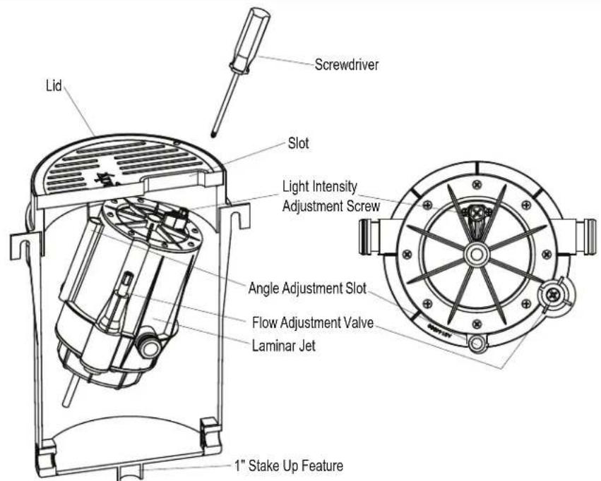
text_image
Screwdriver Lid Slot Light Intensity Adjustment Screw Angle Adjustment Slot Flow Adjustment Valve Laminar Jet 1" Stake Up FeatureFigure 10. Laminar Jet Light and Flow Adjustment
- Use the flow adjustment valve to make final adjustments to the overall water height of the jets.
NOTE: Laminar jets are sensitive to wind, earth movement and equipment vibration. Secure the laminar jet and deck canister to minimize vibration. Periodic stream distortion caused by pump vibrations and motor electrical fluctuations is normal and not indicative of a nozzle defect. Also, occasionally a nozzle will "burp" due to pumped air collecting in the nozzle body. This is normal and will occur until all air is purged from the piping system. Trapped air can also cause slight distortion in water action. It is imperative that all air is removed to ensure proper water feature operation.
- To adjust the angle of the jet move the laminar jet up or down to increase or decrease the angle by hand or using a screwdriver in the angle adjustment slot.
NOTE: The angle can be adjusted approximately 10^ .
-
The laminar jet is installed on two (2) pivots. Loosen the locking screws to adjust the jet angle. Once you are satisfied with the angle and location of the jet, tighten the locking screws.
-
Secure the deck canister lid to the deck canister collar, using two (2) #10 by 1½ inch (38 mm), Phillips flat head stainless steel screws.
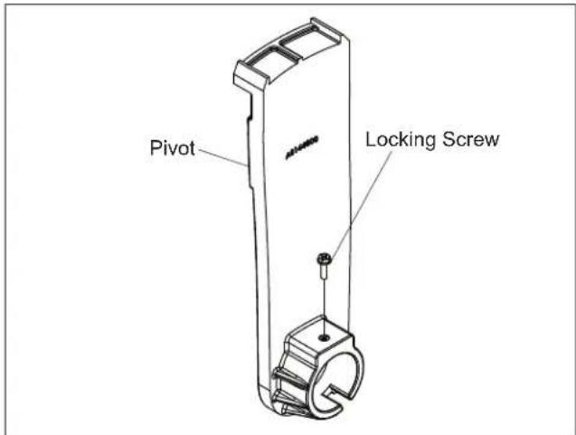
text_image
Pivot Locking ScrewFigure 11. Locking Screw Location
NOTE: It is recommended to drill 1/8" (3 mm) pilot holes in the lid. Then the screws can be threaded into the holes. This will complete the installation and secure the jet from movement.
Section 7. Operating the Laminar Jet with LED Light
7.1 To Operate the Light and Change Colors
Turn the light ON. The first time the light is turned on, the color sequence begins with the Alpine White. To change the color, turn the light OFF and then ON within three (3) seconds. Continue turning OFF and ON until the desired light color mode is reached.
Table 2. Jandy Laminar Jet with LED Lights Sequence
Sequence Order Color Modes
| 1 Alpine White |
| 2 Sky Blue |
| 3 Cobalt Blue |
| 4 Caribbean Blue |
| 5 Spring Green |
| 6 Emerald Green |
| 7 Emerald Rose |
| 8 Magenta |
| 9 Violet |
| 10 Slow Color Splash |
| 11 Fast Color Splash |
| 12 America the Beautiful |
| 13 Fat Tuesday |
| 14 Disco Tech |
NOTE: When the light is turned OFF for more than seven (7) seconds, it will remain in the color set that is currently active. When the light is turned back ON, the light will be on the same color set.
7.2 To Reset to the Beginning of the Color Sequence
Turn the light OFF, wait four (4) to six (6) seconds, then turn ON, the light will return to the beginning of the color cycle (Alpine White).
NOTE: If an AquaLink® RS control system is being used the color set can be selected using the controller.
NOTE: To synchronize colors on multiple Jandy WaterColors light systems and Jandy Laminar Jets with LED Lights wired to separate switches, preform the above actions on all of the switches simultaneously. All Jandy WaterColors lights and Jandy Laminar Jet with LED lights will synchronize automatically if activated by the same switch. No other accessories are required.
Section 8. Light Intensity Set Up
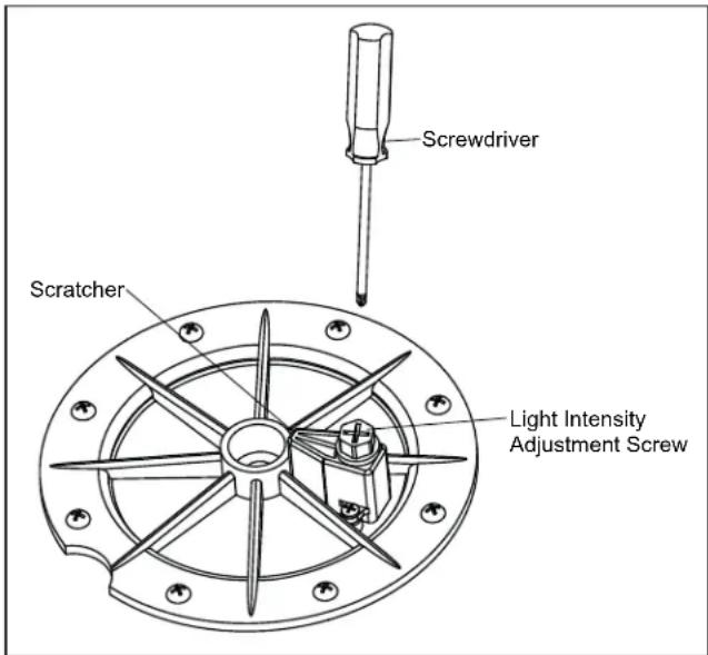
8.1 Light Intensity Adjustment Set
NOTE: The LED light intensity can be adjusted to your preference. Increased water stream flow will cause a greater disturbance of the laminar jet stream and create a more intense light.
-
Use the light intensity adjustment screw attached to the scratcher to adjust the light intensity.
-
To increase the light intensity, turn the screw counter-clockwise to increase the water stream coming out of the scratcher. This water stream disturbs the surface of the laminar jet flow causing an increase in the light intensity.
text_image
Screwdriver Scratcher Light Intensity Adjustment ScrewFigure 12. Scratcher Assembly and Light Intensity Adjustment Screw
NOTE: Laminar jets are sensitive to wind, earth movement and equipment vibration. Secure the laminar jet and deck canister to minimize vibration. Periodic stream distortion caused by pump vibrations and motor electrical fluctuations is normal and not indicative of a nozzle defect. Also, occasionally a nozzle will "burp" due to pumped air collecting in the nozzle body. This is normal and will occur until all air is purged from the piping system. Trapped air can also cause slight distortion in water action. It is imperative that all air is removed to ensure proper water feature operation.
Section 9. General Maintenance and Troubleshooting
CAUTION
The light engine assembly in the Jandy Laminar jet is sealed and therefore contains no serviceable parts. In order to prevent risk of property damage and/or injury, no service should be attempted to the light engine assembly in the event of a malfunction. The complete light engine assembly must be replaced.
Perform routine maintenance on the filter to ensure trouble-free nozzle operation. Be careful not to allow debris to enter the inlet plumbing when cleaning filters.
NOTE: Always flush lines after cleaning and backwash of filters.
9.1 Clogged Finger Screen
- If the finger screen becomes clogged with debris causing the stream to be distorted, remove the laminar jet assembly by unscrewing the two (2) deck canister lid retaining screws.
- Remove the deck canister lid and the jet assembly and place on the deck. Disconnect the union located on the flexible hose attached to the bottom of the jet assembly.
- Remove the finger screen from the union and clean with a garden hose.
NOTE: Avoid damage to the nozzle opening. After clean up, reinstall the unions.
9.2 Winterization
The laminar jet can be winterized in regions that require winterization.
- Remove the deck canister lid assembly and unscrew the 12 inch (13 mm) union.
- Thread the cap on the flexible hose attached to the deck canister. The laminar jet can then be replaced in the deck canister or may be removed to a storage location. If left in the deck canister, tape over the slot opening to ensure no water will enter the system. If fiber optic cable is used, be sure to remove the retaining nut on the waterproof fitting on the bottom of the jet assembly.
Section 10. Parts List and Exploded View
10.1 Parts List
| Key No. | Description Model | Order Part No. |
| 1 RGBW LED Light Engine Assembly, Laminar Jet | All R0961200 | |
| 2 Fiber Optic Assembly, Laminar Jet | All R0488900 | |
| 3 Deck Canister, Laminar Jet All R0489100 | ||
| 4 Jet Assembly, Laminar Jet (No Light Module) | All R0489200 | |
| 5 Cover and Screens (5), Laminar Jet Assembly | All R0489300 | |
| 6 Mounting Brackets and Hardware, Laminar Jet | All R0489500 | |
| 7 Rebuild Kit, All Hardware, Scratcher, Finger Screen & Unions | All R0490000 | |
| 8 Lid and Collar, Pebble, Laminar Jet | All JLPBL | |
| Lid and Collar, Pewter, Laminar Jet | All JLPWTR | |
| 9 Laminar Jet with RGBW LED Light Replacement Kit | All R0960900 | |
| 10 Laminar Jet with Fiber Optic Retrofit Kit | All R0500300 | |
NOTE: If the electrical cord of the LED light assembly is damaged, the entire LED light engine assembly (R0960900) must be replaced.
10.2 Exploded View
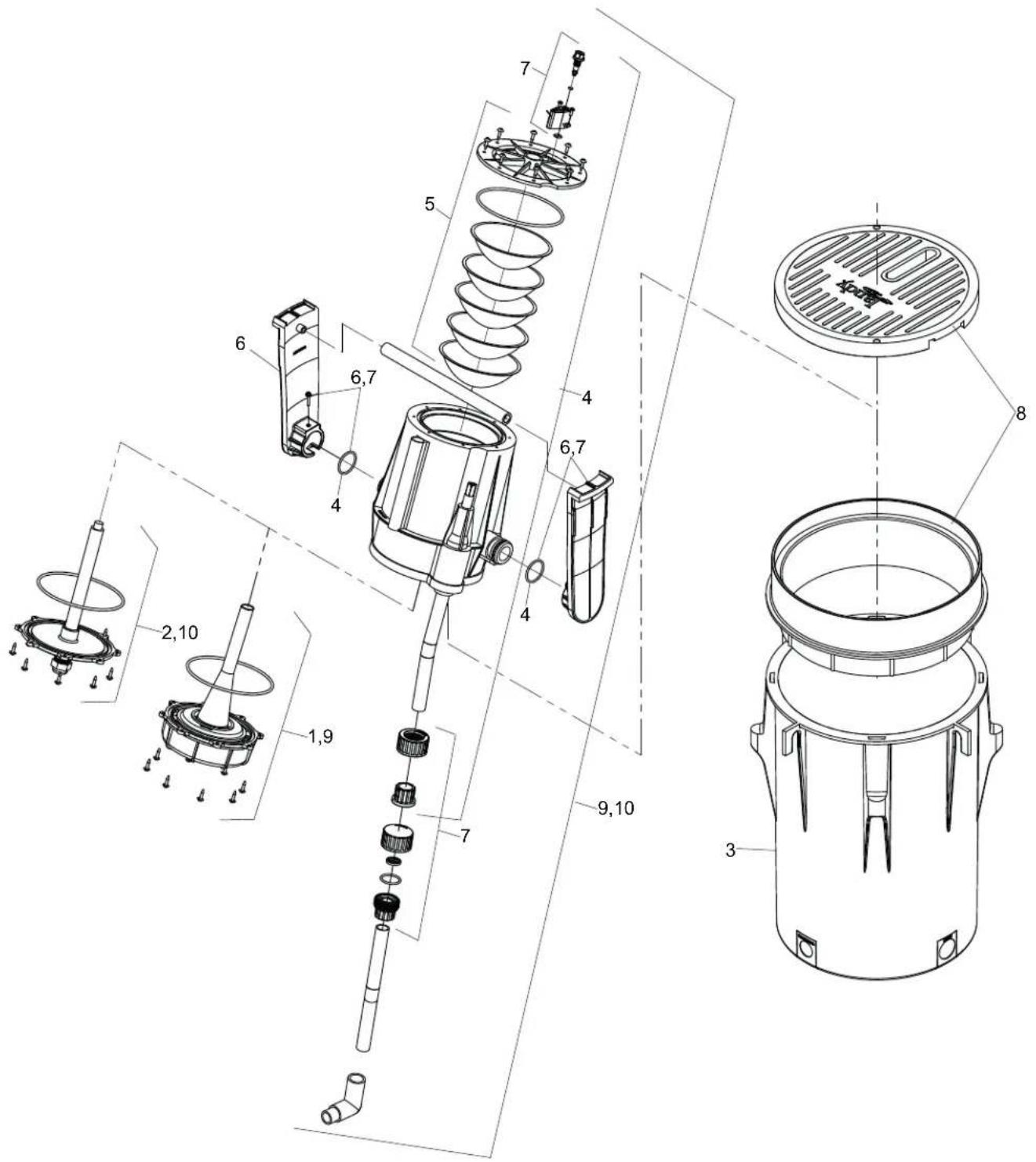
text_image
Technical diagram of a mechanical device with numbered components and exploded view, likely for assembly or maintenance purposes.Zodiac Pool Systems LLC
2882 Whiptail Loop # 100
Carlsbad, CA 92010
Fluidra Group Australia Pty Ltd
219 Woodpark Road
Smithfield, NSW AU 2164
USA | Jandy.com | 1.800.822.7933
AUS | Zodiac.com.au | 1.800.688.552
©2021 Zodiac Pool Systems LLC. All rights reserved. ZODIAC® is a registered trademark of Zodiac International, S.A.S.U., used under license. All other trademarks are the property of their respective owners.
H0771400_REVA
natural_image
Black-and-white photo of a fountain with water jets and decorative plants in the background (no visible text or symbols)Fontaine Laminar Jandy
Série JLLLED4C
Série JLFBR
AVERTISSEMENT
text_image
Technical diagram of a mechanical device with numbered components and exploded view, likely for assembly or maintenance purposes.Zodiac Pool Systems LLC
2882 Whiptail Loop # 100
Carlsbad, CA 92010
Fluidra Group Australia Pty Ltd
219 Woodpark Road
Smithfield, NSW AU 2164
AUS | Zodiac.com.au | 1.800.688.552
natural_image
Black-and-white photo of a fountain with water jets and decorative plants in the background (no visible text or symbols)Jet laminar Jandy
Serie JLLLED4C
Serie JLFBR
ADVERTENCIA
text_image
Technical diagram of a mechanical device with numbered components and exploded view, likely for assembly or manufacturing purposes.Zodiac Pool Systems LLC
2882 Whiptail Loop # 100
Carlsbad, CA 92010
Fluidra Group Australia Pty Ltd
219 Woodpark Road
Smithfield, NSW AU 2164
EE. UU. | Jandy.com | 1.800.822.7933
AUS | Zodiac.com.au | 1.800.688.552