
JCP073ATN - Pump Jandy - Free user manual and instructions
Find the device manual for free JCP073ATN Jandy in PDF.
| Product Type | Pool Pump |
| Brand | JANDY |
| Model | JCP073ATN |
| Motor Power | 7.5 HP (5.6 kW) |
| Supply Voltage | 208-230/460 V three-phase, 60 Hz |
| Rated Speed | 3450 RPM |
| Service Factor | 1.15 |
| Dimensions (L x W x H) | Approx. 106.7 cm x 86.4 cm x 34.3 cm |
| Shipping Weight | Approx. 89.4 kg |
| Suction Connection | 6-inch ANSI 150 Flange |
| Discharge Connection | 4-inch ANSI 150 Flange |
| Motor Type | NEMA JM, TEFC, Class H insulation |
| Mechanical Seal | 316 Stainless Steel / EPDM type 2100 |
| Maximum Working Pressure | 2.41 bar (35 PSI) |
| Maximum Water Temperature | 38 °C (100 °F) |
| Main Functions | Pool water filtration and circulation, priming, high-performance pumping |
| Maintenance and Cleaning | Daily cleaning of strainer basket, check O-rings, winter draining |
| Safety | Built-in thermal protection (single-phase), grounding, mandatory ground fault circuit breaker, entrapment prevention |
| Spare Parts Available | Full list in Section 8 of the manual: seals, basket, seal, impeller, etc. |
| Certifications | NSF/ANSI 50, UL 1081, CSA C22.2 No. 108 |
Frequently Asked Questions - JCP073ATN Jandy
User questions about JCP073ATN Jandy
0 question about this device. Answer the ones you know or ask your own.
Ask a new question about this device
Download the instructions for your Pump in PDF format for free! Find your manual JCP073ATN - Jandy and take your electronic device back in hand. On this page are published all the documents necessary for the use of your device. JCP073ATN by Jandy.
USER MANUAL JCP073ATN Jandy
natural_image
Technical line drawing of a mechanical pump or motor assembly (no text or symbols visible)JCP Series High Performance Commercial Pumps
JCP05-1CT-N JCP05-1CT-S
JCP07-1BD-N JCP07-1BD-S
JCP05-3AT-N JCP05-3AT-S
JCP07-3AT-N JCP07-3AT-S
JCP10-3AT-N JCP10-3AT-S
JCP15-3AT-N JCP15-3AT-S
WARNING
FOR YOUR SAFETY - This product must be installed and serviced by a contractor who is licensed and qualified in pool equipment by the jurisdiction in which the product will be installed where such state or local requirements exist. The maintainer must be a professional with sufficient experience in pool equipment installation and maintenance so that all of the instructions in this manual can be followed exactly. Before installing this product, read and follow all warning notices and instructions that accompany this product. Failure to follow warning notices and instructions may result in property damage, personal injury, or death. Improper installation and/or operation may void the warranty.

Improper installation and/or operation can create unwanted electrical hazard which can cause serious injury, property damage, or death.
ATTENTION INSTALLER - This manual contains important information about the installation, operation and safe use of this product. This information should be given to the owner/operator of this equipment.
Table of Contents
Section 1. Important Safety Instructions .....3
1.1 Safety Instructions....3
1.2 Pool Pump Suction Entrapment Prevention Guidelines 5
Section 2. General Description ...... 6
2.1 JCP Series Pump Operations.... 6
Section 3. Mechanical and Electrical Installation and Pressure Testing....7
3.1 Pump Handling....7
3.2 Pump Location 7
3.3 Mechanical Installation 8
3.4 Electrical Installation....8
3.5 Strainer Pot Service 10
3.6 Pressure Testing, Strainer Pot....11
Section 4. Jandy JCP Pump Operation ..... 13
4.1 Priming 13
Section 5. Maintenance and Storage......14
5.1 Maintenance.... 14
5.2 Storage....14
Section 6. Servicing .... 15
6.1 Required Tools.... 15
6.2 Replacement Parts....15
6.3 Alternate Parts....15
6.4 Pump Disassembly....15
6.5 Pump Assembly.... 17
Section 7. Troubleshooting and Repair.....18
Section 8. Replacement Parts List......21
8.1 JCP R-Kit List 24
Section 9. Product Dimensions....28
Section 10. Product Specifications....30
10.1 Specifications 30
Section 11. Technical Data ...... 31
EQUIPMENT INFORMATION RECORD
DATE OF INSTALLATION
INSTALLER INFORMATION
INITIAL PRESSURE GAUGE READING (WITH CLEAR FILTER)
PUMP MODEL
HORSEPOWER
NOTES:
Section 1. Important Safety Instructions
READ AND FOLLOW ALL INSTRUCTIONS
1.1 Safety Instructions
All electrical work must be performed by a licensed electrician and conform to all national, state, and local codes. When installing and using this electrical equipment, basic safety precautions should always be followed, including the following:
| ⚠ WARNINGRISK OF SUCTION ENTRAPMENT HAZARD, WHICH, IF NOT AVOIDED, CAN RESULT IN SERIOUS INJURY OR DEATH. Do not block pump suction, as this can cause severe injury or death. Do not use this pump for wading pools, shallow pools, or spas containing bottom drains, unless the pump is connected to at least two (2) functioning suction outlets. Suction outlet (drain) assemblies and their covers must be certified to the latest published edition of ANSI®/ASME® A112.19.8, or its successor standard, ANSI/APSP-16. |
| ⚠ WARNINGTo reduce the risk of injury, do not permit children and/or people with reduced physical, sensory or mental capabilities or lack of experience to use this product. |
| ⚠ WARNINGTo reduce the risk of property damage or injury, do not attempt to change the valve position with the pump running. |
| ⚠ WARNINGJandy pumps are powered by a high voltage electric motor and must be installed by a licensed or certified electrician or a qualified swimming pool service technician. |
| ⚠ WARNINGDue to the potential risk of fire, electric shock, or injuries to persons, Jandy pumps must be installed in accordance with the National Electrical Code® (NEC®), all local electrical and safety codes, and the Occupational Safety and Health Act (OSHA). Copies of the NEC may be ordered from the National Fire Protection Association, 1 Batterymarch Park, Quincy, MA 02169, or from your local government inspection agency. |
| ⚠ WARNINGRISK OF ELECTRIC SHOCK, FIRE, PERSONAL INJURY, OR DEATH. (For all permanently installed units intended for use on 15 or 20 ampere, 120 through 240 volt, single phase branch circuits). Connect only to a branch circuit that is protected by a ground-fault circuit-interrupter protection for personnel (GFCI). Contact a qualified electrician if you cannot verify that the circuit is protected by a GFCI. A GFCI should be provided by the installer and should be tested on a routine basis. To test the GFCI, push the test button. The GFCI should interrupt power. Push the reset button. Power should be restored. If the GFCI fails to operate in this manner, the GFCI is defective. If the GFCI interrupts power to the pump without the test button being pushed, a ground current is flowing, indicating the possibility of electrical shock. Do not use the device. Disconnect the device and have the problem corrected by a qualified service representative before using. |
| ⚠ WARNINGIncorrectly installed equipment may fail, causing severe injury, property damage or death. |
WARNING
- Do not connect the system to an unregulated city water system or other external source of pressurized water producing pressures greater than 35 PSI.
- Trapped air in system can cause the filter lid to be blown off, which can result in death, serious personal injury, or property damage. Be sure all air is out of the system before operating.
WARNING
Jandy ^® pool equipment is pressure tested at the factory. Local codes may require the pool piping system to be subjected to a pressure test. BE SURE TO COMPLY WITH THE FOLLOWING SAFETY INSTRUCTIONS:
- Check all clamps, bolts, lids, lock rings and system accessories to ensure they are properly installed and secured before testing.
- RELEASE ALL AIR in the system before testing.
• Water pressure for test must NOT EXCEED 35 PSI.
• Water temperature for test must NOT EXCEED 100°F (38°C). - Limit test to 24 hours. After test, visually check system to be sure it is ready for operation.
NOTICE: These parameters apply to Jandy equipment only. For non-Jandy equipment, consult equipment manufacturer.
WARNING
Chemical spills and fumes can weaken pool/spa equipment. Corrosion can cause filters and other equipment to fail, resulting in severe injury or property damage. Do not store pool chemicals near your equipment.
CAUTION
Do not start pump dry! Running the pump dry for any length of time will cause severe damage and may void the warranty.
CAUTION
This pump is for use with permanently installed pools and may also be used with hot tubs and spas, if so marked. Do not use with storable pools. A permanently installed pool is constructed in or on the ground or in a building such that it cannot be readily disassembled for storage. A storable pool is constructed so that it may be readily disassembled for storage and reassembled to its original integrity.
CAUTION
Do not install within an outer enclosure. The pump requires adequate ventilation to maintain air temperature at less than the maximum ambient temperature rating listed on the motor rating plate.
CAUTION
In order to avoid premature failure or damage to the pump motor, protect the pump from direct water exposure from sprinklers, water runoff from rooftops and drainage, etc. Failure to comply may cause pump failure, and may also void warranty.

WARNING
SUCTION HAZARD. Can cause serious injury or death. Do not use this pump for wading pools, shallow pools or spas containing bottom drains, unless the pump is connected to at least two (2) functioning suction outlets.
1.2 Pool Pump Suction Entrapment Prevention Guidelines
CAUTION
The performance of Jandy pumps is based upon clear, cold, fresh water with suction conditions as shown on the performance curve. If used to pump other liquids, pump performance may differ from rated performance based on the different specific gravity, temperature, viscosity, etc. of the liquid being pumped. A standard pump may not be safe for pumping all types of liquids, such as toxic, volatile or chemical liquids, or liquids under extreme temperatures or pressures. Please consult Jandy catalogs as well as local codes and general references to determine the appropriate pumps for your particular application. Since it is impossible for us to anticipate every application of a Jandy pump, if you plan to use the pump for a non-water application, consult Jandy beforehand to determine whether such application may be proper or safe under the circumstances. Failure to do so could result in property damage or personal injury.
WARNING
Pump suction is hazardous and can trap and drown or disembowel bathers. Do not use or operate swimming pools, spas, or hot tubs if a suction outlet cover is missing, broken, or loose. The following guidelines provide information for pump installation that minimizes risk of injury to users of pools, spas, and hot tubs:
Entrapment Protection - The pump suction system must provide protection against the hazards of suction entrapment.
Suction Outlet Covers - All suction outlets must have correctly installed, screw-fastened covers in place. All suction outlet (drain) covers must be properly maintained. They must be replaced if cracked, broken, or missing. Drain covers must be listed/certified to the latest published edition of ANSI®/ASME® A112.19.8 or its successor standard, ANSI/APSP-16. The pool must be shut down and bathers must be restricted from entering the pool until any cracked, broken, or missing drain covers are replaced.
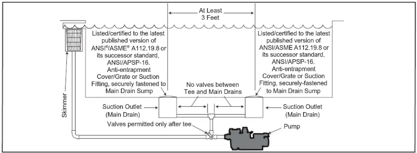
Number of Suction Outlets Per Pump - Provide at least two (2) hydraulically-balanced suction outlets, with covers, as suction outlets for each circulating pump suction line. The centers of the suction outlets (suction outlets) on any one (1) suction line must be at least three (3) feet apart, center to center. See Figure 1.
The system must be built to include at least two (2) suction outlets (drains) connected to the pump whenever the pump is running. However, if two (2) suction outlets run into a single suction line, the single suction line may be equipped with a valve that will shut off both suction outlets from the pump. The system shall be constructed such that it shall not allow for separate or independent shutoff or isolation of each drain. See Figure 1.
Additional pumps can be connected to a single suction line as long as the requirements above are met.
Water Velocity - The maximum water velocity through the suction outlet assembly and its cover for any suction outlet must not exceed the suction outlet assembly and its cover's maximum design flow rate. The suction outlet (drain) assembly and its cover must comply with the latest version of ANSI®/ASME® A112.19.8, the standard for Suction Fittings For Use in Swimming Pools, Wading Pools, Spas,and Hot Tubs, or its successor standard, ANSI/ASME APSP-16.
Testing and Certification - Suction outlet covers must have been tested by a nationally recognized testing laboratory and found to comply with the latest published edition of ANSI/ASME A112.19.8 or its successor standard, ANSI/APSP-16, the standard for Suction Fittings For Use in Swimming pools, Wading Pools, Spas, and Hot Tubs.
Fittings - Fittings restrict flow; for best efficiency use fewest possible fittings (but at least two (2) suction outlets).
Avoid fittings that could cause an air trap.
Pool cleaner suction fittings must conform to applicable International Association of Plumbing and Mechanical Officials (IAPMO) standards.
flowchart
graph TD
    A["Skimmer"] --> B["Listed/certified to the latest published version of ANSI®/ASME® A112.19.8 or its successor standard, ANSI/APSP-16. Anti-entrapment Cover/Grate or Suction Fitting, securely fastened to Main Drain Sump"]
    B --> C["Listed/certified to the latest published version of ANSI/ASME A112.19.8 or its successor standard, ANSI/APSP-16. Anti-entrapment Cover/Grate or Suction Fitting, securely fastened to Main Drain Sump"]
    C --> D["No valves between Tee and Main Drains"]
    D --> E["Suction Outlet (Main Drain)"]
    E --> F["Valves permitted only after tee"]
    F --> G["Pump"]
    G --> H["At Least 3 Feet"]
Figure 1. Proper Pump Suction Plumbing
Section 2. General Description
2.1 JCP Series Pump Operations
Jandy has created the new standard in commercial polymer pumps. The JCP series pump is engineered from the ground up to outperform the competition and provide years of quiet, efficient service. Our unique impeller and diffuser system delivers unparalleled priming performance while still achieving the hydraulic pump curves you demand. The JCP series also delivers several features which make it easy to use and service.
Competitive Features
- Drop-in replacement for C-series and EQ-series pumps.
- Easy-to-source motor replacements (standard JM-frame)
- Locking strainer lid with a robust, dependable radial seal o-ring.
- Unique strainer lid fitting to allow pressure or suction release.
- Standard, easily sourced Jandy drain-plugs.
- Spare parts kits to help service the pump faster.
Pump Technical Features
- Bolt-on optional strainer assembly
- 6" Suction and 4" Discharge ANSI flange connections
- NSF listed
• 316 SS/EPDM Type 2100 Mechanical Seal
• Type 21 Mechanical Seal Compatible
• Stainless Steel Hardware
Motor Technical Features
• Three Phase Motor Specs
- Class H Insulation
- AEGIS® Shaft Grounding Ring
- Stainless Steel Shaft Sleeve w/ Loctite® 648 Compound
- TEFC Motor Construction
° NEMA JM Frame
• NEMA Premium Efficiency
- Fluidra Patented Bonding Lug
• Inverter Ready: 20:1 VT & 4:1 CT
- F-1 Mounting
- Sealed Bearings
- Single Phase Motor Specs
- Class F Insulation
• TEFC Motor Construction (5HP) - ODP Motor Construction (7.5HP)
° NEMA JM Frame
• NEMA Standard Efficiency - Stainless Steel Shaft Sleeve w/ Loctite® 648 Compound
• Fluidra Patented Bonding Lug - F-1 Mounting
- Sealed Bearings
Section 3. Mechanical and Electrical Installation and Pressure Testing
3.1 Pump Handling
- Remove the corrugated box stapled to the crate and disassemble the crate using an electric drill with a philips head bit.
- Remove the 4 bolts holding the motor's base to the bottom of the crate.
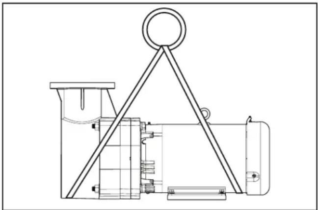
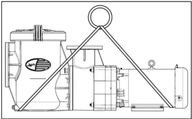
- See Figures 2-5 for hoist positions to lift the pump from the crate and into its final position. Some motors may have eye bolts located on the top of the motor. Do not use eye bolts solely to hoist the pump. Holes located on the inlet and outlet flanges must also be used as lifting locations. If the motor does not have an eye bolt, use straps to lift the pump.
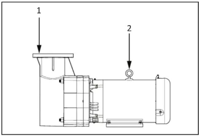
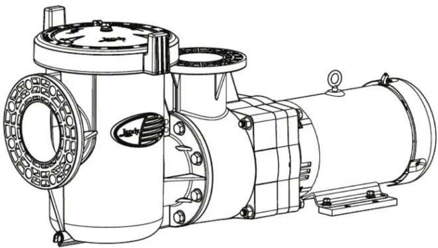
Figure 2. JCP - No Strainer Lift Points
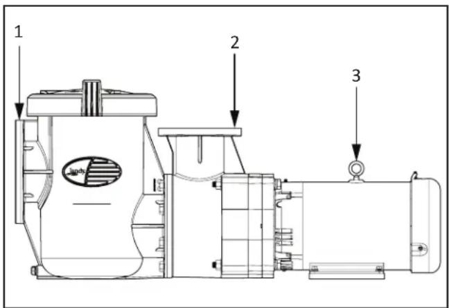
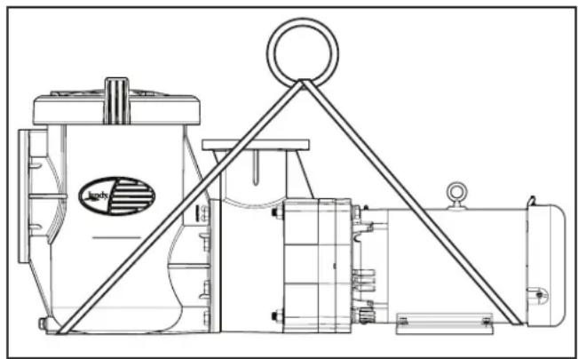
Figure 3. JCP With Strainer Lift Points
natural_image
Technical line drawing of a mechanical device with a triangular frame and mounting base (no text or symbols)Figure 4. JCP - No Strainer Strap Positions
natural_image
Technical line drawing of a mechanical device with no visible text or symbolsFigure 5. JCP With Strainer Strap Positions
3.2 Pump Location
- Locate the pump as close as possible to the pool (never more than 10 feet above pool water level).
- Install on a rigid foundation, preferably 2" or more above ground level. To further reduce the possibility of vibration noise, bolt the pump to the foundation.
- Provide the necessary space around the pump for future inspection and servicing of the unit. It is recommended that a louvered housing is used to protect exposed motors from the sun and rain. Allow for ventilation. Housing should clear the motors by a minimum of 10" at all points.

WARNING
To Reduce the Risk of Fire, install pool equipment in an area where leaves or other debris will not collect on or around the equipment. Keep surrounding area clear of all debris such as paper, leaves, pine-needles and other combustible materials.
CAUTION
In order to avoid premature failure or damage to the pump motor, protect the pump from direct water exposure from sprinklers, water runoff from rooftops and drainage, etc. Failure to comply may cause pump failure, and may also void warranty.
3.3 Mechanical Installation
- Carefully remove the pump assembly (or pump and strainer pot assembly) from its shipping packaging.
- Determine the installation location of the pump and strainer pot assembly. Ensure that adequate space and lighting is provided for routine maintenance.
- It is good practice to install a valve on the suction line before this unit and on the return line after the pump so that both items can be isolated for routine maintenance.
- Check that a section of straight pipe, with a length that is five times its diameter, is installed between the suction side of the pump and the first elbow. See Figure 8.
- Suction lines should be as large as the suction port of the pump. All piping must be air tight. Keep all suction lines below pool water level until just before the pump. Suction lines should slope toward the pump.
- Connect the pump to the suction pipe using a 6" ANSI-150 flange kit. Tighten the flange bolts to no more than 20-foot pounds. Excessive torque may damage the pump.
- Connect the pump to the discharge pipe using a 4" ANSI-150 flange kit. Tighten the flange bolts to no more than 20-foot pounds. Excessive torque may damage the pump.
- The weight of the piping should be supported independently and not carried by the pump.
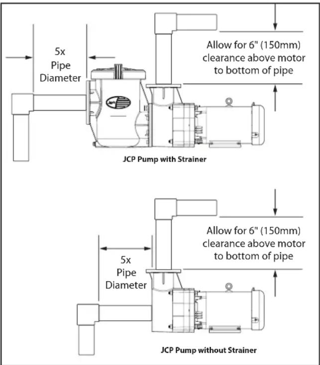
Figure 6. Jandy JCP Pipe Clearance
- Plan carefully the layout of adjacent plumbing including cutting pipe to the exact length and ensuring that the flange will be aligned and square with the strainer pot or pump assembly. Note that the strainer pot must be installed so that water flow travels into the upper flange and out the bottom flange.
NOTE: If the strainer pot assembly is installed as a stand alone unit, another straight piece of pipe at least 76 cm (30") long should be installed to connect the strainer assembly to the pump housing. Glue plumbing in place once you are certain that fit ups are correct.
CAUTION
Use large diameter flat washers (at least 1-5/16 in. outer diameter) between the hex nut and the strainer pot assembly flanges to properly distribute the clamping forces on the flanges. Tighten the flange bolts to 27.1 newton meter (20 ft-lb) unless otherwise specified by the flange manufacturer. If it is not possible to use a torque wrench then care should be taken not to over tighten the flange bolts. Failure to follow the above instructions can result in damaging the strainer pot flanges.
CAUTION
Suction and discharge piping must be supported by an appropriate system of supports or hangers. Inadequately supported pipe can cause excessive loads to be transmitted to the strainer pot assembly resulting in a structural failure that could result in flooding and property damage.
3.4 Electrical Installation
WARNING
Single phase pump models include built-in manual reset thermal overload protection to shut off the motor in the event the temperature becomes excessive (as a result of mechanical or electrical problems; such as low voltage, poor ventilation, overloaded lines, etc.). The motor thermal protection must be manually reset to commence operation after overload conditions have been corrected.
3-Phase pump motors are NOT thermally protected. Motor protection must be provided by the installer in accordance with local code.
3.4.1 Voltage Checks
Note: Do not try to connect three-phase motors to single phase power supply or single phase motors to three-phase power supply.
The correct voltage, as specified on the pump data plate, is necessary for proper performance and long motor life. Incorrect voltage will decrease the pump's ability to perform and could cause overheating, reduce the motor life, and result in higher electric bills.
It is the responsibility of the electrical installer to provide data plate operating voltage to the pump by ensuring proper circuit sizes and wire sizes for this specific application.
The National Electrical Code ^® (NEC ^® , NFPA-70 ^® ) requires all 120 through 240 volt single phase pool pump circuits be protected with a Ground Fault Interrupter (GFCI). Therefore, it is also the responsibility of the electrical installer to ensure that the pump circuit is in compliance with this and all other applicable requirements of the National Electrical Code (NEC) and any other applicable installation codes.

CAUTION
Failure to provide data plate voltage (+/- 10%) during operation will cause the motor to overheat and may void the warranty.
3.4.2 Bonding and Grounding

WARNING
ELECTRICAL SHOCK HAZARD
Turn off all switches and the main breaker in the pump electrical circuit before starting the procedure. Failure to comply may cause a shock hazard resulting in severe personal injury or death.
In addition to being properly grounded as described in the Electrical Wiring section, and in accordance with the requirements of the National Electrical Code (NEC), or in Canada the Canadian Electrical Code (CEC), the pump motor must be bonded to all metal parts of the swimming pool, spa or hot tub structure and to all electrical components and equipment associated with the pool/spa water circulation system. See Figure 7.
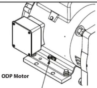
Bonding Lug
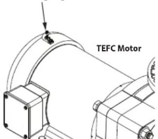
Figure 7. Bonding Lug Location
The bonding must be accomplished by using a solid copper conductor, No. 8 AWG or larger. In Canada No. 6 AWG or larger must be used. Bond the motor using the external bonding lug provided on the motor frame.
National Electrical Code® (NEC®) requires bonding of the Pool Water. Where none of the bonded pool equipment, structures, or parts are in direct connection with the pool water; the pool water shall be in direct contact with an approved corrosion-resistant conductive surface that exposes not less than 5800 mm² (9 in²) of the surface area to the pool water at all times. The conductive surface shall be located where it is not exposed to physical damage or dislodgement during usual pool activities, and it shall be bonded in accordance with the bonding requirements of NEC Article 680. Refer to locally enforced codes for any additional bonding requirements

WARNING
Always disconnect the power source before working on a motor or its connected load.
WARNING
Make sure that the control switch, time clock, or control system is installed in an accessible location, so that in the event of an equipment failure or a loose plumbing fitting, the equipment can be turned off. This location must not be in the same area as the pool pump, filter, and other equipment.
3.4.3 Electrical Wiring
- Secure the ground wire to the pump using the green screw provided. Ground before attempting to connect to an electrical power supply. Do not ground to a gas supply line.
- Wire size must be adequate to minimize voltage drop during the start-up and operation of the pump.
- Insulate all connections carefully to prevent grounding or short-circuits. Sharp edges on terminals require extra protection. For safety, and to prevent entry of contaminants, reinstall all conduit and terminal box covers. Do not force connections into the conduit box.
Wiring
Note: Due to wide variation in electrical equipment, power equipment, power supply, and installation requirements, this manual does not make specific recommendations concerning auxiliary equipment or fusing/wiring.
IMPORTANT NOTE: Confirm the direction of the pump motor rotation matches the directional arrow on the pump body. Failure to do so may cause pump failure, and may also void warranty. Check wiring diagram to determine if the motor can be field-wired to rotate in both directions.
Wire sizing, wire type, branch circuit fuse protection, motor starter, control equipment, and related items must meet National Electrical Code and local code requirements.
Motors are supplied by several manufacturers and nameplate data (service factor, maximum amperage, etc.) will vary. Consult control manufacturer and motor nameplate on your pump to correctly choose and size motor starter and control equipment for your particular installation. Specific electrical questions or problems should be addressed to the manufacturer of the electrical component in question.
Emergency Shutoff
Install an Emergency Shutoff Switch near pool. Clearly mark this switch and mount it in a location that is accessible to bathers or pool operating personnel (e.g. lifeguards). Make sure that all lifeguards and pool personnel understand the switch's use in case of emergency (entrapment, electrical malfunction, etc.).
3.5 Strainer Pot Service
- Make sure the pump is turned off if it is being controlled by a variable frequency drive.
- Make sure the circuit breaker that powers the pump motor is turned off.

CAUTION
The pump must be permanently connected to a dedicated electrical circuit. No other equipment, lights, appliances, or outlets may be connected to the pump circuit.

WARNING
ELECTRICAL SHOCK HAZARD
Turn off all switches and the main breaker in the pump electrical circuit before starting the procedure. Failure to comply may cause a shock hazard resulting in severe personal injury or death.

WARNING
ELECTRICAL SHOCK HAZARD
Due to the potential risk of fire, electric shock, or injuries to persons, Jandy® Pumps must be installed in accordance with the National Electrical Code® (NEC®), all local electrical and safety codes, and the Occupational Safety and Health Act (OSHA). Copies of the NEC may be ordered from the National Protection Association, 1 Batterymarch Park, Quincy, MA, 02169, or from your local government inspection agency.
In Canada, Jandy pumps must be installed in accordance with the Canadian Electrical Code (CEC).
- Make sure all necessary isolation valves are closed to prevent pool water from reaching the pump.
- Carefully remove the plug and O-ring seal located in the center of the lid. This will allow the pressure inside the pump to equalize with the pressure in the room.
IMPORTANT NOTE: Failure to remove the lid's center plug before service will significantly increase the difficulty of assembling or disassembling the lid and may cause the lid's lifting tabs to break.
- Follow the markings on the locking ring. Using both handles, slowly turn the locking ring counterclockwise until the lid and locking ring disengage from the pump housing. See Figure 8.
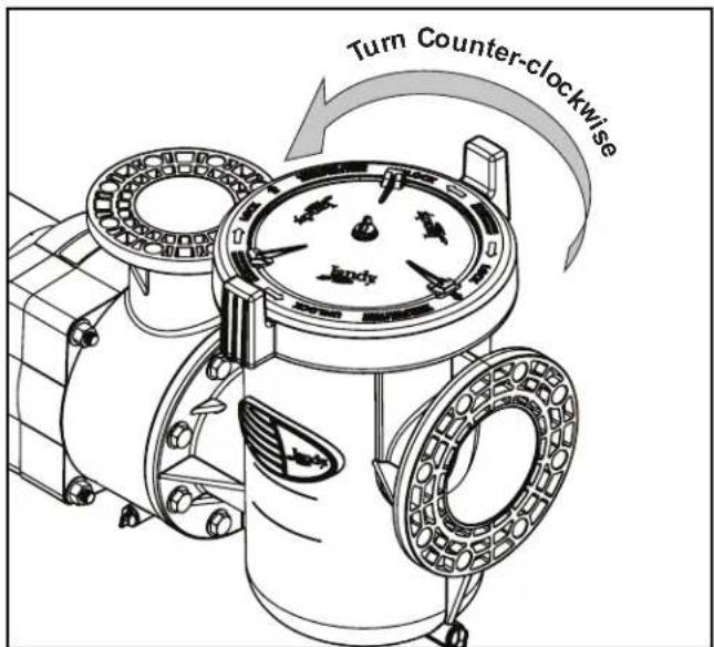
Figure 8. Disengage Lock Ring
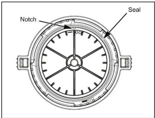
Figure 9. O-ring in Lid Assembly
- The lid assembly will disengage the pump body after approximately 45 degrees of rotation.
- Inspect the O-ring located in the lid for debris or damage. See Figure 9. If necessary, insert a flat head screw driver through the notch to assist in removing the O-ring. If there is any evidence of degradation, debris impregnation, or tearing of the O-ring, replace the seal immediately. Use only silicone based O-ring lubricants to assist in assembly.
- The strainer basket may be removed and emptied. Ensure the basket is lined up properly with the strainer's inlet port when placing the basket back into the strainer pot. See Figure 10.
- To reassemble the lid, align the arrows that indicate "Port" approximately 45 degrees counterclockwise from the inlet port. Turn the lid clockwise until the lid engages the pump body and the handles are perpendicular to the ports. The arrows will align with the ports. Install the lid's center plug and seal.
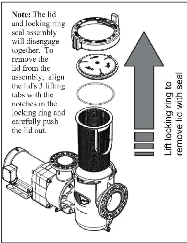
Figure 10. Exploded View of Pump
3.6 Pressure Testing, Strainer Pot
Certain local codes require that the circulation system be pressure tested with a proof pressure before being commissioned into service or before allowing construction to progress to the next stage.
WARNING
This strainer pot is intended to operate on the suction side of the pump and must not be installed on the pressure side of a circulation system. Extreme caution should be taken when applying pressure to this product during a system pressure test. Exceeding the pressure or temperature rating during the pressure test can result in a structural failure. A structural failure of the strainer pot assembly can cause the instantaneous release of energy causing failed components to be accelerated to high velocities and to travel distances of 30.5 m (100 feet) or more. These components could cause severe personal injury or death if they were to strike a person.
WARNING
It is important that the lid and locking ring are in the closed position before performing a pressure test. Instructions engraved on the locking ring show the locked position when the ports are in line with the arrows with the word "port" engraved on the locking ring. If the lid and locking ring are not installed and in the correct position a structural failure can occur causing sever personal injury or death.
WARNING
Improperly pressure testing a circulation system can involve significant risk of property damage or severe personal injury or death. Circulation systems store energy when pressure tested due to the elastic nature of the materials used in construction and due to the compressibility of air that may be contained in the system. The instructions below should be considered a guide only. Each installation should be considered a unique situation that should be carefully investigated for risk.
WARNING
Never test this equipment with air pressure even if specified by the local code. Even low levels of air pressure result in tremendous storage of energy that can instantaneously be released if a system failure occurs. This instantaneous release of energy can cause failed components to be accelerated to high velocities and to travel distances of 30.5 m (100 feet) or more. These components could cause severe personal injury or death if they were to strike a person.
- Understand the local code. The intent of the code may be to ensure that the piping system with its many bonded joints is leak free. Piping systems typically have a higher pressure capability than the other system components such as the pump or filter. Do not pressure test this product unless the code specifically requires this.
- Verify that each component in the system is designed to meet the local code test pressure. Most components should be marked with a maximum operating pressure. If a component is not marked consult the Owner's Instructions that came with the component or consult the manufacturer.
WARNING
When pressure testing a system with water, air is often trapped in the system during the filling process. This air will compress when the system is pressurized. Should the system fail, this trapped air can propel debris at a high speed and cause injury. Every effort to remove trapped air must be taken, including opening the bleed valve on the filter and loosening the pump basket lid while filling the pump.
WARNING
Trapped air in the system can cause the filter lid to be blown off, which can result in death, serious injury, or property damage. Be sure all air is properly purged out of the system before operating. DO NOT USE COMPRESSED AIR TO PRESSURE TEST OR CHECK FOR LEAKS.
WARNING
ELECTRICAL SHOCK HAZARD
Do not pressure test above 35 PSI. Pressure testing must be done by a trained pool professional. Circulation equipment that is not tested properly might fail, which could result in severe injury or property damage.
WARNING
When pressure testing the system with water, it is very important to make sure that the pump basket lid is completely secure.
- Fill the system with water to eliminate trapped air.
- Pressurize the system with water to no more than 35 PSI.
- Close the valve to seal the water in the system.
- Observe the system for any leaks or pressure decay.
- If there are lid leaks, repeat this procedure. For Jandy Technical Support, call 800.822.7933
Section 4. Jandy JCP Pump Operation

CAUTION
Never run the pump without water. Running the pump "dry" for any length of time can cause severe damage to both the pump and motor and may void the warranty.

WARNING
To avoid risk of property damage, severe personal injury or death, verify that all power is turned off before starting this procedure.
If this is a new pool installation, make sure all piping is clear of construction debris and has been properly pressure tested. The filter should be checked for proper installation, verifying all connections and clamps are secure according to the manufacturer's recommendations.
- Release all pressure from the system and open the filter pressure release valve.
- Depending on the location of the pump, do one of the following:
• If the pump is located below the water level of the pool, remove the plug in the strainer pot lid or remove the filter pressure relief valve to prime the pump with water.
• If the pump is located above the water level of the pool, remove the lid and fill the basket with water before starting the pump.
- Prior to replacing the lid, check for debris around the lid O-ring seat. Debris around the lid O-ring seat will cause air to leak into the system and will make it difficult to prime the pump.
- Hand-tighten the lid to make an air tight seal. Do not use any tools to tighten the lid: hand-tighten only. Make sure all valves are open and the flange bolts are tight.
- Restore power to the pump. Then turn on the pump.
- Confirm direction of motor rotation matches the directional arrow on the pump. Failure to do so may cause pump failure, and may also void warranty. Check wiring diagram to determine if motor can be wired to rotate in both directions.
- Once all the air has left the filter, close the pressure release valve.
- The pump should prime within ten minutes. The time it takes to prime will depend on the elevation and length of pipe used on the suction supply pipe.
- If the pump does not prime and all the instructions to this point have been followed, check for a suction leak. If there is no leak, repeat Steps 2 through 7.
For technical assistance, call Jandy Technical Support at 800.822.7933.
4.1 Priming
Fill the strainer pot with water before starting. This may be done through the 1/4" NPS threaded port in the top of the lid, or by removing the lid and locking ring. This is necessary to allow pump to prime and to prevent permanent damage. Except in freezing weather always keep liquid in the pump. No further lubrication of the pump end is necessary including the seal assembly. If flow does not start within ten minutes, stop motor and determine cause. Be sure all suction and discharge valves are open when the pump is running. Operating the pump with a closed valve in the system will cause pump damage.
Section 5. Maintenance and Storage
5.1 Maintenance
CAUTION
A misaligned basket will cause the lid to be improperly seated, allowing an air leak, which could result in pump damage.
The strainer built into the pump should be inspected and cleaned daily. These strainers are easy to clean. Follow the instructions printed on the locking ring.
- Remove the lid's center plug and seal.
- Turn the locking ring counter-clockwise until the lid and locking ring come free from the strainer pot.
- Inspect the lid O-ring for damage and replace if necessary.
- Remove the basket and clean.
- Install the lid and locking ring by turning clockwise until the arrows printed on the locking ring align with the pump inlet and outlet ports. When properly locked, the locking ring should click into place and the handles should be perpendicular to the pump ports.
- Install the lid's center plug and seal.
- The electric motor has sealed bearings and requires no lubrication maintenance.
5.2 Storage
CAUTION
The pump must be protected when freezing temperatures are expected. Allowing the pump to freeze will cause severe damage and may void the warranty.
CAUTION
Do not use antifreeze solutions in the pool, spa, or hot tub systems! Antifreeze is highly toxic and may damage the circulation system. The only exception to this is Propylene Glycol. For more information, see your local pool/spa supply store or contact a qualified swimming pool service company.
If the pool is deactivated for an extended period of time, care must be taken to protect the pump and motor from damage and ex posure. If storage is necessary for an extended period, place the motor and impeller assembly in a warm, dry location.
NOTE: Make sure power is turned off at the control panel. Drain the pump by removing both drain plugs. Disconnect the suction and discharge lines at the flange connections, then move unit to warm, dry indoor location.
When activating the pump again, reverse the above procedures. Replace the O-ring between the strainer pot and pump housing if damaged. Install drain plugs. Check the pump shaft for free movement. Prime the pump as above and check the rotation of pump shaft.
Section 6. Servicing
6.1 Required Tools
- Tape Measure
- Level
- Gloves
- Eye Protection
• Silicon O-ring Lubricant - Multimeter
- Amp Meter
- Wire Strippers
- Torque Wrench
- 1/4" Nut Driver
- 5/16" Nut Driver
- Flat Head Screwdriver
- Hammer
• 15/16" Box End Wrench/Socket
• 9/16" Box End Wrench/Socket - 7/16" Box End Wrench/Socket
- 3/4" Socket Wrench
• 5/16" Allen Wrench
6.2 Replacement Parts
This unit is designed to provide maximum electrical safety. To assure continued protection against shock hazard use only identical factory supplied replacement parts when servicing.
6.3 Alternate Parts
The Jandy JCP series pump was designed with commonly sized hardware, seals, and NEMA JM frame motors. A comprehensive list of materials can be found in the "Parts List" section of this manual and contains general descriptions of all fasteners, seals, and motors needed to assemble the pump properly.
- Shaft Seal: The JCP series pump was designed to use a 1-1/4" type 2100 or Type 21 mechanical seal with a spring working length of 1.062 inches and ceramic height of 0.436 inches.
-
Motors: The JCP series pump uses industry standard NEMA JM frame motors for maximum versatility. It is recommended that you replace the motor with the Jandy replacement motor as identified in the Replacement Parts section. Any motor purchased as an alternate for the JCP series pumps must have identical electrical ratings, compliance certifications, duty ratings, and must be equipped with a Jandy stainless steel shaft sleeve.
-
Fasteners: Jandy has made every effort to utilize standard stainless steel hardware in the JCP series pump. Most fasteners are SAE and of common size, length, and thread pitch. If you are replacing the Jandy factory fastener, please make sure it is identical in size, thread, head size, etc.
- Other Pump Components: In order to maintain peak performance of your pump, Jandy highly recommends only using genuine factory replacement parts. Do not use parts from other pump brands or generic parts, unless they are referenced in this manual.
6.4 Pump Disassembly
WARNING
This pump must be serviced by a professional service technician qualified in pool/spa installation. The following procedures must be followed exactly. Improper installation and/or operation can create dangerous electrical hazards, which can cause high voltages to run through the electrical system. This can cause property damage, serious personal injury, and/or death. Improper installation and/or operation may void the warranty.
WARNING
Zodiac Pool Systems LLC requires that a qualified service technician or electrician properly disconnect the electrical wiring at the pump motor.
WARNING
ELECTRICAL SHOCK HAZARD
Turn off all switches and the main breaker in the pump's electrical circuit before starting the procedure. Wait five (5) minutes after power is disconnected before opening motor. Failure to comply may cause a shock hazard, resulting in severe personal injury or death.
- Turn off the pump. Switch off the circuit breaker to the pump motor.
- Wait 5 minutes before opening the wiring compartment and disconnecting the power source from the pump. Zodiac Pool Systems LLC requires that a qualified service technician or electrician properly disconnect the electrical wiring at the pump motor.
- Close all necessary valves to prevent pool water from reaching the pump. Remove the drain plugs and o-rings to drain the water from the pump.
- Remove the flange bolts and washers from the inlet and outlet connections. Remove the fasteners holding the pump to the pad. Slide the pump away from the plumbing.

WARNING
Due to the potential risk of fire, electric shock, or injuries to persons, Jandy Pumps must be installed in accordance with the National Electrical Code® (NEC®), all local electrical and safety codes, and the Occupational Safety and Health Act (OSHA). Copies of the NEC may be ordered from the National Fire Protection Association, 1 Batterymarch Park, Quincy, MA, USA 02169-7471, or obtained from your local government inspection agency. In Canada, Jandy Pumps must be installed in accordance with the Canadian Electrical Code (CEC®).
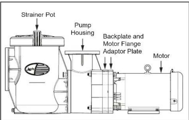
Figure 11. JCP Pump with Strainer Pot Assembly
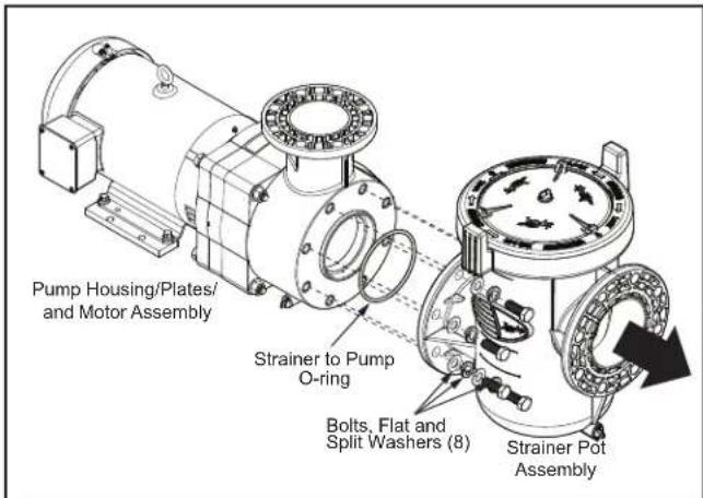
Figure 12. Remove Strainer Pot from Pump Assembly
- Using a 15/16" wrench, loosen the eight (8) 5/8" Hex Screws securing the Strainer Pot assembly to the pump housing/motor body. See Figures 11 and 12.
- Pull the Strainer Pot assembly forward from the Pump Housing/Plates/Motor assembly, as shown in Figure 12.
- Remove the Strainer to Pump O-ring on the front of the Pump Housing. See Figure 12.
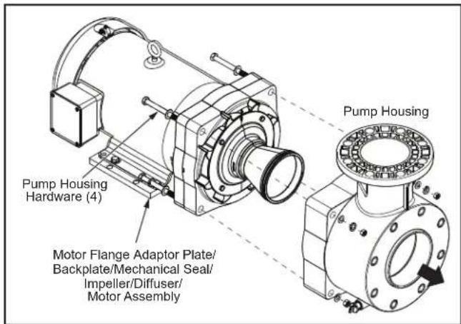
Figure 13. Remove Pump Housing
- Using a 15/16" wrench, loosen the four (4) Hex Screws of the Pump Housing Hardware securing the Pump Housing to the Motor/ Motor Flange Adapter Plate/Backplate/Mechanical Seal/Impeller/ Diffuser assembly. See Figure 13.
- Carefully pull the Pump Housing forward away from motor assembly. Ensure the Diffuser clears the pump housing during this process. See Figure 13.
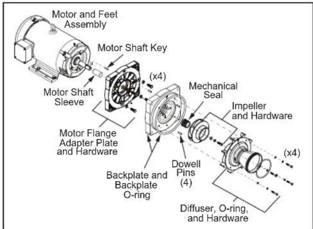
Figure 14. Remove Mechanical Seal, Impeller, Diffuser and Motor Accessories
- Using a 7/16 wrench, loosen the four (4) Hex Screws securing the Diffuser to the Backplate. Carefully pull off the Diffuser and remove the Diffuser O-ring. See Figure 14.
- Hold the impeller while using a 5/16" Allen key to remove the impeller bolt by turning counter clockwise.
IMPORTANT NOTE: Do not insert a tool into the impeller vanes to hold the impeller. That will damage or even destroy the impeller vanes. Hold the impeller by hand or use a strap wrench.
- Pull the impeller and drive shaft key carefully off of the drive shaft. Be careful not to lose the drive shaft key.
-
Pull off the backplate O-ring and inspect for damage.
-
Remove the carbon face seal half from the motor shaft. This is a spring loaded seal. Grasp the portion of the seal closest to the impeller body and pull the seal off using a twisting motion.
- Using two flat head screwdrivers, insert the ends into the two side openings between the backplate and the motor flange adapter plate. Slowly and evenly leverage the backplate forward. Take care not to damage the ceramic side seal.
- For motors with a NEMA 182-184 JM frame, use a 9/16" socket wrench to loosen the four (4) hex screws securing the motor flange adapter plate to the motor. For NEMA 213-215 JM frames, use a 3/4" socket wrench. Carefully pull away the motor flange adapter plate avoiding any impact to the motor shaft and set aside. See Figure 14.
6.5 Pump Assembly
- Attach the motor flange adapter plate to the motor assembly using the four sets of hardware (hex screws, split washers, and flat washers). The flange adapter plate is marked "TOP" to show the correct orientation. Ensure the motor drive shaft is not impacted during this operation.
- Verify the two (2) dowel pins are inserted to assist with aligning the Backplate.
- Align the backplate with the mating alignment pins in the adapter plate and with the front faced arrow pointing downward. Push the backplate onto the alignment pins until the back surface is flush with the adapter plate. Lightly tap on the backplate front face with a soft hammer or mallet if necessary.
- Install the ceramic seal side by lubricating the seal and cup with distilled water and soap solution. Press the seal evenly and firmly down into the seal pocket by hand. Do not use O-ring lubricant to install this seal. Do not use any tools to press the seal into the pocket. Clean the surface of the ceramic with a nonabrasive cloth. Before installing the spring seal, ensure the surface of the ceramic is free of cracks, chips, and debris. If any damage is observed, replace immediately.
- Install the spring seal side by lubricating with distilled water and soap solution. Do not use O-ring lubrication to install this seal. Do not use any tools to install this seal. Ensure the carbon side of the seal is facing the ceramic side and the rubber side is facing the impeller. By hand, slowly press the seal onto the drive shaft sleeve until the two seal surfaces nearly touch. The seal should be uncompressed and hanging over the end of the motor's drive shaft sleeve slightly.
-
Install the shaft key into the motor drive shaft slot. Align the impeller's keyway with the drive shaft key. Press the impeller onto the drive shaft. Secure the impeller with the hex socket screw, split washer, and flat washer. Slowly turn clockwise to tighten the screw until tight. The impeller will slowly press the two seal faces together and compress the spring seal into the proper position.
-
Attach the diffuser by aligning the arrow on the diffuser's front face with the arrow on the backplate. The diffuser should press onto the two alignment pins located in the backplate. Secure the diffuser using the hex bolts, split washer, and flat washer. Place the diffuser O-ring into the groove around the inlet. Ensure the O-ring is not damaged or twisted during installation. Silicon O-ring lubrication may be placed on the O-ring to assist with assembly of the pump housing.
- Install the backplate O-ring. Ensure it is not twisted. Silicon O-ring lubrication may be placed on the O-ring to assist with assembly of the pump housing.
- Slide the Pump Housing onto the Motor Assembly and secure with the four (4) sets of hardware (hex screws, split washers, flat washers, and nuts). Ensure the split washers are placed under the hex nut..
- Tighten the bolts lightly in a crossing "X" pattern using a 15/16" wrench to draw the backplate to the body in an even manner. Once all the bolts are snug, tighten in the same order to 20 ft-lbs of torque.
- Secure the Strainer Pot Assembly onto the assembled Pump Housing with motor using the eight (8) hex screws, split washers and flat washers.
Tighten the bolts lightly in a crossing “X” pattern using a 15/16” wrench starting with the inner (middle) four (4) and then the outer (top and bottom) four (4) to draw the backplate to the body in an even manner. Once all the bolts are snug, tighten in the same order to 20 ft-lbs of torque.
- If the pump is located above the water level of the pool, remove the lid and fill the basket with water before starting the pump. See "Strainer Pot Service" section for details.
NOTE To avoid leaks in system, check for debris around lid O-ring seat prior to replacing lid.
WARNING
If any valves have been previously closed, reposition each valve to avoid closure to the pump's discharge also known as "Dead Heading". Trapped air in the system can cause the filter lid to be blown off. This can result in death, serious personal injury, or property damage. Be sure all air is out of the system before operating.
- Hand-tighten the lid to make an air tight seal. Do not use any tools to tighten the lid.
- Ensure all drain plugs are installed and hand tight.
IMPORTANT NOTE: Failure to remove the lid's center plug before service will significantly increase the difficulty of assembling or disassembling the lid and may cause the lid's lifting tabs to break.
Section 7. Troubleshooting and Repair
Jandy strongly recommends that you call a qualified service technician to perform any repairs on the filter/pump system. To locate a qualified technician, visit jandy.com or jandy.ca.
NOTE: Never work on pump without making certain power is off.
| Symptom Possible | Cause Solution | |
| Pump will not prime | Suction air leak. | Ensure all flange bolts are tightened properly and the gaskets are positioned centrally on the flange. Verify the plumbing is level and flange connections are parallel to each other. Ensure the strainer pot lid is installed correctly and the O-ring is free of tears and all debris. If necessary, clean the O-ring with soapy water or replace. Inspect the lid for cracks. Make sure all drain plugs are tight. |
| No water in pump or strainer. | Ensure the strainer pot is either installed on the pump inlet or the outlet plumbing from the strainer is on the same level as the inlet to the pump. The JCP pump is not a self priming pump unless the strainer pot is included on the suction side. The strainer must not be installed below grade of the pump. When filling the strainer pot with water, fill until the water level reaches the inlet plumbing. In flooded suction cases, the strainer may be filled higher to minimize the amount of air in the strainer pot when the pump starts. Ensure the pool water level is not below the skimmer. | |
| Closed valves or blocked lines. | Open all valves in the system. Clean the skimmer and pump strainer baskets. Open the pump and check for debris inside the impeller. | |
| Pump is too high above pool | The pump must not be more than 10ft above the pool surface. If possible, reduce the height of the pump from the surface of the water. The higher the pump is installed above the surface, the longer it will take to prime. Priming to heights of 10 ft may take up to 10 minutes. If the pump does not prime within 45 minutes, check for inlet plumbing leaks. | |
| Pump is too far away from pool | Check the distance from the pool and ensure a check valve is in place for long distance inlet plumbing. Check valves will keep the inlet plumbing filled with water when the pump is not operating. | |
| Pump spinning backwards | The proper rotation for the pump is clockwise-lead end. Ensure the motor is spinning in the same direction as indicated on the rotation labels located on the pump and motor. The motor rotation can be reversed by switching any 2 line leads for three phase motors. For single phase motors that can rotate in both directions, refer to the motor's wiring diagram. | |
| Motor does not turn | No power to motor. | Verify all breakers are on and not in the overload position. If the pump is being controlled by a VFD, ensure the controller is on and giving power to the motor. |
| Thermal protector tripped | Check the temperature of the motor, if the motor is hot the thermal protector may have turned the motor off. | |
| The motor is improperly connected | Check the wiring diagram and verify the configuration needed for the power source. | |
| Drive shaft seized | With all power off to the motor, turn the motor's drive shaft manually. The drive shaft should spin freely by hand without catching or dragging. If the drive shaft does not spin freely, disassemble the pump and repair. | |
| Low flow | Dirty filter. Clean filters when the back pressure is high. | |
| Dirty skimmer basket. | See problem 1. | |
| Suction air leak. | ||
| Closed valves or blocked lines. | ||
| Pump spinning backwards | ||
| Motor runs hot | Low voltage or incorrect voltage. | Have a certified electrician check the voltage at the motor. The voltage at the motor must be within 10% of the nameplate voltage. If the voltage is outside of this range, contact the local power provider. |
| Incorrect wiring, phase unbalance | Verify the wiring diagram matches the configuration used for the power supply. Verify current on all phases are nearly identical. If a phase current is notably higher than the others, the motor is operating with phase unbalance. Turn off the motor and check the wiring connections for frayed, broken, or partial conductor connections. Cut and restrip leads if necessary. Verify voltage between each phase. The voltage variation between phases should be no larger than 5%. If the connections are secure, phase voltage is similar, and a phase unbalance is still present, the motor winding insulation may be damaged and the motor must be repaired or replaced. | |
| Undersized wire Increase the wire gauge for all leads going to the motor. | ||
| Installed in direct sun. It is best to keep the pump sheltered from direct sunlight. | ||
| Poor ventilation. | Do not enclose the pump in a small location with minimal free air flow. Make sure that there is adequate room around the motor to circulate air and keep the motor cool. | |
| Noisy motor | Bad bearings. Have a certified technician replace the bearings. | |
| Rotor strikes Have a certified technician check the rotor. | ||
| Debris in fan shroud | With the power turned off, remove the motor's fan cover and clean out any debris that may have become trapped inside. Inspect the fan for damage. If the fan is damaged or blades are missing, replace the fan immediately. An unbalanced fan load can cause bearing damage. | |
| Noisy pump | Suction air leak See problem 1. | |
| Restricted suction line due to blockage or under-sized pipe. High vacuum reading at pump suction. | Clean the skimmer and pump strainer baskets. Inspect piping for further blockages. Ensure all valves on the suction side of the pump are fully open. The minimum pipe diameter for the inlet of all JCP pumps is 6 inches. | |
| Debris in pump impeller | Disassemble the pump and check for gravel, sticks, leaves, plaster, or any other foreign objects that may be clogging the impeller. Fine debris may also be located between the impeller and diffuser on the snout of the impeller. | |
| Pump spinning backwards See problem 1. | ||
| Cavitation | Improve the suction conditions of the pump. Increase plumbing size, reduce the number of 90 degree fittings. Increase the backpressure on the pump by closing a valve on the pump outlet. Reduce the suction lift distance. | |
| If issues persist, contact Jandy Technical Support at 1.800.822.7933 | ||
Section 8. Replacement Parts List
The grouping of parts illustrations cover all Jandy JCP Pump models. The table on page 18 indicates the name of each part. Should you need a replacement, refer to the drawing below – locate the part that matches your pump parts. Contact your local Jandy supplier with the Key Number and Description of the parts required, along with your pump Model number, Spec. Number and Serial number, which are located on the pump nameplates.
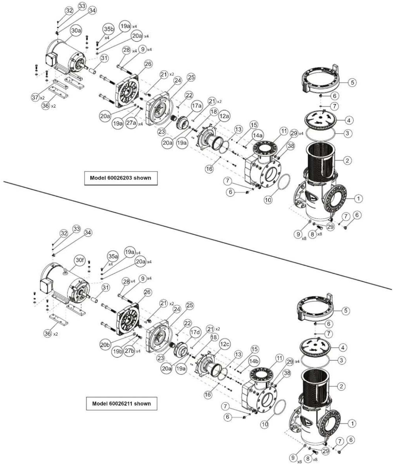
For a complete list of replacement parts, please visit www.Jandy.com or contact Jandy Technical Support at 1.800.822.7933 or email productsupport@fluidra.com.
| JCP KEY NUMBERS | |||
| Key Number | Description HP Size Qty | ||
| 1 | Strainer Pot All 1 | ||
| 2 | Strainer Basket All 1 | ||
| 3 | O-ring, Strainer Pot Lid, 8 x 265mm All 1 | ||
| 4 | Lid, Clear All 1 | ||
| 5 | Locking Ring All 1 | ||
| 6 | Drain Plug All 3 | ||
| 7 | O-ring, Drain Plug, #2-112 All 3 | ||
| 8 | Hex Screw, 5/8"- 11 x 1-3/4" All 8 | ||
| 9 | Flat Washer, 11/16" x 1-5/16" x 0.78" All 8 | ||
| 10 | O-ring, Strainer to Pump, 1/4" x 5-7/8", Dash No 436 All 1 | ||
| 11 | Pump Housing | All 1 | |
| 12a | Diffuser, 5-7.5 HP | 5, 7.5 | 1 |
| 12b | Diffuser, 10 HP | 10 1 | |
| 12c | Diffuser, 15 HP | 15 1 | |
| 13 | O-ring, Diffuser, 3/16" x 4-7/8", Dash No 352 | All 1 | |
| 14a | Hex Screw, Diffuser, 1/4"-20 x 1-1/2" | 5, 7.5, 10 | 4 |
| 14b | Hex Screw, Diffuser, 1/4"-20 x 1-3/4" | 15 4 | |
| 15 | Split Washer, 1/4" | All 4 | |
| 16 | Flat Washer, 1/4" x 1/2" x 0.057" | All 4 | |
| 17a | Impeller, 5.0 HP | 5 | 1 |
| 17b | Impeller, 7.5 HP | 7.5 | 1 |
| 17c | Impeller, 10.0 HP | 10 1 | |
| 17d | Impeller, 15.0 HP | 15 1 | |
| 18 | Hex Socket Screw, Impeller, 3/8"-16 x 1" | All 1 | |
| 19a | Split Washer, 3/8" | All | 9 or 5 |
| 19b | Split Washer, 1/2" | 7.5, 10, 15 | 4 |
| 20a | Flat Washer, 3/8" | All | 9 or 5 |
| 20b | Flat Washer, 1/2" | 7.5, 10, 15 | 4 |
| 21 | Dowel Pin, 5/16" x 1" | All 4 | |
| 22 | Key, Shaft, Motor | All 1 | |
| 23 | Mechanical Seal, Assembly, 1/4" Type 2100 | All 1 | |
| 24 | Backplate | All 1 | |
| 25 | O-ring, Backplate, 3/8" x 10" | All 1 | |
| 26 | Motor Flange Adapter Plate | All 1 | |
| 27a | Hex Screw, 3/8"-16 x 1" | 5 | 4 |
| 27b | Hex Screw, 1/2"-13 x 1-1/4" | 7.5, 10, 15 | 4 |
| 28 | Hex Screw, 5/8"-11 x 7" | All 4 | |
| 29 | Split Washer, 11/16" | All | 4 or 12 |
| 30a | Motor, 5.0 HP - 3 PH 5 1 | ||
| 30b | Motor, 5.0 HP - 1 PH 5 1 | ||
| 30c | Motor, 7.5 HP - 3 PH 7.5 1 | ||
| 30d | Motor, 7.5 HP - 1 PH 7.5 1 | ||
| 30e | Motor, 10.0 HP - 3 PH 10 1 | ||
| 30f | Motor, 15.0 HP - 3 PH 15 1 | ||
| 31 | Shaft Sleeve, 1" x 1-1/4" x 2.36" All 1 | ||
| 32a | Hex Screw, #10-32 x 1/2" TEFC Motor 1 | ||
| 32b | Hex Screw, #10-32 x 1/2" Thread Cutting ODP Motor 1 | ||
| 33 | Star Washer, #10 All 1 | ||
| 34 | Bonding Lug, Dual Path | All 1 | |
| 35a | Hex Screw, 3/8"-16 x 3/4" | 7.5, 10, 15 | 4 |
| 35b | Hex Screw, 3/8"-16 x 1-1/2" | 5 4 | |
| 36 | Motor Support, 215JM Frame | All 2 | |
| 37 | Motor Support, 184JM Frame | 5 2 | |
| 38 | Nut, Brass, 5/8"-11 | All 4 | |
8.1 JCP R-Kit List
For a complete list of replacement parts, please visit www.Jandy.com or contact Jandy Technical Support at 1.800.822.7933 or email productsupport@fluidra.com.
| JCP R-KIT LIST | ||||
| R-kit Item | Part Number Description | Key Number Qty | ||
| 1 R092 | 0400 Motor, 5.0HP, 3-Phase | 30a 1 | ||
| 36 | 2 | |||
| 37 | 2 | |||
| 35b 4 | ||||
| 19a 4 | ||||
| 20a 4 | ||||
| 31 | 1 | |||
| 22 | 1 | |||
| 32 | 1 | |||
| 33 | 1 | |||
| 34 | 1 | |||
| 2 R092 | 0500 Motor, 5.0HP, 1-Phase | 30b 1 | ||
| 36 | 2 | |||
| 37 | 2 | |||
| 35b 4 | ||||
| 19a 4 | ||||
| 20a 4 | ||||
| 31 | 1 | |||
| 22 | 1 | |||
| 32 | 1 | |||
| 33 | 1. | |||
| 34 | 1 | |||
| 3 R092 | 0600 Motor, 7.5HP, 3 Phase | 30c 1 | ||
| 36 | 2 | |||
| 35a 4 | ||||
| 19a 4 | ||||
| 20a 4 | ||||
| 31 | 1 | |||
| 22 | 1 | |||
| 32 | 1 | |||
| 33 | 1 | |||
| 34 | 1 | |||
| 4 R092 | 0700 Motor, 7.5HP, 1 Phase | 30d 1 | ||
| 36 | 2 | |||
| 35a 4 | ||||
| 19a 4 | ||||
| 20a 4 | ||||
| 31 | 1 | |||
| 22 | 1 | |||
| 32 | 1 | |||
| 33 | 1 | |||
| 34 | 1. | |||
| R-kit Item | Part Number Description | on Key Number Qty | ||
| 5 R092 | 0800 Motor, 10.0HP, 3 | Phase | 30e 1 | |
| 36 | 2 | |||
| 35a 4 | ||||
| 19a 4 | ||||
| 20a 4 | ||||
| 31 | 1 | |||
| 22 | 1 | |||
| 32 | 1 | |||
| 33 | 1 | |||
| 34 | 1 | |||
| 6 R092 | 0900 Motor, 15.0HP, 3 | Phase | 30f 1 | |
| 36 | 2 | |||
| 35a 4 | ||||
| 19a 4 | ||||
| 20a 4 | ||||
| 31 | 1 | |||
| 22 | 1 | |||
| 32 | 1 | |||
| 33 | 1 | |||
| 34 | 1. | |||
| 7 R092 | 1000 Motor Flange Adapter Plate | 26 | 1 | |
| 21 | 2 | |||
| 8 R092 | 1100 Backplate with Seals Kit | 24 | 1 | |
| 23 | 1 | |||
| 25 | 1 | |||
| 21 | 2 | |||
| 9 R092 | 1200 Impeller and Hardware Kit, 5HP | 17a 1 | ||
| 20a 1 | ||||
| 19a 1 | ||||
| 18 | 1 | |||
| 22 | 1 | |||
| 10 R092 | 1300 Impeller and Hardware Kit, 7.5HP | 17b 1 | ||
| 20a 1 | ||||
| 19a 1 | ||||
| 18 | 1 | |||
| 22 | 1 | |||
| 11 | R0921400 | Impeller and Hardware Kit, 10HP | 17c | 1 |
| 20a 1 | ||||
| 19a 1 | ||||
| 18 | 1 | |||
| 22 | 1 | |||
| 12 R09 | 21500 Impeller and Hardware Kit, 15HP | 17d 1 | ||
| 20a 1 | ||||
| 19a 1 | ||||
| 18 | 1 | |||
| 22 | 1 | |||
| 13 R09 | 21600 Diffuser and Hardware Kit, 5-7.5HP | 12a 1 | ||
| 14a 4 | ||||
| 15 | 4 | |||
| 16 | 4 | |||
| 13 | 1 | |||
| 14 R09 | 21700 Diffuser and Hardware Kit, 10HP | 12b 1 | ||
| 14a 4 | ||||
| 15 | 4 | |||
| 16 | 4 | |||
| 13 | 1 | |||
| 15 R09 | 21800 Diffuser and Hardware Kit, 15HP | 12c 1 | ||
| 14b 4 | ||||
| 15 | 4 | |||
| 16 | 4 | |||
| 13 | 1 | |||
| 16 R09 | 21900 Pump Housing Kit | 11 1 | ||
| 25 | 1 | |||
| 10 | 1 | |||
| 6 | 1 | |||
| 7 | 1 | |||
| 17 R09 | 22000 Motor Flange Adapter Plate Hardware, 215JM | 27b 4 | ||
| 20b 4 | ||||
| 19b 4 | ||||
| 18 R09 | 22100 Motor Flange Adapter Plate Hardware, 184JM | 35a 4 | ||
| 20a 4 | ||||
| 19a 4 | ||||
| 19 R09 | 22200 | Pump Housing Hardware Kit | 28 | 4 |
| 9 | 8 | |||
| 29 | 4 | |||
| 38 | 4 | |||
| 20 R09 | 22300 | Strainer Pot | 1 | 1 |
| 6 | 1 | |||
| 7 | 1 | |||
| 21 R09 | 22400 | Strainer Basket 2 1 | ||
| 22 R09 | 22500 | Lid and Locking Ring Kit | 5 | 1 |
| 4 | 1 | |||
| 3 | 1 | |||
| 6 | 1 | |||
| 7 | 1 | |||
| 23 R09 | 22600 Strainer Pot Hardware Kit | ware Kit | 8 | 8 |
| 9 | 8 | |||
| 29 | 8 | |||
| 24 R09 | 22700 JCP Pump Seals | Kit | 25 | 1 |
| 13 | 1 | |||
| 3 | 1 | |||
| 10 | 1 | |||
| 7 | 3 | |||
| 25 R09 | 22800 Dowel Pin Kit 21 | 4 | ||
| 26 R09 | 22900 Strainer Pot Assembly O-ring Kit 10 1 | |||
| 27 R09 | 23000 Mechanical Seal Kit 23 1 | |||
| 28 R09 | 23100 | Strainer Pot Lid O-ring Kit 3 1 | ||
| 29 R09 | 23200 | Diffuser O-ring Kit 13 1 | ||
| 30 R09 | 23300 | Backplate O-ring Kit 25 1 | ||
| 31 R09 | 23400 | Shaft Sleeve Kit 31 1 | ||
| 32 R09 | 23500 | Bonding Lug Kit | 32 | 1 |
| 33 | 1 | |||
| 34 | 1 | |||
| 33 R04 | 46000 | Drain Plug Kit | 6 | 2 |
| 7 | 2 | |||
Section 9. Product Dimensions

Figure 15. Pump Without Strainer Pot Dimensions
Pump Without Strainer Pot
| SKU Number A B C | Ship Weight (lb) | Ship Dimension | ||
| JCP05-1CT-N 26-1/4" 16" | 12-1/2" | 138 | 33" x 24" x 25.25" | |
| JCP07-1BD-N 25" 17" | 13-1/2" | 157 | ||
| JCP05-3AT-N 24-3/4" 16" | 12-1/2" | 129 | ||
| JCP07-3AT-N 26-1/2" 17" | 13-1/2" | 161 | ||
| JCP10-3AT-N 26-1/2" 17" | 13-1/2" | 169 | ||
| JCP15-3AT-N 29" 17" | 13-1/2" | 209 | ||
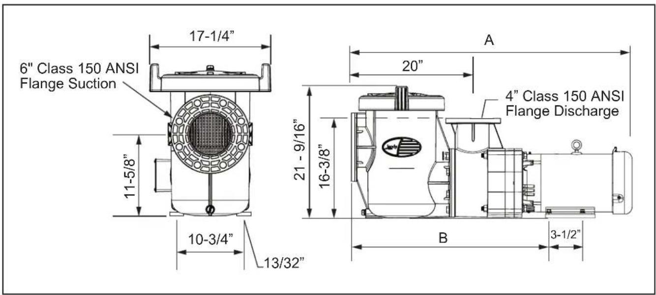
Figure 16. Pump With Strainer Pot Dimensions
Pump With Strainer Pot
| SKU Number A B | C | Ship Weight (lb) | Ship Dimension | ||
| JCP05-1CT-S 43-1/4" 33" | 12-1/2" | 178 | 48" x 24" x 28" | ||
| JCP07-1BD-S 42" 34" | 13-1/2" | 197 | |||
| JCP05-3AT-S 41-3/4" 33" | 12-1/2" | 169 | |||
| JCP07-3AT-S 43-1/2" 34" | 13-1/2" | 201 | |||
| JCP10-3AT-S 43-1/2" 34" | 13-1/2" | 209 | |||
| JCP15-3AT-S 46" 34" | 13-1/2" | 249 | |||
Section 10. Product Specifications
10.1 Specifications
| SKU Number M | Motor HP S.F | Volts Ph | ase Hz Speed | |||
| JCP05-1CT-N 5 1.15 208-230 1 60 3450 | ||||||
| JCP07-1BD-N 7.5 1.15 | 230 | 1 60 3450 | ||||
| JCP05-3AT-N | 5 | 1.15 | 208-230/460 | 3 | 60 | 3450 |
| JCP07-3AT-N 7.5 1.15 | 208-230/460 | 3 60 3520 | ||||
| JCP10-3AT-N | 10.0 | 1.15 | 208-230/460 | 3 | 60 | 3510 |
| JCP15-3AT-N | 15.0 | 1.15 | 208-230/460 | 3 | 60 | 3500 |
| JCP05-1CT-S | 5 1.15 208-230 1 60 3450 | |||||
| JCP07-1BD-S | 7.5 1.15 | 230 | 1 60 3450 | |||
| JCP05-3AT-S | 5 | 1.15 | 208-230/460 | 3 | 60 | 3450 |
| JCP07-3AT-S | 7.5 | 1.15 | 208-230/460 | 3 | 60 | 3520 |
| JCP10-3AT-S | 10.0 | 1.15 | 208-230/460 | 3 | 60 | 3510 |
| JCP15-3AT-S | 15.0 | 1.15 | 208-230/460 | 3 | 60 | 3500 |
| SKU Number | Suction | Discharge | JM Frame | Ins | Inverter |
| JCP05-1CT-N | 6 | 4 | 184 | F | NO |
| JCP07-1BD-N | 6 | 4 | 213 | F | NO |
| JCP05-3AT-N | 6 | 4 | 184 | H | READY |
| JCP07-3AT-N | 6 | 4 | 213 | H | READY |
| JCP10-3AT-N | 6 | 4 | 215 | H | READY |
| JCP15-3AT-N | 6 | 4 | 215 | H | READY |
| JCP05-1CT-S | 6 | 4 | 184 | F | NO |
| JCP07-1BD-S | 6 | 4 | 213 | F | NO |
| JCP05-3AT-S | 6 | 4 | 184 | H | READY |
| JCP07-3AT-S | 6 | 4 | 213 | H | READY |
| JCP10-3AT-S | 6 | 4 | 215 | H | READY |
| JCP15-3AT-S | 6 | 4 | 215 | H | READY |
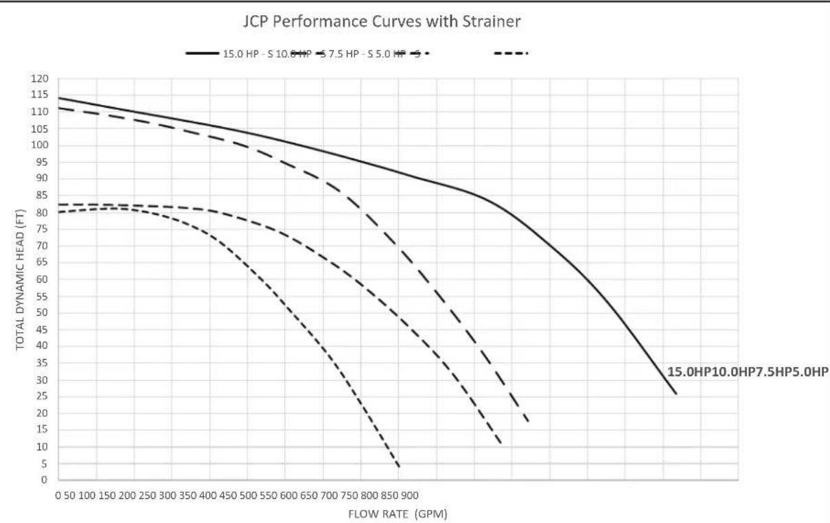
Section 11. Technical Data
For a complete list of replacement parts, please visit www.Jandy.com or contact Jandy® Technical Support at 1.800.822.7933 or email productsupport@fluidra.com.
line
| FLOW RATE (GPM) | 15.0 HP - S 10.8 HP | 15.0 HP - S 7.5 HP | 15.0 HP - S 5.0 HP | 15.0 HP - S 10.8 HP + S 7.5 HP + S 5.0 HP | | --------------- | ------------------- | ------------------ | ------------------ | ------------------------------------------ | | 0 | 115 | 112 | 110 | 80 | | 50 | 113 | 110 | 108 | 80 | | 100 | 111 | 108 | 106 | 80 | | 150 | 110 | 107 | 105 | 80 | | 200 | 109 | 106 | 104 | 80 | | 250 | 108 | 105 | 103 | 80 | | 300 | 107 | 104 | 102 | 80 | | 350 | 106 | 103 | 101 | 80 | | 400 | 105 | 102 | 100 | 80 | | 450 | 104 | 101 | 99 | 79 | | 500 | 103 | 100 | 98 | 78 | | 550 | 102 | 99 | 97 | 77 | | 600 | 101 | 98 | 96 | 76 | | 650 | 100 | 97 | 95 | 75 | | 700 | 99 | 96 | 94 | 74 | | 750 | 98 | 95 | 93 | 73 | | 800 | 97 | 94 | 92 | 72 | | 850 | 96 | 93 | 91 | 71 | | 900 | 95 | 92 | 90 | 70 | | >900 | ~25 | ~20 | ~15 | ~5 |Figure 17. Jandy JCP With Strainer Pump Curves
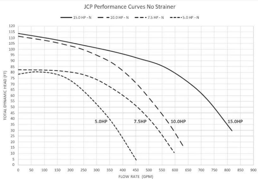
line
| FLOW RATE (GPM) | 15.0 HP - N | 10.0 HP - N | 7.5 HP - N | 5.0 HP - N | | --------------- | ----------- | ----------- | ---------- | ---------- | | 0 | 115 | 112 | 82 | 79 | | 50 | 113 | 110 | 81 | 78 | | 100 | 111 | 108 | 80 | 77 | | 150 | 109 | 106 | 79 | 76 | | 200 | 107 | 104 | 78 | 75 | | 250 | 105 | 102 | 77 | 74 | | 300 | 103 | 100 | 76 | 73 | | 350 | 101 | 98 | 75 | 72 | | 400 | 99 | 96 | 74 | 71 | | 450 | 97 | 94 | 73 | 70 | | 500 | 95 | 92 | 72 | 69 | | 550 | 93 | 90 | 71 | 68 | | 600 | 91 | 88 | 70 | 67 | | 650 | 89 | 86 | 69 | 66 | | 700 | 87 | 84 | 68 | 65 | | 750 | 85 | 82 | 67 | 64 | | 800 | 83 | 80 | 66 | 63 | | 850 | 81 | 78 | 65 | 62 | | 900 | 79 | 76 | 64 | 61 |Figure 18. Jandy JCP With No Strainer Pump Curves
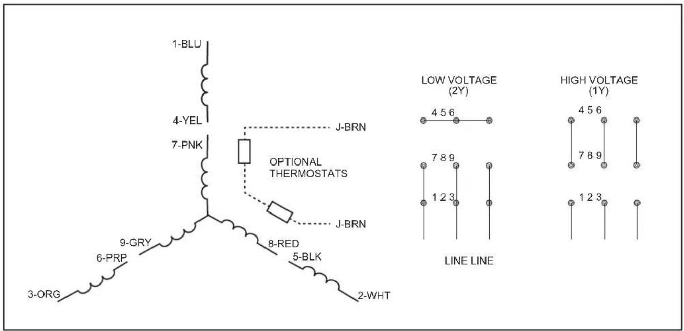
Figure 19. Jandy JCP Electrical Diagram - 5.0, 7.5, 10.0, 15.0 HP, 3-Phase
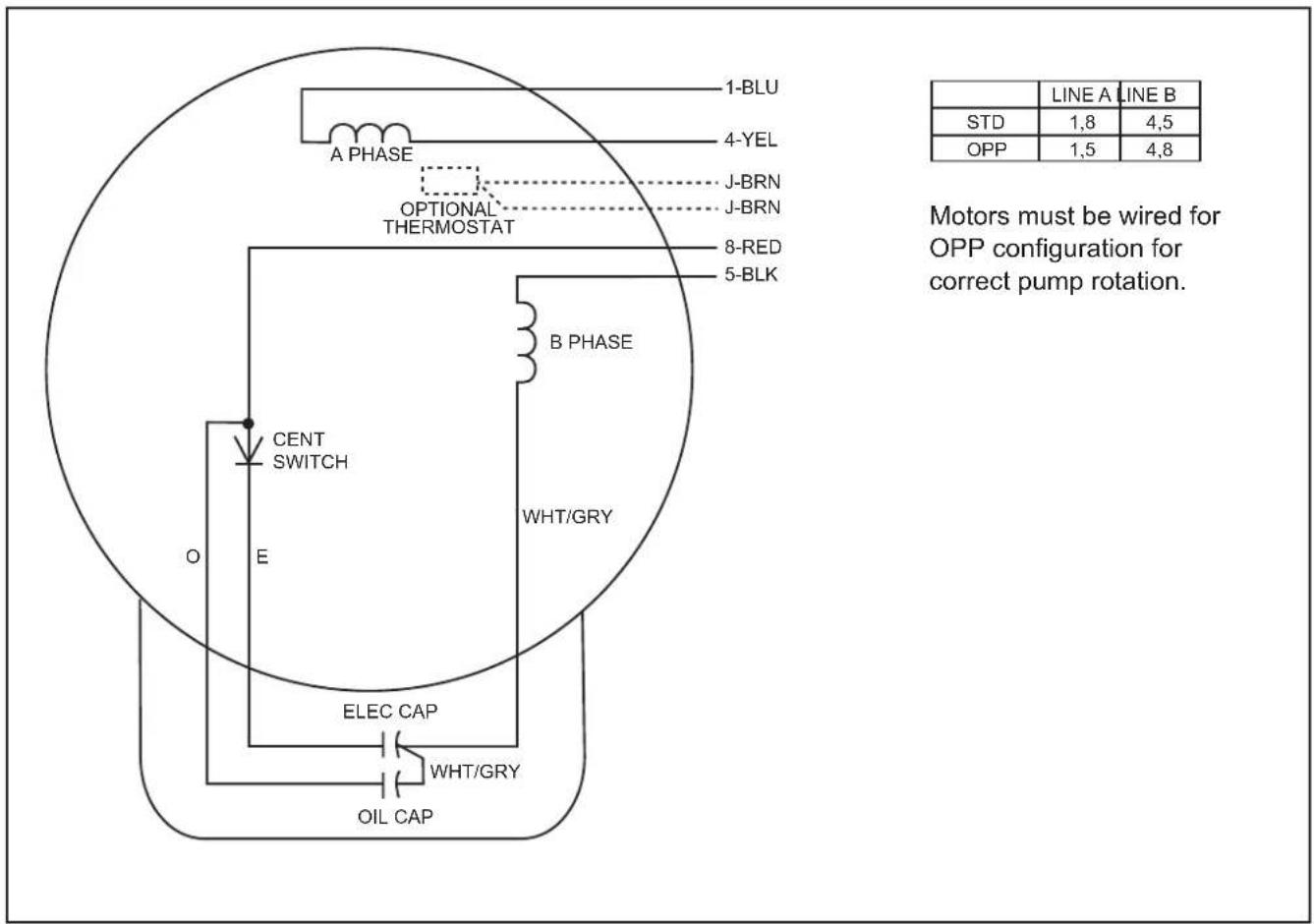
Figure 20. Jandy JCP Electrical Diagram - 5.0, 7.5 HP, 1-Phase
NOTES
NOTES
NOTES
Zodiac Pool Systems LLC
2882 Whiptail Loop # 100, Carlsbad, CA 92010
USA | Jandy.com | 1.800.822.7933
Zodiac Pool Systems Canada, Inc.
2-3365 Mainway
Burlington, ON L7M 1A6 Canada
1.888.647.4004 | www.ZodiacPoolSystems.ca
©2021 Zodiac Pool Systems LLC. All rights reserved. ZODIAC® is a registered trademark of Zodiac International, S.A.S.U. used under license. All other trademarks are the property of their respective owners.
H0679300_REV C

Intertek
CONFORMS TO UL STD 1081
Certified to CAN/CSA C22.2 No. 108

Certified to NSF/ANSI Sterderd 50
natural_image
Technical line drawing of a mechanical pump or motor assembly (no text or symbols)Pompes commerciales haute performance série JCP
JCP05-1CT-N JCP05-1CT-S
JCP07-1BD-N JCP07-1BD-S
JCP05-3AT-N JCP05-3AT-S
JCP07-3AT-N JCP07-3AT-S
JCP10-3AT-N JCP10-3AT-S
JCP15-3AT-N JCP15-3AT-S
AVERTISSEMENT
natural_image
Technical line drawing of a mechanical device with a triangular support structure (no text or symbols)Figure 4. JCP - sans positions de sangle de crépine
natural_image
Technical line drawing of a mechanical device with no visible text or symbolsnatural_image
Diagram showing exploded view of a mechanical component with an upward arrow, no text or symbols presentnatural_image
Technical line drawing of a mechanical pump assembly (no text or symbols)Zodiac Pool Systems LLC
2882 Whiptail Loop # 100, Carlsbad, CA 92010
Zodiac Pool Systems Canada, Inc.
2-3365 Mainway
Burlington, Ontario L7M 1A6
1.888.647.4004 | www.ZodiacPoolSystems.ca
natural_image
Technical line drawing of a mechanical pump or motor assembly (no text or symbols)natural_image
Technical line drawing of a mechanical device with triangular frame and cylindrical head (no text or symbols)natural_image
Technical line drawing of a mechanical device with no visible text or symbolsnatural_image
Exploded view diagram of a mechanical device showing internal components and an upward arrow (no text or symbols)natural_image
Technical line drawing of a mechanical assembly with no visible text or symbolsFigura 10. Vista ampliada de la bomba
Zodiac Pool Systems LLC
2882 Whiptail Loop # 100, Carlsbad, CA 92010
EE. UU. | Jandy.com | 1.800.822.7933
Zodiac Pool Systems Canada, Inc.
2-3365 Mainway
- JCP Series High Performance Commercial Pumps
- WARNING
- Table of Contents
- Section 1. Important Safety Instructions .....3
- Section 2. General Description ...... 6
- Section 3. Mechanical and Electrical Installation and Pressure Testing....7
- Section 4. Jandy JCP Pump Operation ..... 13
- Section 5. Maintenance and Storage......14
- Section 6. Servicing .... 15
- Section 7. Troubleshooting and Repair.....18
- Section 8. Replacement Parts List......21
- Section 9. Product Dimensions....28
- Section 10. Product Specifications....30
- Section 11. Technical Data ...... 31
- EQUIPMENT INFORMATION RECORD
- Section 1. Important Safety Instructions
- READ AND FOLLOW ALL INSTRUCTIONS
- Safety Instructions
- CAUTION
- Pool Pump Suction Entrapment Prevention Guidelines
- Section 2. General Description
- JCP Series Pump Operations
- Competitive Features
- Pump Technical Features
- Motor Technical Features
- Section 3. Mechanical and Electrical Installation and Pressure Testing
- Pump Handling
- Pump Location
- Mechanical Installation
- Electrical Installation
- Voltage Checks
- Bonding and Grounding
- ELECTRICAL SHOCK HAZARD
- Electrical Wiring
- Wiring
- Emergency Shutoff
- Strainer Pot Service
- Pressure Testing, Strainer Pot
- Section 4. Jandy JCP Pump Operation
- Priming
- Section 5. Maintenance and Storage
- Maintenance
- Storage
- Section 6. Servicing
- Required Tools
- Replacement Parts
- Alternate Parts
- Pump Disassembly
- Pump Assembly
- Section 7. Troubleshooting and Repair
- Section 8. Replacement Parts List
- JCP R-Kit List
- Section 9. Product Dimensions
- Section 10. Product Specifications
- Specifications
- Section 11. Technical Data
- NOTES
- Pompes commerciales haute performance série JCP
- AVERTISSEMENT
Brand : Jandy
Model : JCP073ATN
Category : Pump