Swiss Garde 300 KNX - Motion detector Niko - Free user manual and instructions
Find the device manual for free Swiss Garde 300 KNX Niko in PDF.
| Product Type | KNX presence detector for flush ceiling mounting |
| Brand | Niko |
| Model | Swiss Garde 300 KNX |
| Category | Motion detector |
| Dimensions | 90 mm x 90 mm (height 30 mm) |
| Weight | Approx. 150 g |
| Power supply | KNX bus (24 V) |
| Detection technology | 3 pyroelectric PIR sensors with optimised lens |
| Detection area | 360° |
| Range | Up to 300 m² (depending on mounting height) |
| Brightness measurement | Linear photometric sensor with optical filter adapted to the human eye |
| Main functions | Presence detection, light switching/dimming, constant light regulation (2 channels), HVAC control, twilight switch, brightness calibration |
| Communication interface | KNX/EIB (bus) |
| Configuration | Via ETS software (Engineering Tool Software) |
| Mounting type | Flush ceiling mounting (indoor) |
| Protection rating | IP20 (standard model) |
| Operating temperature | 0 °C to +40 °C |
| Maintenance and cleaning | Clean with a soft, dry cloth. Do not use solvents or abrasive products. |
| Safety | Installation only by a qualified electrician. Comply with KNX standards and applicable electrical regulations. |
| Spare parts and repairability | No spare parts available. In case of failure, replace the device. |
| General information | Compatible with KNX systems. Firmware version 2.4/2.7. Programmable in master or slave mode. |
| Colour | White (ref. 25240) |
| Reference | Art.-Nr. 25240 |
Frequently Asked Questions - Swiss Garde 300 KNX Niko
User questions about Swiss Garde 300 KNX Niko
0 question about this device. Answer the ones you know or ask your own.
Ask a new question about this device
Download the instructions for your Motion detector in PDF format for free! Find your manual Swiss Garde 300 KNX - Niko and take your electronic device back in hand. On this page are published all the documents necessary for the use of your device. Swiss Garde 300 KNX by Niko.
USER MANUAL Swiss Garde 300 KNX Niko
SWISS GARDE 300 PRESENCE DETECTOR KNX/KLR
APPLICATION DESCRIPTION
SWISS GARDE 300 PRESENCE KNX/KLR
DESCRIPTION DU PROGRAMME D'APPLICATION
SWISS GARDE 300 PRÄSENZ KNX/KLR
natural_image
Close-up of a white square button with a circular transparent lid and a mesh pattern on the left (no text or symbols visible)SG300P KNX/KLR 25240 /25251CH / 25252CH
SG300P KNX/KLR IP55 UP 25241
SG300P KNX/KLR IP55 AP 25242
English 2
Français 18
Deutsch 36
Content table
- Functional Description 3
1.1 Model overview 3
1.2 Dimensions 3
-
Communication Objects 4
-
Parameters 4
3.1.General 4
3.2. Light - Switch / Dimming / Standby values 5
3.3 HVAC 7
3.4 Brightness / Threshold switch / Value calibration 7
3.5 Brightness value calibration 8
3.6 PIR evaluation 8
3.7 Constant light control 9
3.8 Constant light parameters 10
3.9 Constant light parameter - Dead zone 11
- Functional blocks 11
4.1 Light control channel 11
4.2 HVAC channel 12
4.3 Brightness - Threshold switch 13
4.4 AD calibration value 13
4.5 Objects for constant light control 14
- Program version 2.7 15
5.1 Overview of changes 15
5.2 Communication objects 15
5.3 Parameters 16
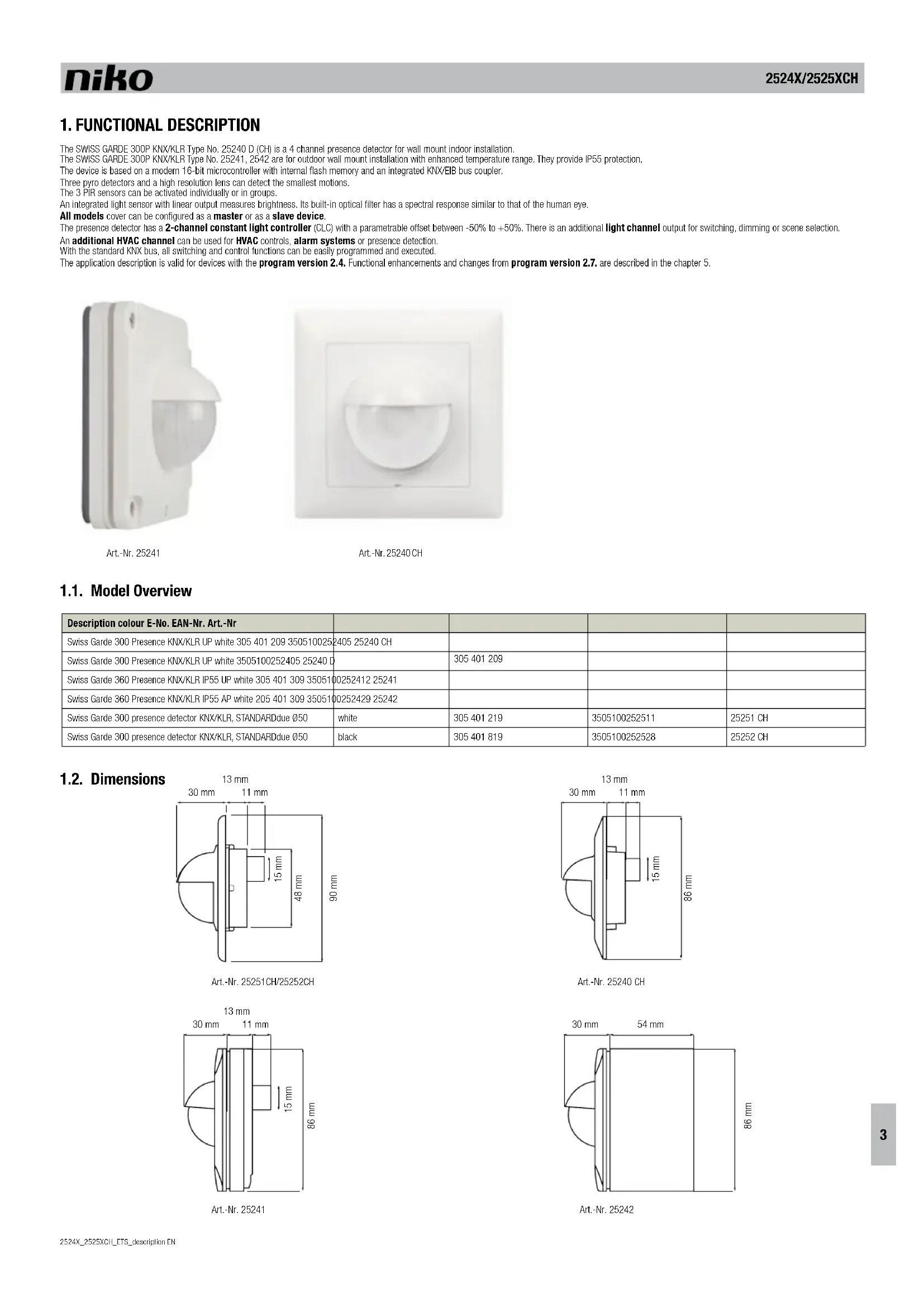
1. FUNCTIONAL DESCRIPTION
The SWISS GARDE 300P KNX/KLR Type No. 25240 D (CH) is a 4 channel presence detector for wall mount indoor installation.
The SWISS GARDE 300P KNX/KLR Type No. 25241, 2542 are for outdoor wall mount installation with enhanced temperature range. They provide IP55 protection.
The device is based on a modern 16-bit microcontroller with internal flash memory and an integrated KNX/EIB bus coupler.
Three pyro detectors and a high resolution lens can detect the smallest motions.
The 3 PIR sensors can be activated individually or in groups.
An integrated light sensor with linear output measures brightness. Its built-in optical filter has a spectral response similar to that of the human eye.
All models cover can be configured as a master or as a slave device.
The presence detector has a 2-channel constant light controller (CLC) with a parametrable offset between -50% to +50%. There is an additional light channel output for switching, dimming or scene selection.
An additional HVAC channel can be used for HVAC controls, alarm systems or presence detection.
With the standard KNX bus, all switching and control functions can be easily programmed and executed.
The application description is valid for devices with the program version 2.4. Functional enhancements and changes from program version 2.7. are described in the chapter 5.
natural_image
White rectangular electronic device with a dome-shaped lens and mounting holes (no visible text or symbols)Art.-Nr. 25241
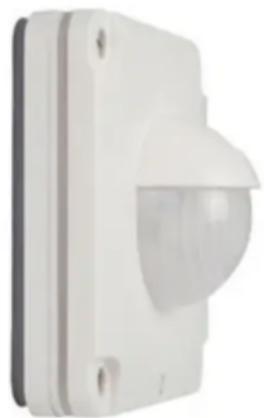
natural_image
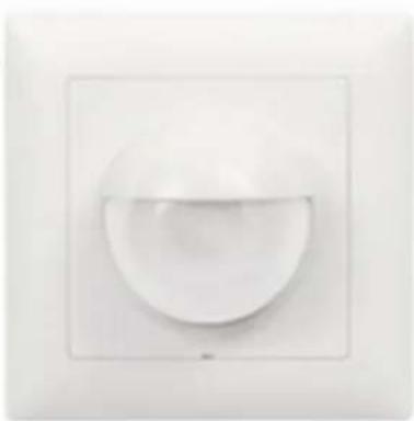
White square wall-mounted circular object with a curved top surface (no text or symbols)Art.-Nr. 25240 CH
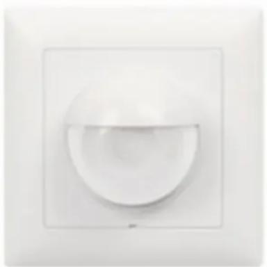
1.1. Model Overview
| Description colour E-No. EAN-Nr. Art.-Nr | ||||
| Swiss Garde 300 Presence KNX/KLR UP white 305 401 209 3505100252405 25240 CH | ||||
| Swiss Garde 300 Presence KNX/KLR UP white 3505100252405 25240 D | 305 401 209 | |||
| Swiss Garde 360 Presence KNX/KLR IP55 UP white 305 401 309 3505100252412 25241 | ||||
| Swiss Garde 360 Presence KNX/KLR IP55 AP white 205 401 309 3505100252429 25242 | ||||
| Swiss Garde 300 presence detector KNX/KLR, STANDARDdue 050 | white | 305 401 219 | 3505100252511 | 25251 CH |
| Swiss Garde 300 presence detector KNX/KLR, STANDARDdue 050 | black | 305 401 819 | 3505100252528 | 25252 CH |
1.2. Dimensions
| Object | Function | link application with | Bit/Byte | |
| 0 | ← | Output - light (preset dimming) light group actuator 1 byte | ||
| 0 | ← | Output - light (switching) light group actuator. 1 bit | ||
| 0 | ← | Output - light (scene) light group actuator 1 bit | ||
| 1 | → | Input external switch / status - light (switching) | KNX switch, touch display, logic 1 bit | |
| 2 | → | Input external motion - light (switching) Output - | light for slave unit (object 0) 1 bit | |
| 3 | → | Input - light (forced control) | External logic module | 2 bit |
| 3 | → | Input - light (lock) | KNX switch, touch display, logic module | 1 bit |
| 4 | ← | Output - HVAC (switching) | Actuators for HVAC devices such as heating, ventilation and air conditioningControl of alarm logic modulesPresence function | 1 bit |
| 5 | → | External switch / status - HVAC (switching) | KNX switch, touch display, logic 1 bit | |
| 6 | → | External motion - HVAC (switching) | Output HVAC for slave unit (output object 4). | 2 byte |
| 7 | → | Input - HVAC (forced control) | External logic module | 2 bit |
| 7 | → | Input - HVAC (lock) | KNX switch, touch display, logic 1 bit | |
| 8 | ← | Threshold switch brightness (switching) | Logic, actuator | 1 bit |
| 9 | ← | Brightness (lux value) | Logic, touch display | 2 byte |
| 10 | ← | AD calibration value | Read out and then set manually for calibration procedure | 2 byte |
| 16 | → | Constant light control, switch on/off | KNX switch, logic | 1 bit |
| 17 | → | Constant light control, dimming relative | 4 bit dimming object from KNX switch for ON/OFF, dimming up and down, touch display | 4 bit |
| 18 | → | Constant light control, preset dimming | Logic module | 1 byte |
| 20 | → | Constant light control, forced control | KNX button, logic | 1 bit |
| 21 | → | Constant light control, scene selection | Logic module | 1 byte |
| 22 | ← | Constant light control, channel 1 - output | Dimming actuator for light group 1 | 1 byte |
| 23 | ← | Constant light control, channel 2 - output | Dimming actuator for light group 2 | 1 byte |
| 24 | → | Light - standby | Switching of standby value sets 1 bit |
* Communication objects program version v2.4
3. PARAMETERS
To set the parameters, the SG360P KNX/KLR RA/EA motion detector should be highlighted in the configuration or operating mode and the command Parameter be selected from the Edit menu item or via the context menu (right mouse click). The Edit parameter... window will open with multiple tabs.
3.1. General
| General | Type of detector | Master Slave |
| Light | Delay time for forced control mode | 9 h |
| Standby value | ||
| HVAC | ||
| Brightness | ||
| Brightness value calibration | ||
| Evaluation of PIR | ||
| Constant light control |
| Type of detector | The function of the detector is set as a master or slave device |
| Delay time for forced control mode | The value "OFF" or a time of 5 min to 9 hrs can be selected in the reset time forced control menu. This parameter defines the time delay for the detector to reset to AUTO mode, after an OFF or ON command has been executed. |
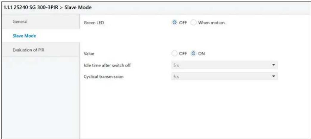
3.1.1. Slave Mode
text_image
1.1.1 25240 SG 300-3PIR > Slave Mode General Green LED OFF When motion Slave Mode Evaluation of PIR Value OFF ON Idle time after switch off 5 s Cyclical transmission 5 s| Slave Mode | The slave mode can be reached in the menu General: click the type of detector as slave and the menu slave mode appears. The delay time of the slave unit is fixed to 30 sec.. |
| LED green For testing purposes, the indication LED for motions can be activated. | |
| Value of object Selectable ON or OFF | |
| Idle time after switch off Can be set from 1 sec to 60 secDefault value is 5 sec | |
| Cyclical transmission We recommend retriggering the Master unit cyclically when operating in the Master/Slave mode.The interval time for cyclical transmission can be set from 1 second to 4 hours.Default value is 30 sec | |
| PIR evaluation | |
| Active sensors | The 3 PIR sensors can be enabled individually or in groups. The numbers 1, 2, and 3 correspond to positions 1, 2, and 3 as shown in the illustration (§3.6). |
| Sensitivity setting The sensitivity can be adjusted from 1 to 10.(1 = min, 10 = max)The default value is 5. | |
3.2. Light - Switch / Dimming / Standby values
| 1.1.1 25240 SG 300-3PIR > Light | ||
| General | Operating mode of the detector | Automatic (no reaction after restart) |
| Light | Green LED | ○ OFF ○ When motion |
| HVAC | Delay time | 1 min |
| Brightness | Brightness below which sensor is active | 500 Lux |
| Brightness value calibration | Brightness switch-off level | OFF |
| Evaluation of PIR | Forced control object or disabled object | ○ Force control object ○ Disable object |
| Constant light control | If disabled object = 0 | Automatic |
| If disabled object = 1 | Forced control OFF | |
| Object type for output - light | Switching | |
| Object value for ON | ○ OFF ○ ON | |
| Object value for OFF | ○ OFF ○ ON | |
| Transmission condition for switching object | ON and OFF | |
| Transmission condition for external switch | ON and OFF | |
| Idle time after switch off | 1 s | |
| Cyclical transmission | OFF | |
| Operating mode of the detector Sets the operating mode to fully or semi-automatic. | |
| Green LED This LED may flash once after each motion detection or remain off | |
| Delay time The delay time for the light channel can be set from 1 sec to 4 hrs | |
| Brightness below which sensor is active Set lighting value from 10 Lux to 2000 Lux and always.Important: If the light channel always remain active ( even with values > 2000 lux,the parameter must be to always. | |
| Brightness above which lighting is turned off | Brightness threshold (lux) for immediate switch-off, even if delay time has not yet elapsed. Default value is OFF. |
| Forced control object or disabled object | This will set object 3. See description of object 3: force control mode – lock mode (§3.6) |
| If locked object = 0 Selects an action to be executed after reception of a 0 command | |
| If locked object = 1 Selects an action to be executed after reception of a 1 command | |
| Object type for output - light | This will define object 0. The following options are available: switching, dim completely, scene selection |
| Object value for ON when object type is:light = switchinglight = dimminglight = scene | Select ON or OFF (ON is default value)Select preset dim value from 0% to 100%Select scenes from 1...32 |
| Object value for OFF when object type:light = switchinglight = dimminglight = scene | Select ON or OFF (OFF is default value)Select preset dim value from 0% to 100%Select scenes from 1...32 |
| Transmission conditions for switchingobject | Transmission filter for output object 0: Output - Light - SwitchingSelection: ON and OFF; neither ON nor OFF; only ON; only OFF |
| Transmission conditions for external switch | Selection: ON and OFF; neither ON nor OFF; ON only; OFF only |
| Idle time after switch off Can be set from 1 sec to 60 secsApplications:Prevention off bus traffic excessPrevention of erroneous lighting restart if:• light bulbs are cooling down• room is deserted after switching off with a KNX switch. | |
| Cyclical transmission If the light channel is in switching mode, it is possible to cyclically transmit the "ON" mode.The interval time for cyclical transmission can be set from 1 second to 4 hours. | |
3.2.1. Light - Preset Dimming
| 1.1.1 25240 SG 300-3PIR > Light | ||
| General | Operating mode of the detector | Automatic (no reaction after restart) |
| Light | Green LED | OFF When motion |
| Standby value | Delay time | 1 min |
| HVAC | Brightness below which sensor is active | 500 Lux |
| Brightness switch-off level | OFF | |
| Brightness | Forced control object or disabled object | Force control object Disable object |
| Brightness value calibration | If disabled object = 0 | Automatic |
| If disabled object = 1 | Forced control OFF | |
| Evaluation of PIR | Object type for output - light | Dim completely |
| Constant light control | Object value for ON | 100% |
| Object value for OFF | 0% | |
| Transmission condition for switching object | ON and OFF | |
| Transmission condition for external switch | ON and OFF | |
| Idle time after switch off | 1 s | |
Object type for output-light Preset dimming
This setting enables the standby light function. The Standby value option appears in the Light menu.
3.2.2. Light - Standby parameters
| 1.1.1 25240 SG 300-3PIR > Standby value | ||
| General | Standby values | Active Inactive |
| Light | Standby time 1 | 1 h |
| Standby value | Standby value 1 | 80% |
| Standby time 2 | 50 min | |
| HVAC | Standby value 2 | 75% |
| Brightness | ||
| Brightness value calibration | ||
| Evaluation of PIR | ||
| Constant light control | ||
| Standby values Toggles the orientation light function between active and inactive |
| Standby time 1 Set orientation light 1 duration time (seconds, minutes, hours). |
| Standby value 1 Set light intensity in % (0...100%) |
| Standby time 2 Set orientation light 2 duration time (seconds, minutes, hours). |
| Standby value 2 Set light intensity in % (0...100%) |
Standby light
If the light channel is set to preset dimming, a new menu will appear to enable the standby functionality.
There are 2 parameters for both the duration time and the light intensity (%) of the standby operation.
After the regular duration time has elapsed the standby light will turn on. With object 24 → the user will then be able to select one of two presetable parameter pairs. If the object value is 0 or there was no command received yet, value pair 1 is enabled. A 1 command value will trigger pair 2.
After standby has elapsed, an OFF command will be sent on the light channel.
The motion detector will return to regular mode and standby mode will be reset
Lock commands and forced control commands will always reset standby mode immediately.
3.3. HVAC
| 1.1 25240 SG 300-3PIR > HVAC | ||
| General | Operating mode of the detector | Fully automatic Semi automatic |
| Light | LED | OFF When motion |
| Standby value | Delay time | 5 min |
| Number of monitoring time intervals | 1 | |
| HVAC | Forced control object or disabled object | Force control object Disable object |
| Brightness | If disabled object = 0 | Automatic |
| Brightness value calibration | If disabled object = 1 | Forced control OFF |
| Evaluation of PIR | Length of the monitoring time interval (s) | 1 |
| Constant light control | Object type for output - HVAC | Switching |
| Object value for ON | OFF ON | |
| Object value for OFF | OFF ON | |
| Transmission condition for switching object | ON and OFF | |
| Transmission condition for external switch | ON and OFF | |
| Idle time after switch off | 1 s | |
| All parameters are identical to those of the light channel with the exception of: | |
| Number of monitoring time windows The number of monitoring time intervals can be set from 1 to 32. | |
| Duration of monitoring time window Adjustable from 1 s to 30,000 s (8.33h) | |
| Note! The correct setting for fastest response of the HVAC channel is:Number of monitoring time windows: 1Duration of monitoring time window: 1 second | |
| Presence functionwith HVAC channel | The above parameters should be used for the presence function (the presence signal is independent from the ambient lighting brightness!) |
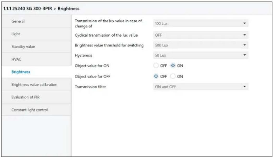
3.4. Brightness / threshold switch / Value calibration
| 1.1.1 25240 SG 300-3PIR > Brightness | ||
| General | Transmission of the lux value in case of change of | 100 Lux |
| Light | Cyclical transmission of the lux value | OFF |
| Standby value | Brightness value threshold for switching | 500 Lux |
| HVAC | Hysteresis | 50 Lux |
| Brightness | Object value for ON | OFF ON |
| Object value for OFF | OFF ON | |
| Transmission filter | ON and OFF | |
| Brightness value calibration | ||
| Evaluation of PIR | ||
| Constant light control | ||
| The parameters for object 8 ← (Brightness threshold switch, 1 bit) and object 9 ← (Brightness value, 2 bytes) can be set in the Brightness / Threshold menu. | |
| Transmission of the lux value in case of change of | This parameter allows the lux value + change to be sent via object 9 (brightness value) if the set threshold is exceeded. Values from 10 lux up to 1800 lux and "OFF" can be set. The set value of change refers to the set threshold. |
| Cyclical transmission of the light value Values | from 5 seconds to 30 minutes and "OFF" can be set. |
| Lux value of the threshold for switching Can | be set from 10 lux to 2000 lux |
| Hysteresis Can be set from 5 lux to 200 lux | |
| Object value for ON Selection: "ON" or "OFF" | |
| Object value for OFF Selection: "OFF" or "ON" | |
| Transmission filter | Selections: "ON and OFF"; "neither ON nor OFF"; "ON only"; "OFF only" |
3.5. Brightness value calibration
| 1.1.1 25240 SG 300-3PIR > Brightness value calibration | ||
| General | Adjustment brightness sensor | Custom calibration |
| Light | ||
| Standby value | AD calibration value | 0 |
| HVAC | Lux value | 0 |
| Brightness | ||
| Brightness value calibration | ||
| Evaluation of PIR | ||
| Constant light control | ||
| Calibration "NO": Factory calibration is enabled (default value)Reset to factory calibration: This is possible at any time with the setting "NO" and thereafter the reprogramming of the detector."YES": This option opens the following two additional windows: |
| AD calibration value Read AD calibration value (at ← object 10) in the ETS and enter it in the window.Attention: use type 7.001 unsigned 2 byte counter in the read/send value menu! The AD value read-out then appears in the Value received menu (e.g. 739 pulses). |
| Lux value Measure reference brightness with lux meter and enter corresponding value. |
3.6. PIR evaluation
| 1.1.1 25240 SG 300-3PIR > Evaluation of PIR | ||
| General | Active sensors | 123 |
| Light | Sensitivity settings 1 = min, 10 = max | 5 |
| Standby value | ||
| HVAC | ||
| Brightness | ||
| Brightness value calibration | ||
| Evaluation of PIR | ||
| Constant light control | ||
| Active sensors | The 3 PIR sensors can be enabled individually or in groups. The numbers 1, 2, and 3 correspond to positions 1, 2, and 3 as shown in the illustration below. |
| Sensitivity setting The sensitivity can be adjusted from 1 to 10. (1 = min, 10 = max)The default value is 5. | |
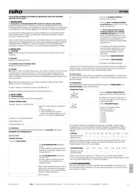
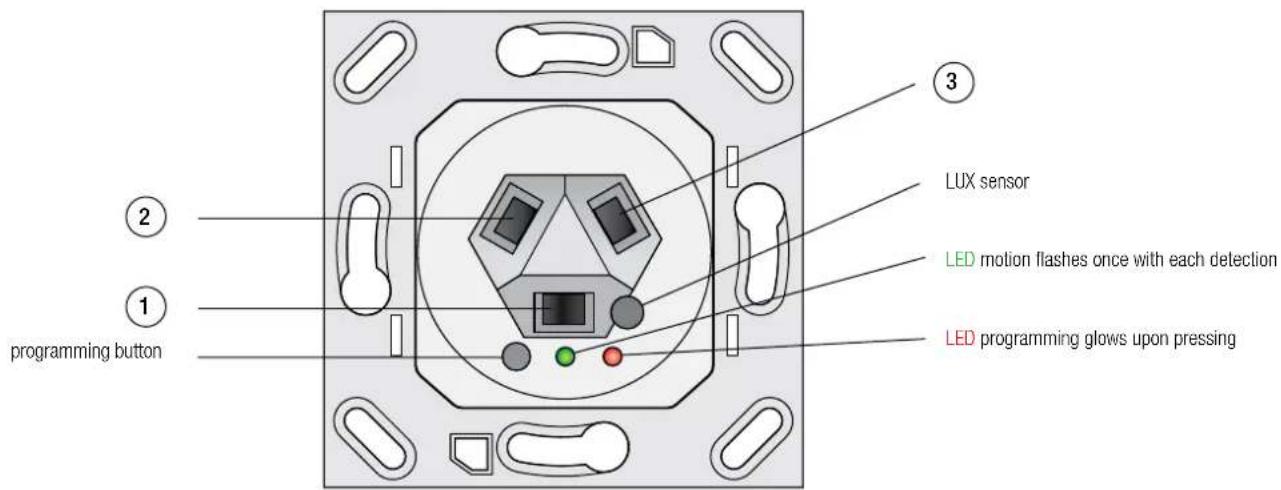
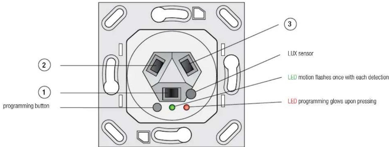
Numbering of the PIR sensors
text_image
programming button 1 2 3 LUX sensor LED motion flashes once with each detection LED programming glows upon pressingThe PIR sensors 1, 2 and 3 can be enabled individually or in groups of two.
The 3 positions of the pyro detectors are visible in the above illustration.
3.7. Constant light control
| 1.1 25240 SG 300-3PIR > Constant light control | ||
| General | Constant light controller | Switch-off Switch-on |
| Light | Channel 2 for constant light control | Active Inactive |
| Standby value | Preset setpoint | 300 ix |
| Transmit difference | 3% | |
| HVAC | Switch constant light control with | Motion detector light |
| Brightness | Time interval for cyclic transmission | No cyclical transmission |
| Brightness value calibration | ||
| Evaluation of PIR | Switch on brightness value | 70% |
| Time after switch-on until constant light control starts | 5 s | |
| Constant light control | ||
| Forced control during switch-on | No reaction | |
| Forced control during switch-off | No reaction | |
| Time for relative dimming | 5 s | |
| Take over setpoint after | 5 s | |
| Changed setpoint to flash memory | disabled enabled | |
| Keep changed setpoint | No Yes | |
| Scene | Switch-off Switch-on | |
| Dead zone | 4 | |
3.7.1. Constant light scenes
| General | Preset setpoint | 300 lx |
| Light | Transmit difference | 3% |
| Standby value | Switch constant light control with | Motion detector light |
| HVAC | Time interval for cyclic transmission | No cyclical transmission |
| Brightness | Switch on brightness value | 70% |
| Brightness value calibration | Time after switch-on until constant light control starts | 5 s |
| Evaluation of PIR | ||
| Constant light control | Forced control during switch-on | No reaction |
| Forced control during switch-off | No reaction | |
| Time for relative dimming | 5 s | |
| Take over setpoint after | 5 s | |
| Changed setpoint to flash memory | disabled enabled | |
| Keep changed setpoint | No Yes | |
| Scene | Switch-off Switch-on | |
| Scene 1 | 500 lx | |
| Scene 2 | 500 lx | |
| Scene 3 | 500 lx | |
| Scene 4 | 500 lx | |
| Scene 5 | 500 lx | |
| Scene 6 | 500 lx | |
| Scene 7 | 500 lx | |
| Scene 8 | 500 lx |
3.8. Constant light parameters
| Constant light controller This parameter enables or disables the constant light controller. | |
| Channel 2 for constant light control Channel 2 can be enabled for constant light controlActive/inactive Via the output object 23 a configurable value with a fixed offset can be transmitted | |
| Preset setpoint | The preset setpoint in lux for constant light control can be preset in the ETS. It can also be changed via objects 17 and 18 (constant light - dimming relative and constant light - dim completely). |
| Transmit difference | This parameter (from 1% to 100%) defines the tolerance window to be exceeded in order to send a new brightness control value. |
| Switching constant light control with | Switching constant light control ON/OFF can be done using three different sources:By → object 16, presence detection on the light channel or presence detection on the HVAC channel. |
| Time interval for cyclical transmission | Defines the cycle time interval with which the last brightness value is repeated, even if it has not exceeded the tolerance window.Cyclical transmission can also be disabled. |
| Switch on brightness value The switch on value for the lighting can be set from 1% to 100%. | |
| Switch on timeout This parameter defines the initial time delay before constant light control is started. | |
| Offset for channel 2 * The offset range for channel 2 can be set from -50%, 0% to +50%. | |
| Force control during switch-on | This parameter allows the constant light controller function to be set to: no reaction, minimum brightness, maximum brightness |
| Force control during switch-off | This parameter allows the constant light controller function to be set to: no reaction, minimum brightness, maximum brightness |
| Time for relative dimming | This parameter allows the relative dimming time to be set. This will influence the dimming soft control. |
| Take over set point after | This parameter allows setting the time delay after which a new setpoint will be recognized and stored in the RAM memory. |
| Changed setpoint to flash memory | This parameter allows a new set point to be written to the flash memory. |
| Keep changed set point | Here at Yes the changed value is stored in the RAM.Attention: now corresponds to the new nominal value of the last new dimmed brightness! |
| Scene | Various lux values can be set as light scenes (light moods). These can be enabled through object 21 as well. |
| Dead zone | The dead zone is an area within which the actual light value can change without generating new control commands. The default value for the dead zone is 2.The lux value tolerance of the dead zone can be extracted from the table below.Example:Dead zone value = 2Brightness = 500 luxThe resulting tolerance is: +/- 24 luxThis means that the actual value can change from 476 lux to 524 lux without sending new control inputs to the actuator. |
In addition to the previous constant light control channel 1 (Object 22 ) there is a second constant light control channel 2 (Object 23 ). The control signal of channel 1 ± offset value is sent to the dimming actuator for light channel 2. Internally, the control range has been extended to ± 150% in order to maintain a reasonable control range at the limits.
That means: Offset at -50%, darkness: FF (=100%) is sent to both objects. Internally, object 1 is at 150% and object 2 at 100%. If the ambient brightness now increases, object 1 remains at 100% (150% - x) and object 2 is regulated downwards (150% - 50% - x). If the regulation now drops below 100%, object 1 will also be visibly smaller on the bus, e.g. 73%, object 2 23%. Object 1 is then regulated down to 0 and object 2 is set to the minimum value of 50%. The values for transmission difference and cyclical transmission are taken from the once off available parameters.
3.9. Dead zone/Brightness correlation
Brightness in lux, +/- lux tolerance (dead band)
| Dead zone | |||||||||||
| 1 2 3 4 5 | 6 7 8 9 10 | ||||||||||
| Brightness 100 | 2 5 7 10 12 15 17 | 20 23 26 | |||||||||
| 200 5 9 14 | 19 24 30 35 40 | 46 52 | |||||||||
| 300 7 14 21 | 29 37 44 52 61 | 69 78 | |||||||||
| 400 9 19 29 | 39 49 59 70 81 | 92 104 | |||||||||
| 500 12 24 | 36 48 61 74 87 101 | 115 129 | |||||||||
| 600 14 28 | 43 58 73 89 105 | 121 138 155 | |||||||||
| 700 16 33 | 50 68 85 104 122 | 142 161 181 | |||||||||
| 800 19 38 | 57 77 98 119 140 | 162 184 207 | |||||||||
| 900 21 42 | 64 87 110 133 157 | 182 207 233 | |||||||||
| 1000 23 47 | 72 96 122 148 | 175 202 230 259 | |||||||||
| 1100 26 52 | 79 106 134 163 | 192 222 253 285 | |||||||||
| 1200 28 57 | 86 116 146 178 | 210 243 276 311 | |||||||||
| 1300 30 61 | 93 125 159 193 | 227 263 299 337 | |||||||||
| 1400 33 66 | 100 135 171 207 | 245 283 322 362 | |||||||||
| 1500 35 71 | 107 145 183 222 | 262 303 345 388 | |||||||||
| 1600 37 75 | 114 154 195 237 | 280 324 368 414 | |||||||||
| 1700 40 80 | 122 164 207 252 | 297 344 391 440 | |||||||||
| 1800 42 85 | 129 174 220 267 | 315 364 414 466 | |||||||||
| 1900 44 90 | 136 183 232 281 | 332 384 438 492 | |||||||||
| 2000 47 94 | 143 193 244 296 | 350 405 461 518 | |||||||||
4. FUNCTIONAL BLOCKS
The functionality of the presence detector can be split up into the following blocks:
- Motion detection
- Brightness measuring
• Light control channel Switching
• Light control channel preset dimming with optional standby light function
• HVAC control channel (with presence function)
• Lighting dependent threshold switch
• 2 channel constant light control
The motion detector and the brightness sensor (lux) each work independently on the light channel and the HVAC channel.
The constant light controller receives the actual brightness value from the Lux sensor. The controller can
be switched on/off by a command via → object 16 or triggered by motion detection on the light or HVAC channel.
After switching or recovery of the KNX bus voltage, the presence detector usually generates a switch-on procedure.
4.1. Light control channel
The light control channel has two operating modes that can be selected via the detector operating mode parameters.
The possible settings are:
- fully-automatic
- semi-automatic
The differences between the fully-automatic and semi-automatic modes are:
• fully-automatic mode has three operating conditions: ready, active and passive
• semi-automatic mode has two operating conditions: ready and active
• semi-automatic mode does not switch the light on after motion has been detected.
Lighting can only be switched on manually by an external KNX switch.
4.1.1. OBJECT 0 OUTPUT - LIGHT - SWITCH
← Output 1 bit
After each detected motion this output sends an "ON" command and starts the delay timer
The delay time can be set with parameter delay time from 1 second to 4 hours.
At the end of the programmed time interval an "OFF" command is sent to the output (object 0).
4.1.2. OBJECT 0 OUTPUT - LIGHT - COMPLETE DIMMING
← Output 1 byte
This mode sends preselected dim values (0% to 100%) to the output for objective value for ON and for objective value for OFF respectively.
4.1.3. OBJECT O OUTPUT - LIGHT - SCENE
← Output 1 byte
For the Objective value for ON or Objective value for OFF one of 32 scenes can be selected respectively.
4.1.4. OBJECT 1 EXTERNAL SWITCHING / STATUS - LIGHT - SWITCH
→ Input 1 Bit
Input object 1 external switch / status can be used in two different ways:
- As an input for an external push button that directly switches on the light
- As an input for monitoring the status or the input of an actuator
In both cases, a received telegram „ON“ sets the detector to the ON state and an „OFF“ telegram to the ready state.
Whether commands for ON or OFF will be sent during the transitions depends on the parameter sending conditions for external push button.
After having received an ON command, the follow up timer starts as if a motion had been detected.
Lighting is subsequently switched off again.
After having received an OFF command the detector remains in its passive status during which it will not detect any motion. After having passed the idle time after switch off, the detector is ready again.
The idle time after switch off can be programmed in the light menu.
4.1.5. OBJECT 2 EXTERNAL MOVEMENT - LIGHT - SWITCH
→ Input 1 Bit
Additional detectors (slaves) can be connected through Object 2 "external movement - light - switching".
The received signal from external presence detectors is processed the same as if from its own detector and works in parallel.
Object 2 is used to set up a Master-Slave configuration as follows:
Slave devices: Connect all outputs of the slave devices (←object 0) to the input external movement-light-switching (-object 2) of the master device.
4.1.6. OBJECT 3 INPUT - LIGHT - FORCED CONTROL / LOCK
→ Input 2 Bit
The meaning of this object is defined by the Light - focused control object or disabling object parameter.
Forced control object:
Object 3 when used as forced control object has 3 values which can be received by a 2 bit command:
- Forced control object ON (control = 1, value = 1)
An ON command is sent unconditionally to the output – light (object 0).
The follow up timer is disabled and the timer release time starts.
If after having terminated the release time and no further command is sent to the forced control object, normal operation is resumed.
- Forced control object OFF (control = 1, value = 0)
An OFF command is sent unconditionally to the output - light (object 0).
The delay timer is disabled and the timer release time starts.
If after having terminated the release time and no further command is sent to the forced control object, normal operation is resumed.
- Forced control object auto (control = 0, value = 0)
Normal operation is resumed immediately.
Locked object:
Object 3 when used as locked object has 2 values which can be received by a 1 bit command 0 and 1:
The response to a switch command on this object is controlled by two more parameters:
Light → if locked object = 0, and Light → if locked object = 1,
Both parameters can specify one of the following commands:
- forced control ON
- forced control OFF
- automatic
- lock (actual state)
- do nothing
Note: Incorrect settings of parameters such as: locked object, lock at 0 and no action at 1 and release time restraint OFF can completely inactivate the correct function of the presence detector.
4.2. HVAC channel
← Output 1 bit
The HVAC channel has the same objects and the same operating modes as the light channel. It works the same way as the light channel as well.
The motion detection function, however, has been expanded and substituted by a "longer presence detection". This is done by setting several equally long monitoring time windows. At least one motion detection must occur during each time slot.
The parameters are:
• number of monitoring time windows
• length of monitoring time window (s)
Presence function
The HVAC output can be used as a presence detection. To activate this, the number of observation time windows must be set to 1 and the length of the observation time window set to 1 second. The presence signal is independent of the ambient light level.
4.2.1. OBJECT 4 OUTPUT - HVAC - SWITCH
← Output 1 bit
Object 4 "Output - HVAC - Switch" is similar to object 0 "Output - light - switch" but has additional functions (see HVAC parameters, page 10).
4.2.2. OBJECT 5 EXTERNAL SWITCHING / STATUS - HVAC
→ Input 1 Bit
Object 5 "External switching / status - HVAC" is identical to object 1 "External switching / status - light".
4.2.3. OBJECT 6 EXTERNAL MOVEMENT - HVAC
→ Input 1 Bit
Object 6 "External movement - HVAC - switch" is identical to object 2 "External movement - light - switch".
4.2.4. OBJECT 7 INPUT - HVAC - FORCED CONTROL
→ Input 2 Bit
Object 7 "Input - HVAC - forced control" is identical to object 3 "Input - light - forced control".
4.2.5. OBJECT 7 INPUT - HVAC - DISABLE
→ Input 1 Bit
Object 7 "Input - HVAC - disable" is identical to object 3 "Input - light - disable".
4.3. BRIGHTNESS THRESHOLD SWITCH
text_image
1.1.1 25240 SG 300-3PIR > Brightness General Light Standby value HVAC Brightness Brightness value calibration Evaluation of PIR Constant light control Transmission of the lux value in case of change of Cyclical transmission of the lux value Brightness value threshold for switching Hysteresis Object value for ON Object value for OFF Transmission filter 100 Lux OFF 500 Lux 50 Lux OFF ON OFF ON ON and OFFThis block has two output objects: Threshold switch and brightness value
4.3.1. OBJECT 8 THRESHOLD SWITCH BRIGHTNESS - SWITCHING
← Output 1 bit
Output object 8 sends an "ON" if the measured brightness is greater than the Value for switching the threshold value switch parameter. If the measured brightness drops below the Switch-on threshold value – (minus) the Hysteresis parameter, an "OFF" is transmitted.
4.3.2. OBJECT 9 BRIGHTNESS VALUE
← Output 2 bytes
Output object 9 sends the current measured brightness value in lux. The transmission is triggered by changes that are greater than the parameter Transmission of the light value in case of a change of or cyclically with the time stipulated for Cyclical transmission of the light value.
If the cycle time is set to "OFF" there will be no cyclical transmission.
4.4. AD calibration value
← Output 2 bytes
Object 10 is not transmitted autonomously. It can only be read. Its unsigned 16 bit value represents the momentary value of the AD converter for the brightness measurement.
The brightness measurement can be calibrated as follows:
- Measure the incident light - on a desktop for example - with an external lux meter. This represents the reference lux value.
- Read out the AD calibration value (communication object 10) in the ETS.
Note: In the menu Read/send value, use type 7.001 unsigned 2 byte counter!
The AD value read then appears in the Value received menu as 739 pulses, for example. - With full access, enter the two values Lux value and AD calibration value as parameters.
1.1.1 25240 SG 300-3PIR > Brightness value calibration
General
Light
Standby value
HVAC
Brightness
Brightness value calibration
Evaluation of PIR
Constant light control
Adjustment brightness sensor
AD calibration value
Lux value
Custom calibration
| 0 | |
| 0 |
4.5. OBJECTS FOR CONSTANT LIGHT CONTROL
4.5.1. OBJECT 16 CONSTANT LIGHT - SWITCH ON/OFF
→ Input 1 bit
This input allows the constant light controller to be switched ON and OFF (Object).
Alternatively the constant light controller can be activated by motion detection on the light or the HVAC channel.
4.5.2. OBJECT 17 CONSTANT LIGHT - RELATIVE DIMMING
→ Input 4 bit
Using this object, the current value is changed with relative dimming steps of 1%.
Using a KNX push button, light can be dimmed and set to a new brightness level.
The new light value can then be displayed in Lux on a KNX touch panel through object 9: brightness value.
Important: In the menu constant light → take over set point after you can define the period during which the controller will remain switched off. After this interval, the new value is written to the RAM (not to the flash memory)!
Note: This new target value remains stored in RAM as long as there are people present in the scanned area. After switching the light channel off and back on again, the set point stored in ETS is adopted once again. If the newly changed set point are definitely taken over, set the parameter Keep changed set point to YES (see also section 3.8 Constant light parameter page 18)
4.5.3. OBJECT 18 CONSTANT LIGHT - PRESET DIMMING
→ Input 1 Byte
With this object the user can define a new dim set point in % over the bus.
4.5.4. OBJECT 20 CONSTANT LIGHT - FORCE CONTROL
→ Input 1 bit
In accordance to the parameters force output at ON and force output at OFF, various options can be selected: no reaction, minimum brightness, maximum brightness
4.5.5. OBJECT 21 CONSTANT LIGHT - SCENE
→ Input 1 byte
Scene selection input. 8 adjustable scenes can be selected via ETS.
This object has no switch function but only changes the brightness setpoint values.
4.5.6. OBJECT 22 CONSTANT LIGHT - OUTPUT CHANNEL 1
← Output 1 byte
This is the constant light control signal (% brightness) for the dimming actuator of lighting 1
4.5.7. OBJECT 23 CONSTANT LIGHT - OUTPUT CHANNEL 2
← OUTPUT 1 byte
This is the constant light control signal for the dimming actuator of lighting 2.
The lux value is equal to channel 1 +/- offset.
5. PROGRAMMVERSION 2.7
With the program version 2.7, the function possibilities of the presence detector - series Swiss Guard 360P KNX / KLR RA / EA expanded and existing features of program version 2.4, have been supplemented respectively adapted.
The standard values (default values) of the parameters compared to the settings in version 2.4 are partially modified. These settings allow a simple and safe functionally check (initial start-up) of the presence detector.
Older devices of software version 2.4 can also be programmed with the program version 2.7 (backward compatibility). However, supplemented functions and the additional communication objects are not all supported.
5.1. Overview of the changes:
- Forced control Slave-Mode see 5.2.0
- Parameter changes via communication objects see 5.2.1
- Dimming function with constant light control (clc) see 5.2.2
• Power on characteristics see 5.3.1
• Automatic lighting OFF threshold see 5.3.2 - Delay time in semi-automatic mode see 5.3.3
• Standby-function see 5.3.4
• Light sensor adaption see 5.3.5
5.2. Communication objects

input objects output objects
| Object | Function | link application with | Bit/Byte | |
| 0 | ← | Output - light (preset dimming) | light group actuator | 1 byte |
| 0 | ← | Output - light (switching) light group actuator. | 1 bit | |
| 0 | ← | Output - light (scene) | light group actuator | 1 bit |
| 1 | → | Input external switch / status - light (switching) | KNX switch, touch display, logic | 1 bit |
| 2 | → | Input external motion - light (switching) | Output - light for slave unit (object 0) | 1 bit |
| 3 | → | Input - light (forced control) | External logic module | 2 bit |
| 3 | → | Input - light (lock) | KNX switch, touch display, logic module | 1 bit |
| 4 | ← | Output - HVAC (switching) | Actuators for HVAC devices such as heating, ventilation and air conditioningControl of alarm logic modulesPresence function | 1 bit |
| 5 | → | External switch / status - HVAC (switching) | KNX switch, touch display, logic | 1 bit |
| 6 | → | External motion - HVAC (switching) | Output HVAC for slave unit (output object 4). | 2 byte |
| 7 | → | Input - HVAC (forced control) | External logic module | 2 bit |
| 7 | → | Input - HVAC (lock) | KNX switch, touch display, logic | 1 bit |
| 8 | ← | Threshold switch brightness (switching) | Logic, actuator | 1 bit |
| 9 | ← | Brightness (lux value) | Logic, touch display | 2 byte |
| 10 | ← | AD calibration value | Read out and then set manually for calibration procedure | 2 byte |
| 16 | → | Constant light control, switch on/off | KNX switch, logic | 1 bit |
| 17 | → | Constant light control, dimming relative | 4 bit dimming object from KNX switch for ON/OFF, dimming up and down, touch display | 4 bit |
| 18 | → | Constant light control, preset dimming Logic module | 1 byte | |
| 20 | → | Constant light control, forced control | KNX button, logic | 1 bit |
| 21 | → | Constant light control, scene selection Logic module | 1 byte | |
| 22 | ← | Constant light control, channel 1 - output | Dimming actuator for light group 1 | 1 byte |
| 23 | ← | Constant light control, channel 2 - output | Dimming actuator for light group 2 | 1 byte |
| 24 | → | Light - standby | Switching of standby value sets | 1 bit |
5.2.1. COMMUNICATION OBJECTS with SLAVE- Mode
| Object | Function | link application with | Bit/Byte | |
| 0 | ← | Output (switching) Master presence -detector | 1 bit | |
| 3 | → | Input (forced control) | KNX switch, touch display, logic module | 1 bit |
Object forced control:
The object 3 as a forced control object knows 2 values (1 bit command) which can be received :
If object forced control = 1: output (Obj.0) remains locked when motion is detected, no telegrams are sent
If object forced control = 0: output (Obj.0) → AUTO (normal operation)
5.2.2. OBJECTS FOR DYNAMIC PARAMETER CHANGES

Input 2 byte
Output 2 byte
Via object 11 (delay time) and via object 12 (brightness below which sensor is active) may be changed or read the related parameter- values directly without to re-programming the presence- detector. This mode allows via external devices (BMS, touch screen, logic) to influence the functioning of the presence- detector directly.
For example, dependent on user needs, the light-ON switching characteristic / delay time can be dynamically adapted during certain day times to optimize the application
Changed values via object remain stored temporarily. After bus voltage interruption / return, after a reset or after a re-programming, the originally parameterized values are active again.
5.2.3. Object 14 CONSTANT LIGHT CONTROL - FORCED DIMMING

Input 4 bit
If the constant light control of the Presence detector is activated by a presence detection or by an external "ON"- command (obj1), dimming values (brighter or darker) transmitted to object 14 interrupt the function Constant-light-control immediately and remains inactive during motion detection and or the delay-time.
At that moment, the constant-light-control output-value (Obj 22) can with relative dimming (brighter / darker) by a KNX push button - to be changed.
After the delay-time or after an external "OFF" switching command, the constant-light-control is active again and operates (when motion-detection) with the stored parameter-values.
5.3. Parameters
5.3.1. Operating mode during power-on
After power -on/ bus voltage return or bus voltage interruption, the presence-detector is for the first 60sec inactive. During this stabilization-period of the electronic device, the detector doesn't sends any telegrams too.
Dependent on the application, in the operating mode "Automatic", the light output (obj1/obj22) can be activated during the start-up phase.
In this mode, two options with "75s light on after restart" or "no reaction after restart" can be selected.
| 1.1.1 25240 SG 300-3PIR > Light | ||
| General | Operating mode of the detector | Automatic (no reaction after restart) |
| Light | Green LED | Automatic (no reaction after restart)Semi automatic |
| Standby value | Delay time | Automatic (75 s light on after restart) |
| HVAC | Brightness below which sensor is active | 500 Lux |
| Brightness switch-off level | OFF | |
| Brightness | Forced control object or disabled object | Force control objectDisable object |
| Brightness value calibration | If disabled object = 0 | Automatic |
| If disabled object = 1 | Forced control OFF | |
| Evaluation of PIR | Object type for output - light | Dim completely |
| Object value for ON | 100% | |
| Object value for OFF | 0% | |
| Transmission condition for switching object | ON and OFF | |
| Transmission condition for external switch | ON and OFF | |
| Idle time after switch off | 1 s | |
5.3.2. Automatic adaptation of the "light-off" threshold
With the setting "Automatic" in the parameter Brightness above which lighting is turned off, the detector calculates automatically the light-off threshold with the following rule: If the effective brightness with switched light-channel (after 1min.) is greater than the parameterized value, Brightness below which sensor is active", the light-off threshold is 10% increased above this value plus 200LUX.
If the effective brightness with switched light-channel (after 1min.) is below than the parameterized value „Brightness below which sensor is active“, the light-off threshold is 10% increased above the actual brightness-value (obj9) plus 200LUX.
| 1.1 25240 SG 300-3PIR > Light | ||
| General | Operating mode of the detector | Automatic (no reaction after restart) |
| Light | Green LED | OFF When motion |
| Standby value | Delay time | 1 min |
| HVAC | Brightness below which sensor is active | 500 Lux |
| Brightness | Brightness switch-off level | OFF |
| Brightness | Forced control object or disabled object | OFF |
| Brightness value calibration | If disabled object = 0 | 10 Lux |
| 20 Lux | ||
| Evaluation of PIR | If disabled object = 1 | 40 Lux |
| Constant light control | Object type for output - light | 60 Lux |
| 80 Lux | ||
| Object value for ON | 100 Lux | |
| 120 Lux | ||
| Object value for OFF | 140 Lux | |
| Transmission condition for switching object | 160 Lux | |
| 180 Lux | ||
| Transmission condition for external switch | 200 Lux | |
| 220 Lux | ||
| Idle time after switch off | 240 Lux | |
| 260 Lux | ||
| 280 Lux | ||
| 300 Lux | ||
The light-off threshold is recalculated after each expired delay-time and a renewed motion-detection or an "ON" switching-command.
If the parameter Brightness switch-off level is selected with a fixed value, this value needs to be higher or the same as the parameter Brightness below sensor is active.
5.3.3. Delay-time, mode semi-automatic
If the brightness is increasing during the delay-time and passes over the threshold "Brightness switch off level", the light-channel (obj0/obj22) is switching off but the delay-time is continuing either. If the brightness reduces below the value "Brightness below sensor is active", the light channel is switching "ON" again, till the delay-time is expired.
5.3.4. Standby-functionality
When the light-channel is used as "dim completely", a standby-light can be activated optionally.
Two pairs of values are available and can select with obj24.
The delay-time for the Standby-functionality can also parameterized as "Unlimited" too. Emergency-light
with permanent minimum brightness.
If the brightness during standby increase over "Brightness switch off level", the light-channel (obj0) is switching off.
If the brightness reduces below the value "Brightness below sensor is active", the light channel is switching "ON" with the standby-settings again till the delay-time (standby) is expired.
| General | Standby values | Active Inactive |
| Light | Standby time 1 | 1 h |
| Standby value | Standby value 1 | 80% |
| Standby time 2 | 50 min | |
| HVAC | Standby value 2 | OFF 1 min 2 min 5 min 10 min 20 min 30 min 40 min 50 min |
| Brightness | ||
| Brightness value calibration | ||
| Evaluation of PIR | ||
| Constant light control | ||
| 1 h 2 h 4 h 8 h Unlimited |
5.3.5. Adjustment brightness sensor
| Brightness value calibration | 1.1.1 25240 SG 300-3PIR > Brightness value calibration | ||
| General | Adjustment brightness sensor | Custom calibration | |
| Light | AD calibration value | Factory calibration | |
| Standby value | Lux value | Custom calibration | |
| HVAC | Keep internal value | ||
| Brightness | U | ||
| Brightness value calibration | |||
| Evaluation of PIR | |||
| Constant light control | |||
| Factory calibration This setting is possible at any time with reprogramming of the precence-detector. | |||
| Custom calibration This option open two additional windows. | AD calibration value and Lux value | ||
| AD calibration value | Read out the AD calibration value (communication object 10) in the ETS and submit it in the window AD calibration value. Note: In the menu Read/send value, use type 7.001 unsigned 2 byte counter! The AD value read then appears in the Value received menu as 739 pulses, for example. | ||
| Lux value Measure with Luxmeter the reference brightness and submit it in the Lux window. | |||
| Keep internal value This setting is selected after a recalibration was made. | |||
SOMMAIRE
natural_image
White rectangular electronic device with a dome-shaped top and side mounting holes (no visible text or symbols)Art.-Nr. 25241
natural_image
White square wall-mounted circular light fixture with a curved lens (no text or symbols visible)Art.-Nr. 25240 CH
* Communication objects program version v2.4
3. PARAMETRES
text_image
2 1 programming button 3 LUX sensor LED motion flashes once with each detection LED programming glows upon pressingThe PIR sensors 1, 2 and 3 can be enabled individually or in groups of two. The 3 positions of the pyro detectors are visible in the above illustration.
The possible settings are:
Object 3 when used as forced control object has 3 values which can be received by a 2 bit command:
natural_image
White wall-mounted electronic device with a dome-shaped lens and mounting holes (no visible text or symbols)Art.-Nr. 25241
natural_image
White square wall-mounted device with a circular lens or cover, no visible text or symbolsArt.-Nr. 25240 CH
Numbering of the PIR sensors
text_image
2 1 programming button 3 LUX sensor LED motion flashes once with each detection LED programming glows upon pressingAdditional detectors (slaves) can be connected through Object 2 "external movement - light - switching".
The received signal from external presence detectors is processed the same as if from its own detector and works in parallel.
Object 2 is used to set up a Master-Slave configuration as follows:
Slave devices: Connect all outputs of the slave devices (
← object 0 ) to the input external movement-light-switching ( -object 2 ) of the master device.