
ELVOX 68TUK93 - Intercom Vimar - Free user manual and instructions
Find the device manual for free ELVOX 68TUK93 Vimar in PDF.
| Product Type | Audio outdoor station for 2-wire video kit |
| Brand | Vimar |
| Model | ELVOX 68TUK93 |
| Dimensions (W x H x D) | 80 x 120 x 25 mm |
| Weight | Approximately 200 g |
| Power Supply | Via bus (from monitor) |
| Minimum Illumination | 0.1 lux |
| Illumination | Infrared LEDs for night vision; LEDs for nameplate illumination |
| Microphone | Built-in audio outdoor station |
| Connection Box | Removable |
| External Camera Input | Yes, for video signal V |
| Monitor Call Button | Integrated |
| Output for spotlight control | Via relay Art. 0170/101 (optional) |
| Door Release Control | From street panel; adjustable delay 0 to 30 s |
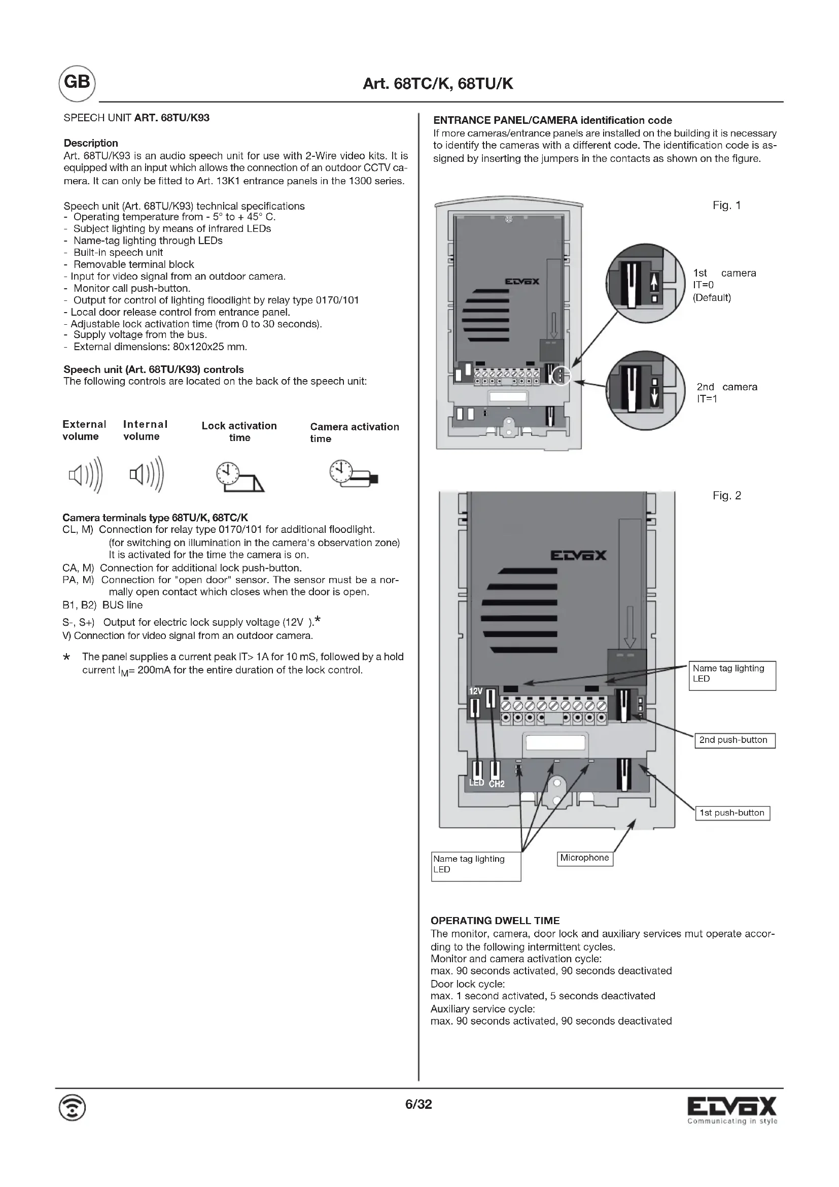
| Identification Code | Configurable by jumpers (IT=0 or IT=1) |
| Installation | Flush or surface mounting on plate Art. 13K1; height approx. 1.65 m from floor |
| Maximum Installation Distance | 150 m between devices (500 m total cable) |
| Recommended Cable | Art. 732H or 732I (2 x 1 mm²) |
| Compliance | European directives 2004/108/EC, 2006/95/EC and subsequent |
| Safety | Use a bipolar switch (contact ≥ 3 mm); do not expose to water |
| Maintenance | Disconnect before cleaning; do not block openings |
| Operating Temperature | Not specified (estimated 0-40°C) |
| Protection Rating | Not specified (IP20 likely) |
Frequently Asked Questions - ELVOX 68TUK93 Vimar
User questions about ELVOX 68TUK93 Vimar
0 question about this device. Answer the ones you know or ask your own.
Ask a new question about this device
Download the instructions for your Intercom in PDF format for free! Find your manual ELVOX 68TUK93 - Vimar and take your electronic device back in hand. On this page are published all the documents necessary for the use of your device. ELVOX 68TUK93 by Vimar.
USER MANUAL ELVOX 68TUK93 Vimar
natural_image
3D technical illustration of an electronic device with labeled ports and wiring (no readable text or symbols)CE

Product is according to EC Directive 2004/108/CE, 2006/95/CE and following norms.
COLLEGAMENTI
Videokit art. 68IA/R (bianco e nero), Art. 68IA/RC (a colori)
Art. 68TU/K93 is an audio speech unit for use with 2-Wire video kits. It is equipped with an input which allows the connection of an outdoor CCTV camera. It can only be fitted to Art. 13K1 entrance panels in the 1300 series.
Speech unit (Art. 68TU/K93) technical specifications
- Operating temperature from - 5° to + 45° C.
- Subject lighting by means of infrared LEDs
- Name-tag lighting through LEDs
- Built-in speech unit
- Removable terminal block
- Input for video signal from an outdoor camera.
- Monitor call push-button.
- Output for control of lighting floodlight by relay type 0170/101
- Local door release control from entrance panel.
- Adjustable lock activation time (from 0 to 30 seconds).
- Supply voltage from the bus.
- External dimensions: 80x120x25 mm.
Speech unit (Art. 68TU/K93) controls
The following controls are located on the back of the speech unit:
| External volume | Internal volume | Lock activation time | Camera activation time |
Camera terminals type 68TU/K, 68TC/K
CL, M) Connection for relay type 0170/101 for additional floodlight. (for switching on illumination in the camera's observation zone) It is activated for the time the camera is on.
CA, M) Connection for additional lock push-button.
PA, M) Connection for "open door" sensor. The sensor must be a normally open contact which closes when the door is open.
B1, B2) BUS line
S-, S+) Output for electric lock supply voltage (12V ).*
V) Connection for video signal from an outdoor camera.
* The panel supplies a current peak IT>1A for 10 mS, followed by a hold current I_M = 200mA for the entire duration of the lock control.
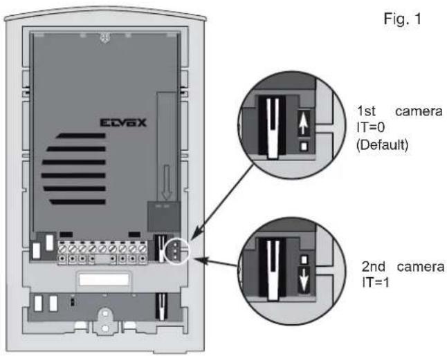
ENTRANCE PANEL/CAMERA identification code
If more cameras/entrance panels are installed on the building it is necessary to identify the cameras with a different code. The identification code is assigned by inserting the jumpers in the contacts as shown on the figure.
OPERATING DWELL TIME
The monitor, camera, door lock and auxiliary services mut operate according to the following intermittent cycles.
Monitor and camera activation cycle:
max. 90 seconds activated, 90 seconds deactivated
Door lock cycle:
max. 1 second activated, 5 seconds deactivated
Auxiliary service cycle:
max. 90 seconds activated, 90 seconds deactivated
INSTALLATION
Installation of entrance panel (type 13K1), flush-mounting version
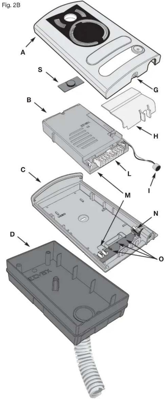
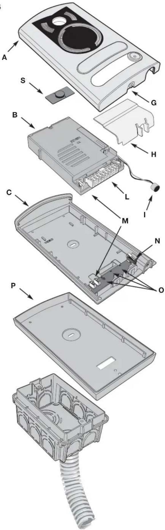
- Install the flush-mounting back box (D) on the wall with the bottom edge at a height of approx. 1.65m from the ground
- Open the entrance panel by loosening the screw underneath the plate (G) and remove the light diffuser (H).
- Fit the frame (C) to the flush-mounting back box (D)
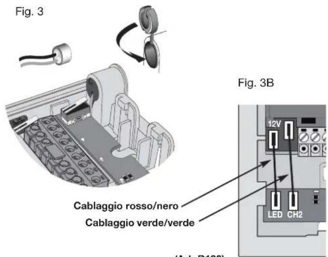
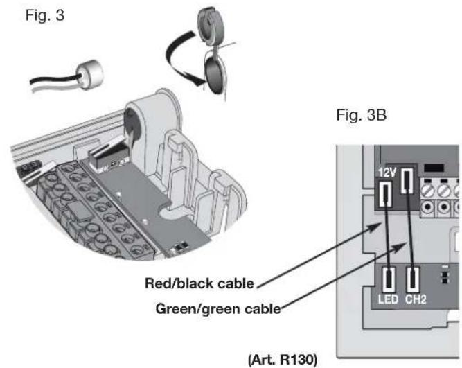
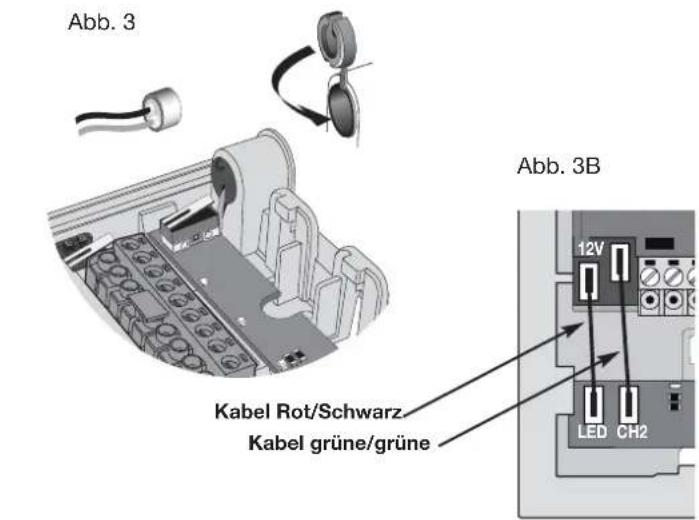
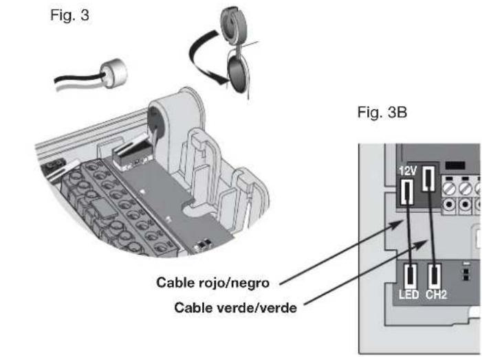
- Reposition the camera in the frame and the microphone in the special housing, refitting the plug as shown in Fig. 3.
- Connect the camera to the name card lighting LED board using the two cable harnesses (harness with red/black wire for LED power supply and harness with two green wires for connection of a second call button, if required) Fig. 3B.
- Make the connections to the installation on the removable terminal block (L).
In the case of installation for two-family video door entry systems:
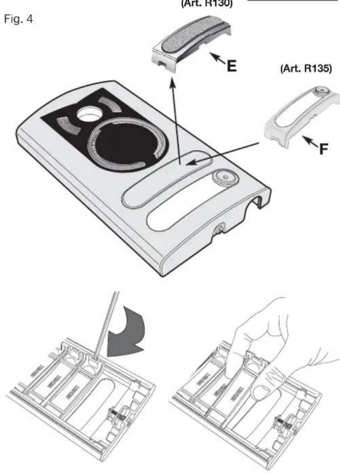
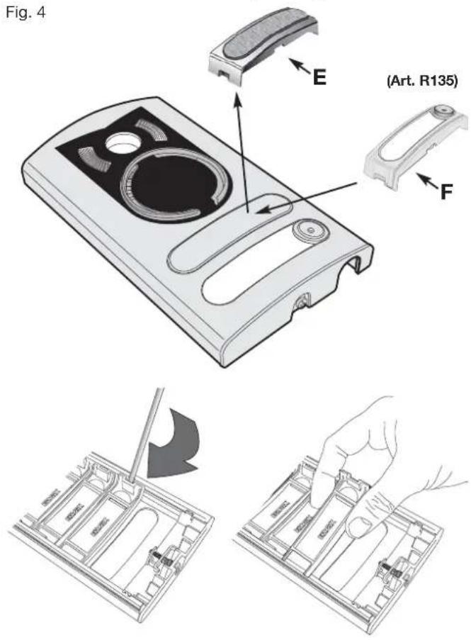
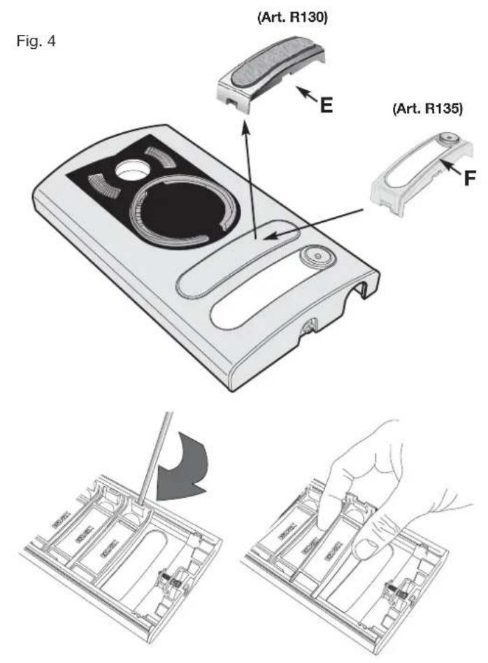
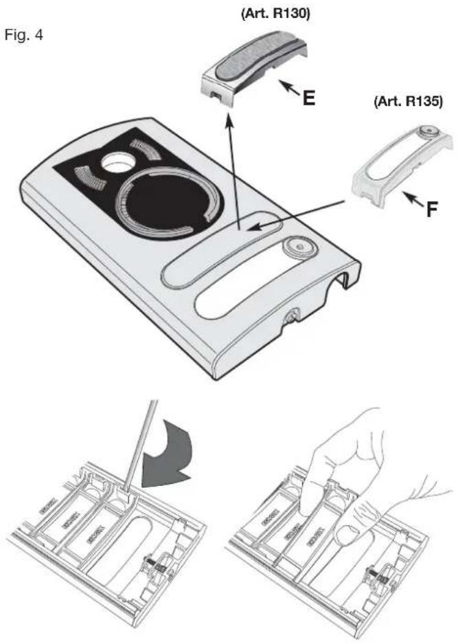
- Remove the blanking module (E) Fig. 4, from the back of the plate using a screwdriver, working in sequence from bottom to top (first remove the end section, then key 1 and finally the blanking module).
- Fit the external key (F) (supplied) to the plate by pushing it lightly into place.
- Insert the light diffuser (H) to ensure even lighting of the name cards.
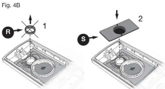
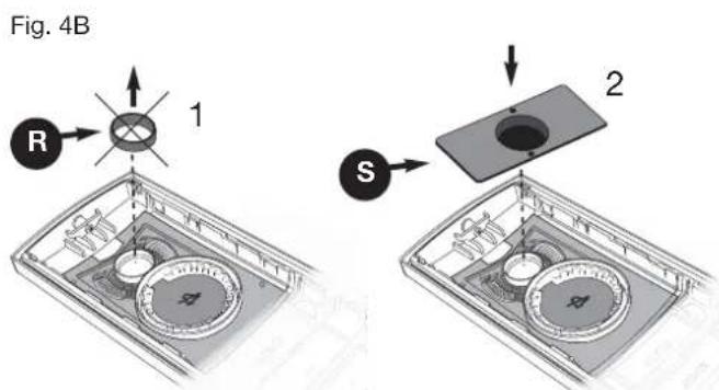
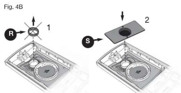
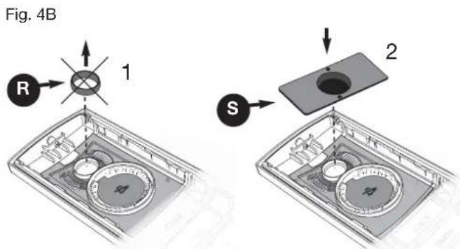
- Remove the lens ring (R) and fit the lens cover (S) (see Fig. 4B).
- Close the entrance panel, securing it to the frame with the aid of a screw-driver.
Installation of entrance panel (type 13K1), surface wall-mounting version
- Open the entrance panel by undoing the screw under the plate (G) and detach the camera (B) from the frame, removing the light diffuser (H) and the microphone (I).
- Install the frame (C) together with the surface wall-mounting back box (P) on the wall with the bottom edge at a height of approx. 1.65m from the ground.
- Reposition the camera in the frame and the microphone in the special housing (B), refitting the plug as shown in Fig. 3.
- Connect the camera to the name card lighting LED board using the two cable harnesses (harness with red/black wire for LED power supply and harness with two green wires for connection of a second call button, if required) Fig. 3B.
- Make the connections to the installation on the removable terminal block (L).
In the case of installation for two-family video door entry systems:
- Remove the blanking module (E) Fig. 4, from the back of the plate using a screwdriver, working in sequence from bottom to top (first remove the end section, then key 1 and finally the blanking module.
- Fit the external key (F) (supplied) to the plate by pushing it lightly into place.
- Insert the light diffuser (H) to ensure even lighting of the name cards.
- Close the entrance panel, securing it to the frame with the aid of a screwdriver.
Fig. 5
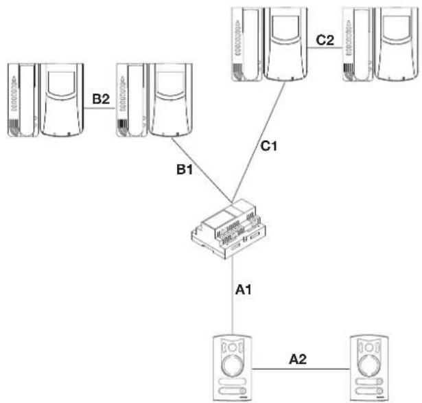
WIRING DIAGRAM
Videokit type 68IA/R (black/white), type 68IA/RC (colour)
- It is possible to reverse the polarity of the two connecting wires between power supply unit and monitor and between power supply unit and entrance panel.
- The cable recommended for connecting the kit is type 732H (2x1mm²) and/or 732I (2x1mm²). If the cable used is not one of those indicated above, the following guarantees do NOT apply.
- The installation is guaranteed up to a maximum distance of 150 metres. Distance intended as the straight-line distance between the 2 devices furthest apart (e.g. the furthest entrance panel and the furthest monitor). The total length of extended cable must not exceed 500 metres. These maximum distances apply to both B/W and colour installations.
- Electric locks connected to the entrance panels must have a maximum input current of 1 A at a voltage of 12 Vdc.
- Electrical disturbances or discharges may affect the operation of the devices. Therefore we recommend laying the cables inside separate tubes.
flowchart
graph TD
    A["Server Units"] -->|B1| C["Switch"]
    B["Server Units"] -->|B2| C
    C -->|C1| D["Server Units"]
    C -->|C2| E["Server Units"]
    C -->|A1| F["Server Units"]
    F -->|A2| G["Server Units"]
A1 + A2 + B1 + B2 = Max 150 m
A1 + A2 + C1 + C2 = Max 150 m
POSTE EXTERNE Art. 68TU/K93
Description
Temps activation camera


Bornes de la caméra Art. 68TU/K, 68TC/K
CONNEXION
SCHALTPLAN
Videoset Art. 68IA/R (S/W), Art. 68IA/RC (Farbe)
CONEXIONADO

LIGAÇÃO
- Carefully read the instructions on this leaflet: they give important information on the safety, use and maintenance of the installation.
- After removing the packing, check the integrity of the set. Packing components (plastic bags, expanded polystyrene etc.) are dangerous for children. Installation must be carried out according to national safety regulations.
- It is convenient to fit close to the supply voltage source a proper bipolar type switch with 3 mm separation (minimum) between contacts.
- Before connecting the set, ensure that the data on the label correspond to those of the mains.
- This apparatus must only be used for the purpose for which it was expressly designed, e.g. for audio or video door entry systems. Any other use may be dangerous. The manufacturer is not responsible for damage caused by improper, erroneous or irrational use.
- Before cleaning or maintenance, disconnect the set.
- In the event of faults and/or malfunctions, disconnect from the power supply immediately by means of the switch and do not tamper with the apparatus.
- For repairs apply only to the technical assistance centre authorized by the manufacturer.
- Safety may be compromised if these instructions are disregarded.
- Do not obstruct opening of ventilation or heat exit slots and do not expose the set to dripping or sprinkling of water. No objects filled with liquids, such as vases, should be placed on the apparatus.
- Installers must ensure that manuals with the above instructions are left on connected units after installation, for users' information.
- All items must only be used for the purposes designed.
- WARNING: to prevent injury, this apparatus must be securely attached to the floor/wall in accordance with the installation instructions.
- This leaflet must always be enclosed with the equipment.

Directive 2002/96/EC (WEEE)
The crossed-out wheelie bin symbol marked on the product indicates that at the end of its useful life, the product must be handled separately
from household refuse and must therefore be assigned to a differentiated collection centre for electrical and electronic equipment or returned to the dealer upon purchase of a new, equivalent item of equipment.
The user is responsible for assigning the equipment, at the end of its life, to the appropriate collection facilities. Suitable differentiated collection, for the purpose of subsequent recycling of decommissioned equipment and environmentally compatible treatment and disposal, helps prevent potential negative effects on health and the environment and promotes the recycling of the materials of which the product is made. For further details regarding the collection systems available, contact your local waste disposal service or the shop from which the equipment was purchased.
Risks connected to substances considered as dangerous (WEEE).
According to the WEEE Directive, substances since long usually used on electric and electronic appliances are considered dangerous for people and the environment. The adequate differentiated collection for the subsequent dispatch of the appliance for the recycling, treatment and dismantling (compatible with the environment) help to avoid possible negative effects on the environment and health and promote the recycling of material with which the product is compound.
CONSEILS POUR L'INSTALLATEUR
Directive 2002/96/CE (WEEE, RAEE)
ELVOX Shanghai Electronics Co. LTD
Room 2616, No. 325 Tianyaoqiao Road
Xuhui District


- COLLEGAMENTI
- Videokit art. 68IA/R (bianco e nero), Art. 68IA/RC (a colori)
- Speech unit (Art. 68TU/K93) controls
- Camera terminals type 68TU/K, 68TC/K
- ENTRANCE PANEL/CAMERA identification code
- OPERATING DWELL TIME
- INSTALLATION
- Installation of entrance panel (type 13K1), flush-mounting version
- Installation of entrance panel (type 13K1), surface wall-mounting version
- WIRING DIAGRAM
- Videokit type 68IA/R (black/white), type 68IA/RC (colour)
- POSTE EXTERNE Art. 68TU/K93
- Description
- Bornes de la caméra Art. 68TU/K, 68TC/K
- CONNEXION
- SCHALTPLAN
- Videoset Art. 68IA/R (S/W), Art. 68IA/RC (Farbe)
- CONEXIONADO
- LIGAÇÃO
- Directive 2002/96/EC (WEEE)
- Risks connected to substances considered as dangerous (WEEE).
- CONSEILS POUR L'INSTALLATEUR
- Directive 2002/96/CE (WEEE, RAEE)
- ELVOX Shanghai Electronics Co. LTD
Brand : Vimar
Model : ELVOX 68TUK93
Category : Intercom