FSRC 3606 GG ED 2F X - Cooker Fulgor Milano - Free user manual and instructions
Find the device manual for free FSRC 3606 GG ED 2F X Fulgor Milano in PDF.

User questions about FSRC 3606 GG ED 2F X Fulgor Milano
0 question about this device. Answer the ones you know or ask your own.
Ask a new question about this device
Download the instructions for your Cooker in PDF format for free! Find your manual FSRC 3606 GG ED 2F X - Fulgor Milano and take your electronic device back in hand. On this page are published all the documents necessary for the use of your device. FSRC 3606 GG ED 2F X by Fulgor Milano.
USER MANUAL FSRC 3606 GG ED 2F X Fulgor Milano
MANUEL D'INSTRUCTIONS
INSTRUCTIEHANDELING
Dear Customer,
Thank you for purchasing one of our Sofia ranges. This range was conceived, designed and handcrafted in Italy.
Your selection of a Sofia range confirms you are among a special group who share a love and passion for cooking. This unique community shares in the experience of creating quality dishes; dishes that will satisfy the palate while bringing the warmth of families and friends together to share and rejoice. Impress a loved one with your ability to combine flavours and ingredients or experiment with new foods and different culinary techniques to create unexpected pleasures.
Giouu/luenghe,
INDICE PAGINA
ACCENSIONE ELETTRICA
1 -Features of your Oven 2
2-Special Warnings 4
Before Starting Installation 4
3-Safety Instructions 5
4- Product Dimensions and Cutout Requirements 8
Anti-Tip Bracket Installation 10
5-Installation Information 11
6-Installation Instructions 12
7-Gas Requirement 14
Instructions for Installation Of The Appliance (Positioning and ventilation requirements) 14
Positioning 14
Ventilation 14
Gas Connection 14
Rigid Pipe Connection 14
8- Conversion to a Different Type of Gas 15
Conversion to a Different Type of Gas 15
Nozzle Table 15
Replace Injectors (two ring flame burner) 17
9-Conversion for LP or NG Gas 18
Replace injector on (oven lower burner) 18
Replace injector on (oven grill burner) 19
Low Flame Adjustment 20
Adjustment for Burners with one or two flame rings: 20
Electric Gas Ignition 21
The Burner Flames 21
10 - Electrical supply 22
Connection to the electrical power mains 22
11 - The Control Panels 23
Control 23
Knobs 23
Signal lamps 23
12 - General Oven Information 24
13 - General Oven Tips 25
Oven Racks 25
Oven Telescopic Racks 26
14- Setting the Clock and Timer 27
Mechanical Minute Timer 27
Timer Touch Control 27
15 - Selecting the Oven Mode 28
16-Cooking In The Oven 29
17-Solving Baking Problems 30
18 - Do-it-Yourself Maintenance Oven Door Removal 31
To Remove Door 31
To Replace Door 31
TABLE OF CONTENTS PAGE
19 - Replacing an Oven Light 32
To Replace a Light Bulb 32
20-Features of your Cooktop 33
21 - Gas Cooktop Operation 34
Gas Control Knob Setting 34
Gas burners 34
Burners with two flame rings 34
22-Gas Cooktop Operation 35
Super Sealed Surface Burners 35
23-Cookware 36
Cookware Characteristics 36
Match Pan Diameter to Flame Size 36
24-General Oven Care 37
How to Use the Oven Cleaning Chart 37
Cleaning Chart 37
25-Oven Finishes/Cleaning Methods 38
26-Cleaning the Cooktop 39
Cooktop Part / Material Suggested Cleaners 39
27 - Solving Operational Problems 41
28- Assistance or Service 42
FEATURES OF YOUR OVEN
MODEL 36"NG (Natural) Gas, 5^ W.C.P LP (Propane) Gas, 10^ W.C.P.
BROIL 14330 Btu/h (4200W) 14330 Btu/h (4200W)
OVEN 17000 Btu/h (5000W) 17000 Btu/h (5000W)
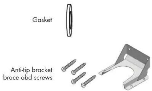
| CONTENTS OF YOUR RANGE PACK | ||||
| QTY DESCRIPTION QTY DESCRIPTION | ||||
| 1 RANGE COOKER 1 FOOT WITH COLLAR | ||||
| 3" BACKPLASH THREE FIXING SCREWS | 1 | ANTI TIP FOUR FIXING SCREWS | ||
| 1 KICK COVER 3 Psc. FOR 36" RANGE | ||||
| 3 FEET | 1 1 | MANUAL & GENERAL DOCUMENTATION "INSTRUCTION MANUAL" GAS CONVERSION KIT | ||
| OVEN ACCESSORIES OF YOUR RANGE | ||||
| QTY DESCRIPTION QTY DESCRIPTION | ||||
| 1 OVEN | 1 | ENAMELED ROASTING PAN | ||
| 2 CHROMED RACKS | 1 | ENAMELED ROASTING PAN GRATE | ||
| 1 | TELESCOPIC CHROMED RACK | |||
EN 2 - SpecialWarnings
IMPORTANT: Save these instructions for the local electrical inspector use.
INSTALLER: Please leave this manual with owner for future reference.
OWNER: Please keep this manual for future reference.
Pay attention to these symbols present in this manual:

DANGER
You can be killed or seriously injured if you don't IMMEDIATELY follow instructions.

WARNING
This is the safety alert symbol. This symbol alerts you to potential hazards that can kill or hurt you and others. You can be killed or seriously injured if you don't follow these instructions.
READ AND SAVE THESE INSTRUCTIONS.
To installer:
Leave these instructions with the appliance.
To customer:
Retain these instructions for future reference.

IMPORTANT INSTRUCTION
Please read all instructions before using this appliance.

Proper installation is your responsibility. Have a qualified technician install this range.

IMPORTANT
- Observe all governing codes and ordinances.
- Write down the model and serial numbers before installing the range. Both numbers are on the serial rating plate refer to the illustration below.
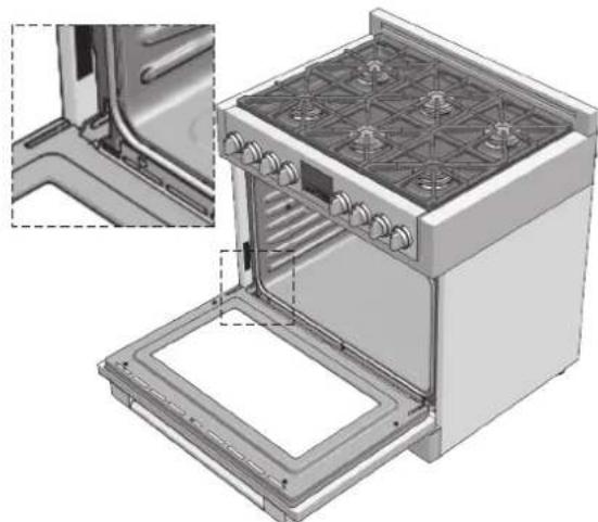
LOCATION OF RATING PLATE
Before Starting Installation
- Check location where range will be installed. The location should be away from strong drafty areas, such as windows, doors and strong heating vents or fans.
- Electrical grounding is required. See "Electrical Requirements"
NOTE: This range is manufactured for use with Natural gas or Propane.
To convert to LP (propane) or NG (natural gas), see instructions in the gas conversion kit provided in the literature package. Proper gas supply connection must be available. See gas supply requirements.

WARNING
Before connecting the appliance to the gas supply line, ensure that its gas setting is appropriate.
The type of gas adjusted and shipped from the factory is indicated on the rating plate.

IMPORTANT
The appliance must be connected by qualified technician in accordance with the applicable regulations. The data plate of the oven is still visible after the appliance has been installed. This plate, which is visible when the oven door is open, contains all the identification data of the appliance, as well the type of gas and service pressure for which it has been calibrated.
Follow the instructions and suggestions carefully to ensure the safe and proper use of this product.

IMPORTANT
THIS APPLIANCE IS CONCEIVED FOR DOMESTICUSEONLY. THE MANUFACTURER SHALL NOT IN ANY WAY BE HELD RESPONSIBLE FOR WHATEVER INJURIES OR DAMAGES ARE CAUSED BY INCORRECT INSTALLATION OR BY UNSUITABLE, WRONG OR ABSURD USE.

IMPORTANT
THIS APPLIANCE IS NOT INTENDED FOR USE BY PERSONS (INCLUDING CHILDREN) WITH REDUCED PHYSICAL, SENSORY OR MENTAL CAPABILITIES, OR LACK OF EXPERIENCE AND KNOWLEDGE, UNLESS THEY HAVE BEEN GIVEN SUPERVISION OR INSTRUCTION CONCERNING USE OF THE APPLIANCE BY A PERSON RESPONSIBLE FOR THEIR SAFETY.
CHILDREN SHOULD BE SUPERVISED TO ENSURE THAT THEY DO NOT PLAY WITH THE APPLIANCE.
- Do not disassemble any parts prior to having disconnected the Range from the mains.
- Do not use the appliance if any part is broken (for example a glass). Disconnect it from the mains and call service.
- Before using the oven, it is recommended to make it operate at nolog at the maximum temperature for an hour to eliminate the insulating material odour.
- In all models, leave the door closed when the grill is used.
- The cooling fan may remain in operation so long as the oven is hot, even after it has been switched off.
- During the use the appliance becomes very hot; don't touch the heating elements inside the oven.
- During the oven operation, the front is heated as well; consequently keep children clear of the oven.
- Parents and adults should pay particular attention when using the product in presence of children.
Children should be overseen so as to ensure that they don't play with the equipment. - Keep children under age 8 away, unless constantly supervised.
-
This appliance is not intended for use by persons (including children over age 8) with reduced physical sensory or mental capabilities, or lack of experience and knowledge, unless they have been given supervision or instruction concerning use of the appliance by a person responsible for their safety.
Children may not perform cleaning and maintenance unsupervised. -
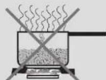
In order to avoid damage to the oven enamel coat, do not cover the oven muffle sole with any item (e.g. aluminum foil, pans and the likes).
- Do not use harsh abrasive cleaners or sharp metal scrapers to clean the oven door glass since they can scratch the surface, which may result in shattering of the glass.
- Abrasive detergents and steam cleaning equipment should not be used for cleaning.
- The oven is cool and power to the oven has been turned off before removing the door. Failure to do so could result in electrical shock or burns.
- The appliance must not be installed behind a decorative door in order to avoid overheating.

WARNING
Ensure that the appliance is switched off before replacing the lamp to avoid the possibility of electric shock.
- Prolonged intensive use of the appliance may call for additional ventilation, for example opening of a window, or more effective ventilation increasing the level of mechanical ventilation where present.
- Prior to installation, ensure that the local distribution conditions (nature of the gas and gas pressure) and the adjustment of the appliance are compatible.
- Do not use cooking vessels or pans on the hotplate that overlap its edges.
To reduce the risk of burn injuries during cooktop use, observe the following:
Children or pets should not be left alone or unattended in an area where appliances are in use.
Children should never be allowed to sit or stand on any part of the appliance.
- Do not store flammable materials on or near the cooktop.
- When using the cooktop: DO NOT TOUCH THE BURNER GRATES OR THE IMMEDIATE SURROUNDING AREA.
- Use only dry potholders; moist or damp potholders on hot surfaces may cause burns from steam.
- Never leave the cooktop unattended when in use.
- Boilovers cause smoking, and greasy spillovers may ignite. A spill on a burner can smother all or part of the flame or hinder spark ignition. If a boilover occurs, turn off burner and check operation. If burner is operating normally, turn it back on.
- During cooking, set the burner control so that the flame heats only the bottom of the pan and does not extend beyond the bottom of the pan.
- Take care that drafts like those from fans or forced air vents do not blow flammable material toward the flames or push the flames so that they extend beyond the edges of the pan.
- Always position handles of utensils inward so they do not extend over adjacent work areas, burners, or the edge of the cooktop.
- Wear proper apparel. Loose fitting garments or hanging sleeves should never be worn while cooking.
- Never let clothing, potholders, or other flammable materials come in contact with hot burners or hot burner grates.
- Use only certain types of glass, heatproof glass ceramic, ceramic, earthenware, or other glazed utensils that are suitable for cooktop use.
- Do not clean the cooktop while it is still hot. Some cleaners produce noxious fumes when applied to a hot surface.

CAUTION
Do not allow aluminium foil, plastic, paper or cloth to come in contact with hot burners or grates. Do not allow pans to boil dry.

CAUTION
Do not store items of interest to children above the appliance. If children should climb onto the appliance to reach these items, they could be seriously injured.
To reduce the risk of fire in the oven cavity:
- Do not store flammable materials in or near the oven.
- Do not use water on a grease fire. Smother fire or use a dry chemical or foam-type extinguisher.
- It is highly recommended that a fire extinguisher be readily available and highly visible next to any cooking appliance.
- Do not overcook food. Carefully attend oven if paper, plastic or other combustible materials are placed inside the oven.
- Do not use the cavity for storage purposes. Do not leave paper products, cooking utensils or food in the cavity when not being used.
- If materials inside the oven should ignite, keep oven door closed. Turn oven off and disconnect the circuit at the circuit breaker box.
- Do not block any vent openings.
- Be sure the blower fan runs whenever the oven is in operation. If the fan does not operate, do not use the oven. Call an authorized service center.
- For personal safety, wear proper clothing. Loose fitting or garments with hanging sleeves should never be worn while using this appliance.
- Tie long hair so that it doesn't hang loose.
- Do not touch interior surfaces of oven.
- During and after use, do not touch or let clothing or other flammable materials contact the burners or the interior surfaces of the oven until they have had sufficient time to cool. Other surfaces of the appliance may become hot enough to cause burns for example, oven vent openings and surfaces near these openings, oven doors, and windows of oven doors.
- The trim on the top and sides of the oven door may become hot enough to cause burns.
- Use care when opening the door. Open the door slightly to let hot air or steam escape before removing or replacing food.
- Do not heat unopened food containers. Build-up of pressure may cause the container to burst and cause injury.
- Always place oven racks in desired location while oven is cool. If a rack must be moved while oven is hot, do not let pot holder contact the hot heating elements.
- Use only dry pot holders. Moist or damp pot holders on hot surfaces may result in burns from steam. Do not let pot holder touch burners. Do not use a towel or other bulky cloth.

WARNING
- For proper lighting and performance of the burners, keep the igniters clean and dry.
- In the event that a burner goes out and gas escapes, open a window or a door. Wait at least 5 minutes before using the cooktop.
- Do not obstruct the flow of combustion and ventilation air.
- Do not use aluminium foil to line any part of the oven cavity as it will fuse to and ruin the enamel during cooking.
- If the range cookers is near a window, be certain blow over or near the burners; they could catch on fire.
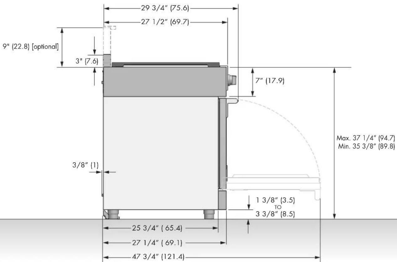
EN 4 - Product Dimensions and Cutout Requirements
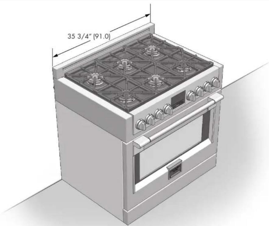
PRODUCT DIMENSIONS
36" Wide Range Models
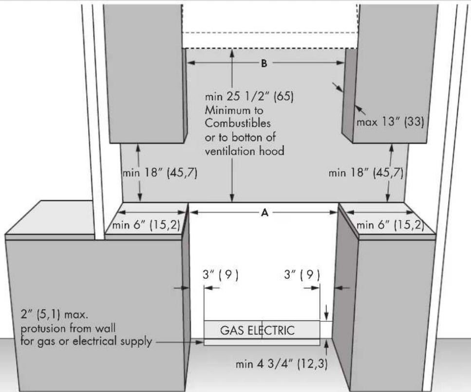
CUTOUT REQUIREMENTS
The surface of the entire back wall above the range and below the hood must be covered with a noncombustible material.
*Consult local code for exact location requirements.
OPENINGWIDTHA&B
Range 36^ 36^ (91.4)
Minimum clearances:
Above cooking surface (above 36^ [91.4cm] )
- Sides - 6" (15.2 cm)
- Within 6'' (15.2 cm) side clearance, wall cabinets no deeper than 13'' (33.0 cm) must be minimum 18'' (45.7 cm) above cooking surface
- Rear - 0" with 9 " backguard; 0" with non-combustible rear wall.
Below cooking surface (36^ [91.4cm] and below
- Install with zero clearance between adjacent combustible construction below the cooking surface and the back and sides of the appliance.

CAUTION
Pro style gas ranges exhaust oven combustion air through the rear back guard. Therefore certain cooking conditions may result in staining or discoloration of the backsplash. Always choose a back splash material that is suitable for this application as Fulgor Milano will not be held responsible for the discoloration of back splash.
EN 4 - Product Dimensions and Cutout Requirements
Before moving the range, protect any finished flooring and secure oven door(s) closed to prevent damage.
Vent hood Combinations:
It is recommended that these ranges be installed in conjunction with a suitable overhead vent hood.
Due to the high heat capacity of this unit, particular attention should be paid to the hood and ductwork installation to assure it meets local building codes.

WARNING
Air curtain or other overhead hoods, which operate by blowing a downward air flow on to a range, shall not be used in conjunction with ranges with gas cooktop other than when the hood and range have been designed, tested and certified by an independent test laboratory for use in combination with each other.
Clearances to horizontal surfaces above the range, measured to the cooking surface are below. Failure to comply may result in fire hazard.
- A custom hood installation with exposed horizontal combustible surfaces must have an Auto-On feature.
- For other installations with a hood, refer to the hood installation instructions for specific hood clearances.

CAUTION
These ranges weigh up to 400 pounds (180Kg). Some disassembly will reduce the weight considerably. Due to the weight and size of the range and to reduce the risk of personal injury or damage to the product:
TWO PEOPLE ARE REQUIRED FOR PROPER INSTALLATION.
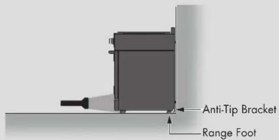
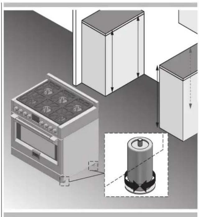
Anti-Tip Bracket Installation

WARNING
Tip Over Hazard
A child or adult can tip the range and be killed.
Ensure the anti-tip bracket is engaged when the range is moved.
Do not operate range without anti-tip bracket installed and engaged.
Failure to follow these instructions can result in death or serious burns to children and adults.


WARNING
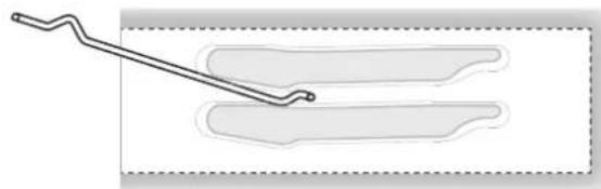
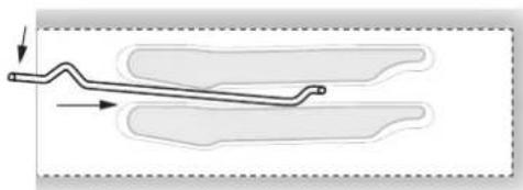
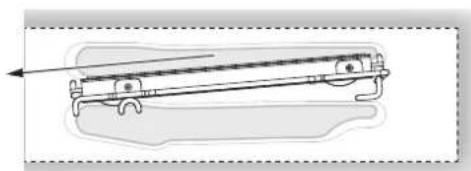
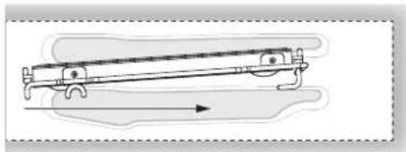
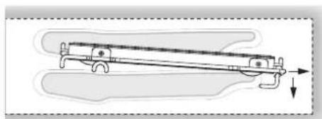
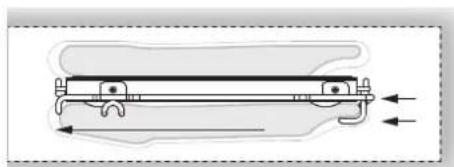
To verify the anti-tip bracket is installed and engaged:
- Slide range forward.
- Look for the anti-tip bracket securely attached to floor or wall.
- Slide range back so rear range foot is under anti-tip bracket.
See installation instructions for details.
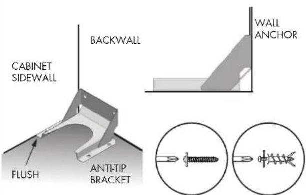
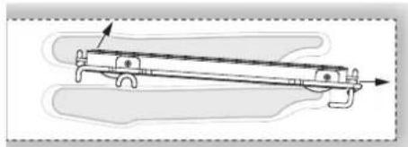
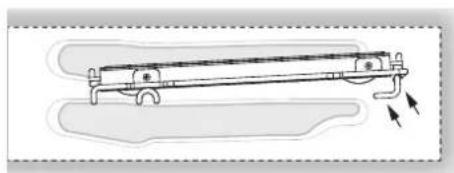
ANTI-TIP BRACKET INSTALLATION
For Concrete or Cement Construction:
You must use appropriate fastening hardware (not provided).
Secure the bracket to the wall and/or floor with at least 4 wood screws (provided).
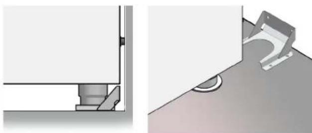
The anti-tip bracket should be inserted into the opening on the anti-tip brace on the range.

WARNING
- Excessive Weight Hazard
Use two or more people to move and install range. Failure to do so can result in back or other injury.
Cut Hazard
Beware of sharp edges. Use the polystyrene ends when carrying the product. Failure to use caution could result in minor injury or cuts.
Do not obstruct the flow of combustion air at the oven vent nor around the base or beneath the lower front panel of the range. Avoid touching the vent openings or nearby surfaces as they may become hot while the oven is in operation. This range requires fresh air for proper burner combustion. NEVER cover any slots, holes or passages in the oven or cover an entire rack with aluminum foil. Doing so blocks air flow through the oven and may cause carbon monoxide poisoning. Aluminum foil linings may also trap heat, causing a fire hazard.
CHOOSING RANGE LOCATION
Carefully select the location where the range will be placed. The range should be located for convenient use in the kitchen, but away from strong drafts. Strong drafts may be caused by open doors or windows, or by heating and/or air conditioning vents or fans.

IMPORTANT NOTE
When installing against a combustible surface, a minimum riser is required for a the range, Follow all minimum clearances to combustible surfaces shown in the illustration on the previous pages.
Before moving the range, protect any finished flooring and secure oven door(s) closed to prevent damage.
Do not lift or carry the range door by the door handle.
To eliminate the risk of burns or fire by reaching over heated surface units, cabinet storage space located above the surface units should be avoided. If cabinet storage is to be provided, the risk can be reduced by installing a range hood that projects horizontally a minimum of inches beyond the bottom of the cabinets.
All openings in the wall or floor where the range is to be installed must be sealed.
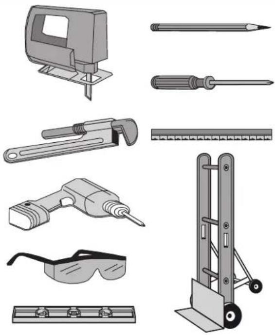
TOOLS WILL YOU NEED
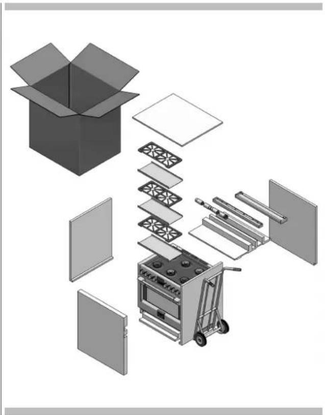
Remove packaging materials and literature package from the cooktop before beginning installation.
Remove Installation Instructions from the literature pack and read them carefully before you begin
MATERIALS PROVIDED
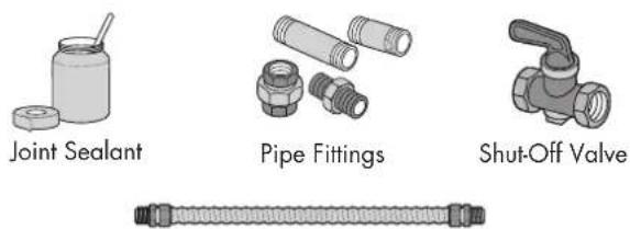
MATERIALS REQUIRED (not provided)
NOTE: Purchase new flexible line; do not use previously used flexible gas line.
EN 6 - Installation Instructions
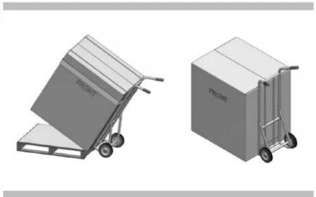
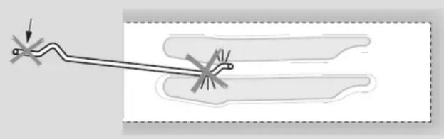
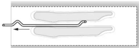
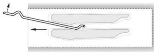
STEP1
Cut the banding and remove the appliance from the pallet by a hand-truck inserting the blade under the foam base.

CAUTION
Stand clear. The ends of the cut banding may snap toward you.
STEP2
Remove Installation Instructions from the top of range and read them carefully before you begin.
STEP3
Move the range indoors before installing the legs, position the appliance near its final location as the legs are not suitable for moving the appliance over long distances.
Legs are packed in the cardboard top pack.

CAUTION
Doors and passageways leading to the installation location require at least 31^ (79cm) opening. If the opening is less than 31^ (79cm), the oven door(s) and control knobs must be removed.
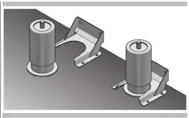
Note: the legs with collar must be mounted on the back of range to engage the anti tip device.
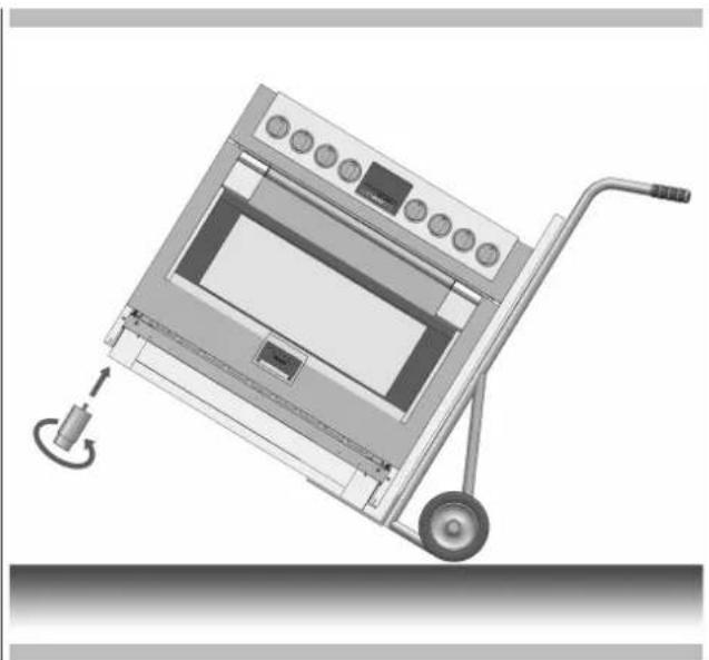
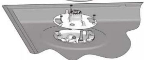
STEP4
With the foam base still in place, tilt the range laterally and screw in the first pair of legs.
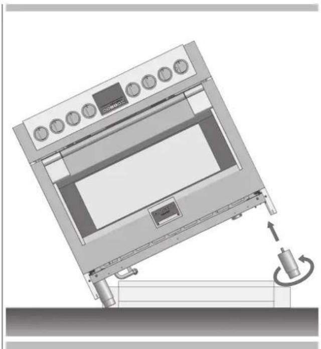
STEP5
Pull out the hand-truck, tilt the range laterally and insert the second pair of legs. Remove the base
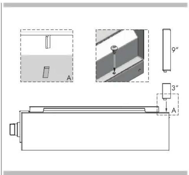
STEP6
Install the backsplash (if provided) by the three screws on the back and the toe kick
STEP7
After the electrical and gas connections (see the paragraph for instructions) measure the four corners in cutout area to verify if flooring is level. Adjust the leveling legs to the desired height and ensure range is level. Turn the bottom section of each leg counterclockwise to raise the leg and clock wise to lower it. Ensure floor is protected. Slide unit into place making sure to engage the anti-tip bracket.
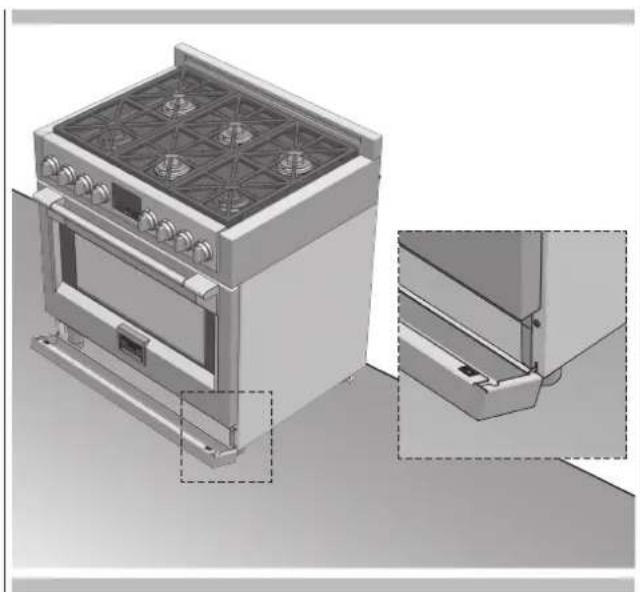
STEP8
Hook tabs on bottom of toekick into slots on either side of the frame and rotate up until clips at top of toekick engage securely.
NOTE: Be sure the toekick snaps securely.
QUALIFIED SERVICE MAN OR GAS APPLIANCE INSTALLER MUST MAKE THE GAS SUPPLY CONNECTION.
Leak testing of the appliance shall be conducted by the installer according to the instructions given.
Instructions for Installation Of The Appliance (Positioning and ventilation requirements)
The regulations covering the installation, maintenance and operation of gas appliances for domestic use are applicable regulations.
An extract of these regulations appears below. For all indications not covered, refer to the above-mentioned regulations.
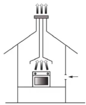
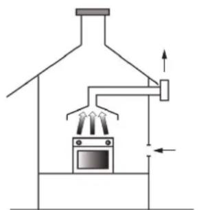
Positioning
The products of combustion from cooking appliances must always be discharged into suitable extractor hoods, which must be connected to a chimney, flue or vented directly to outside the building. In situations where it is not possible to install an extractor hood, an electric extractor fan installed in a window or external wall may be used, provided that all requirements of the ventilation regulations are satisfied; the fan should switch on whenever the appliance is in operation.
VENTILATION
Ventilation
It is essential that the room in which gas appliances are installed is adequately ventilated to ensure that all the appliances receive the required quantity of fresh air for combustion.
To ensure an adequate air flow, it may be necessary to create apertures in accordance with the following requirements:
a) with cross-sectional area of 6cm^2 per kW with a minimum cross-sectional area of 100 cm² (these apertures may also be created by increasing the gap between the bottom of doors and the floor);
b) situated at the bottom of an external wall, preferably opposite the wall on which combustion products are extracted;
c) the positions of the apertures should be selected so as to avoid the possibility of their being obstructed and, if made in external walls, they must be protected with grilles, metal meshes, etc. installed on the outside face of the wall.
If an electric extractor fan for the removal of foul air is installed in the room, the apertures provided for air changes must allow a ventilation rate of at least 35m^3 /h per kW of power installed.
Gas Connection
The oven is designed to operate with both natural gas (methane) and liquid gas (LPG), and can be easily converted from one type to another following the instructions given in the relative section of this booklet.
Connection to the gas supply must be carried out by qualified technicians and in conformance with the requirements.
If the appliance is to operate with gas bottles (LPG), a pressure regulator conforming to the requirements.
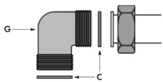
Rigid Pipe Connection
Connection to the mains gas supply may be made via a rigid pipe firmly attached to the fitting "G", or via a flexible stainless steel continuous-wall hose, conforming with a maximum length of 2 metres.
The fitting "G" and seal "C" are supplied with the appliance, and comply with standards.

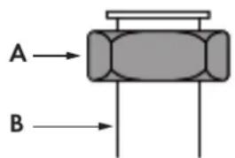
IMPORTANT
Use two wrenches to turn the fitting "G" to the required position. When the fitting is in the desired position, firmly tighten nut "A".
RIGID PIPE CONNECTION

IMPORTANT
After connecting the appliance to the gas supply (or to the liquid gas bottles) CHECK FOR LEAKS at the union using a solution of soapy water (never use a naked flame).
Conversion to a Different Type of Gas
Before converting the appliance for operation with a different gas type, check which type of gas it is currently set to operate with (adhesive label (Figure 1) on appliance).
Disconnect the electrical power supply to the appliance; For the correct nozzle diameter, refer to the relative table in this booklet.
Nozzle Table
The diameters in hundreds of millimetre are stamped on the nozzle.
| Top burner LP | ||||
| Nominal heat input kW 4,50 4,50 4,50 4,50 | ||||
| Inner ring injector size 37 37 34 32 | ||||
| Outer ring injector size 98 98 94 90 | ||||
| Consumption 328 g/h 328 g/h 328 g/h 328 g/h | ||||
| Oven | ||||
| Nominal heat input kW 5,00 5,00 5,00 5,00 | ||||
| Injector size 110 | 110 | 105 | 98 | |
| Consumption 365 g/h 365 g/h 365 g/h 365 g/h | ||||
| Grill | ||||
| Nominal heat input kW 4,20 4,20 4,20 4,20 | ||||
| Injector size 105 | 105 | 95 90 | ||
| Consumption 306 g/h 306 g/h 306 g/h 306 g/h | ||||
| Gas family | 3+ | 3B/P | 3B/P | 3B/P |
| Gas | "G30 G31" | "G30 G31" | "G30 G31" | "G30 G31" |
| Gas pressure | "28...30 37" | 30 | 37 | 50 |
| AT | x | |||
| BE | x | |||
| BG | x | |||
| CH | x | x | ||
| CY | x | x | ||
| CZ | x | |||
| DE | x | |||
| DK | x | |||
| EE | x | |||
| ES | x | |||
| FI | x | |||
| FR | x | |||
| GB | x | |||
| GR | x | x | ||
| HU | x | |||
| IE | x | |||
| IS | x | |||
| IT | x | |||
| LT | x | x | ||
| LU | ||||
| LV | x | |||
| MT | x | |||
| NL | x | |||
| NO | x | |||
| PL | x | |||
| PT | x | |||
| RO | x | |||
| SE | x | |||
| SI | x | x | ||
| SK | x | x | x | |
| AL | x | x | ||
| HR | x | |||
| MK | x | x | ||
| TR | x | x | ||
EN 8 - Conversion to a Different Type of Gas
| Top burner NG | |||||||||
| Nominal heat input kW 4,50 4,50 4,50 4,50 4,50 4,50 4,50 4,50 4,50 4,50 4,50 4,50 4,50 4,50 4,50 4,50 4,50 4,50 4,50 4,50 4,51 | |||||||||
| Inner ring injector size 55 55 55 58 57 57 59 57 74 57 | |||||||||
| Outer ring injector size 14 3 143 143 147 160 160 135 152 200 165 | |||||||||
| Consumption 429 l/h 429 | l/h 429 | l/h 429 l/h | 429 l/h | 429 l/h | 429 l/h | 429 l/h | 429 l/h | 429 l/h | 429 l/h |
| Oven | |||||||||
| Nominal heat input kW 5,00 5,00 5,00 5,00 5,00 5,00 5,00 5,00 5,00 5,00 5,00 | |||||||||
| Injector size 155 155 155 | 160 168 | 168 146 | 165 240 | 180 | |||||
| Consumption 476 l/h 476 | l/h 476 | l/h 476 l/h | 476 l/h | 476 l/h | 476 l/h | 476 l/h | 476 l/h | 476 l/h | |
| Grill | |||||||||
| Nominal heat input kW 4,20 4,20 4,20 4,20 4,20 4,20 4,20 4,20 4,20 4,20 4,20 4,20 4,20 4,20 4,20 4,20 4,20 4,20 4,20 4,20 4,2 | 150 150 150 150 150 150 150 150 150 150 150 150 150 150 150 150 150 150 150 150 150 150 150 150 150 150 | 160 168 | 168 146 | 165 240 | 180 | ||||
| Injection size 150 150 150 150 150 150 150 150 150 150 150 150 150 150 150 150 150 150 150 150 150 150 150 150 15 | 153 162 | 162 143 | 158 200 | 162 | |||||
| Consumption 400 l/h 400 l/h 400 l/h 400 l/h 400 l/h 400 l/h 400 l/h 400 l/h 400 l/h 400 l/h 400 l/h 400 l/h 400 l/h 400 l/h 400 l/h 400 l/h 400 l/h 40 | 150 150 150 150 150 150 150 150 150 150 150 150 150 150 150 150 150 150 150 150 150 150 150 150 15 | 20 20 | 20 20 | 20 20 | 20 20 | 20 20 | 20 20 | 20 20 | |
| Gas family | 2H | 2E | 2E+ | 2K | 2L | 2LL | 2H | 2S | 2Lw |
| Gas | G20 G20 | "G20 G25" | G25.3 | G25 G25 | G20 G25 | 1 | G2.3 | G27 | |
| Gas pressure | 20 20 | "20 25" | 25 20 | 20 25 25 | 13 20 | ||||
| AT x | |||||||||
| BE | x | ||||||||
| BG | x | ||||||||
| CH | x | ||||||||
| CY | x | ||||||||
| CZ | x | ||||||||
| DE | x | x | |||||||
| DK | x | ||||||||
| EE | x | ||||||||
| ES | |||||||||
| FI | x | ||||||||
| FR | x | ||||||||
| GB | x | ||||||||
| GR | x | ||||||||
| HU | x | x | |||||||
| IE | x | ||||||||
| IS | |||||||||
| IT | x | ||||||||
| LT x | |||||||||
| LU | x | ||||||||
| LV x | |||||||||
| MT | |||||||||
| NL | x | ||||||||
| NO | x | ||||||||
| PL | x | x | |||||||
| PT | x | ||||||||
| RO | x | x | |||||||
| SE | x | ||||||||
| SI | x | ||||||||
| SK | x | ||||||||
| AL | x | ||||||||
| HR | x | ||||||||
| MK | x | ||||||||
| TR | x | ||||||||
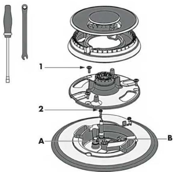
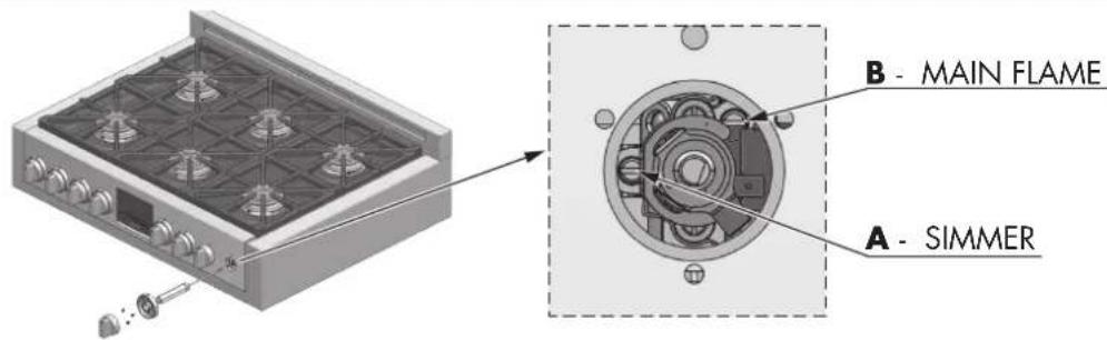
Replace Injectors (two ring flame burner)
- Remove the grates and burner caps.
- Remove aluminium gas spreader.
- Remove the three screws from the simmer gas spreader (1).
- Remove the two screws of the injector cover (2).
- Remove injector (A) by using a 9-32" (7mm) nut driver counter clockwise.
- Remove injector (B) by using a 9-32" (7mm) box wrench counter clockwise.
- Install the injectors supplied with this appliance in the appropriate burner. The injectors have small numbers stamped on the side, this number corresponds with the orifice diameter and its correct burner location (refer to illustrations in the section: "Injectors Position").
- Turn clockwise to tighten (tighten to a torque of 15 to 20 inch-lbs).
- Replace all parts following the reverse order.
- Save the injectors removed from the appliances for future use.
EXPLODED VIEW OF BURNER
EN 9 - Conversion for LP or NG Gas
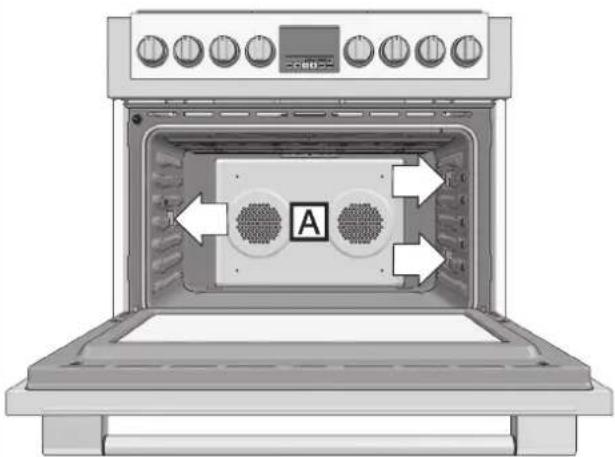
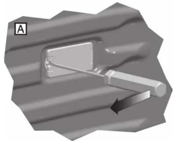
Replace injector on (oven lower burner)
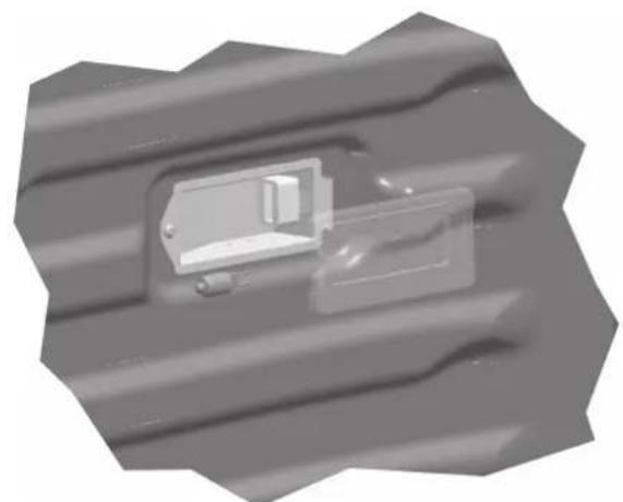
- Remove the burner cover plate.
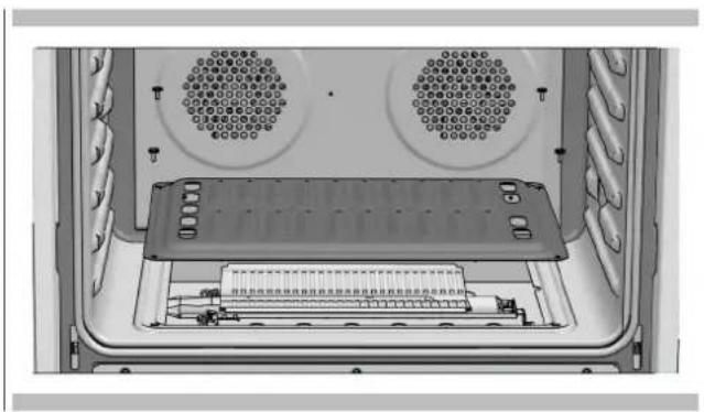
- Disconnect both heat sensor and the ignition spark plug.
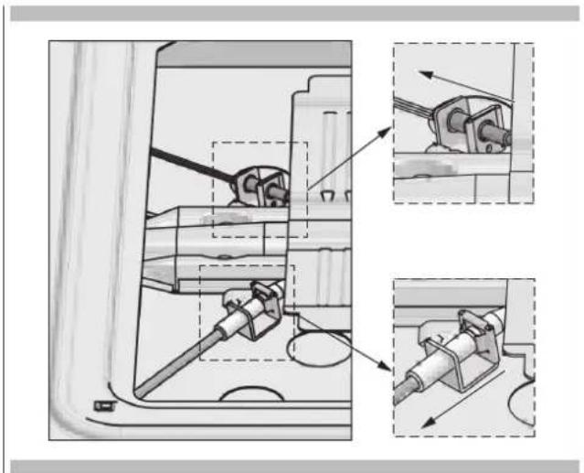
- Remove the screw securing the oven burner and withdraw the burner from the support.
- Remove the nozzle by turning 9 - 32^ (7 mm) nut driver counter clockwise.
- Install the injectors supplied with this appliances in the appropriate burner. The injectors have small number stamped on the side, this number codes the orifice diameter and its correct burner location (see figure of the paragraph "Injectors position").
- Turn clockwise to tighten (tighten to a torque of 15 to 20 inch-lbs - 1.7 to 2.2 Nm).
- Replace all parts following the reverse order. Save the injectors removed from the appliances for future use.
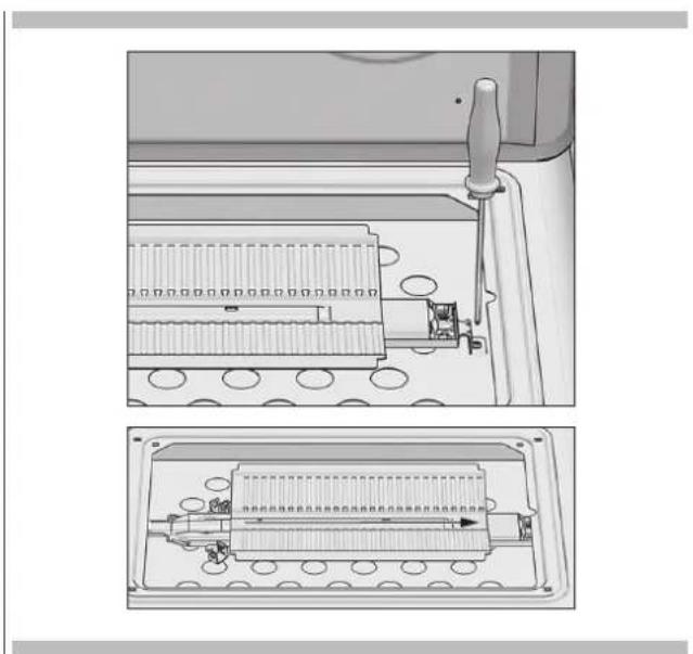
Replace injector on (oven grill burner)
- Remove the door as described in the paragraph "Door removal"
- Remove the screws securing the grill burner and withdraw the burner from the support.
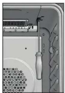
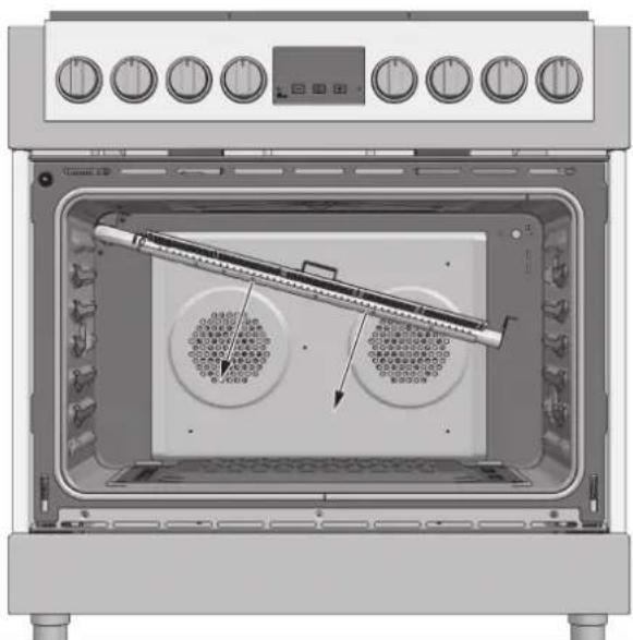
- Remove the nozzle by turning 9 - 32^ (7 mm) nut driver counter clockwise.
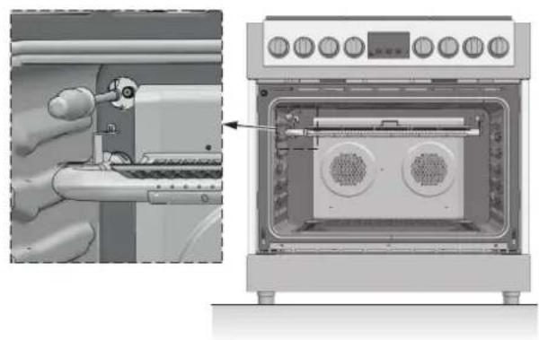
- Install the injectors supplied with this appliances in the appropriate burner. The injectors have small number stamped on the side, this number codes the orifice diameter and its correct burner location (see figure of the paragraph "Injectors position").
- Turn clockwise to tighten (tighten to a torque of 15 to 20 inch-lbs - 1,7 to 2,2 Nm))
- Replace all parts following the reverse order paying attention to the correct placement of the burner.
- Save the injectors removed from the appliances for future use.
EN 9 - Conversion for LP or NG Gas
Low Flame Adjustment

DANGER
Lighting gas burners with a match is dangerous.
You should match light the burners only in an emergency.
Light a match and hold the flame near the burner you want to light.Wooden matches work best.
Push in and turn the control knob slowly.
Be sure you are turning the correct knob for the burner you are lighting.
NOTE: If the burner does not light within five seconds, turn the knob off and wait one minute before trying again.

CAUTION
If you attempt to measure the inner cone of the flame, please use caution. Burns could result.
This appliance is shipped from the factory with low and medium flame settings adjusted. If further adjustment is necessary, proceed as follows:
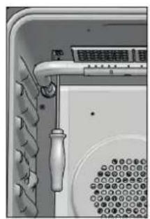
Adjustment for Burners with one or two flame rings:
- Light burner and set control knob for low flame.
- Remove control knob from valve stem.
-
Remove knob seat from control panel.
-
Insert a slender, thin-blade screwdriver into the recess behind the control knob (A or B) and engage blade with slot in adjusting screw.
-
Turn adjusting screw to set flame size:
-
clockwise to reduce
counterclockwise to increase -
Replace control knob when adjustment is completed.
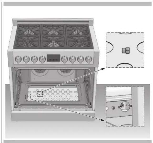
Adjustment for Lower Oven Burner:
- Light burner and set control knob for low flame.
- Remove control knob from valve stem.
Conversion from natural gas to liquid gas
- insert the screwdriver in the hole in the front wall of the instrument panel and turn regulation screw A clockwise.
Conversion from liquid gas to natural gas
- Light the oven with thermostat set to 250^ for at least 10-15 minutes.
Then, turn the thermostat to the minimum position and turn the bypass screw A counterclockwise until you see a reduced by stable flame.
NOTE: Check that the flame does not go out when the door of the oven is opened and closed repeatedly. If the flame goes out, slight increase the minimum regulation setting.
5. Replace control knob when adjustment is completed.
ADJUSTMENT FOR COOKTTOP BURNERS
ADJUSTMENT FOR LOWER OVEN BURNER
Proper adjustment will produce a stable, steady blue flame of minimum size.
The final adjustment should be checked by turning the knob from high to low several times without extinguishing the flame. This adjustment, at low setting, will automatically provide the proper flame size at medium setting.
After Conversion steps have been completed, check the appearance of each burner's flame at the HI and LO settings, if the flames appear too large or too small
review each step to make sure it was completed correctly.
NOTE: To obtain the correct minimum setting with LP gas, turn clockwise tightening the valve(s) fully with the thin-blade screwdriver into the recess behind control knob (A and / or B).
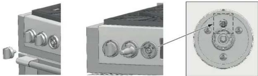
Electric Gas Ignition
The gas burners use an electric ignition device located near each burner ensures burners ignite automatically.
ELECTRIC IGNITION
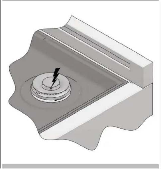
See Use & Care paragraph for better explanation and its control.
The Burner Flames
Turn each burner on. Flames should be blue in color with no trace of yellow. The burner flames should not flutter or blow away from the burner. The inner cone of the flame should be between 1/2'' and 3/4'' long.
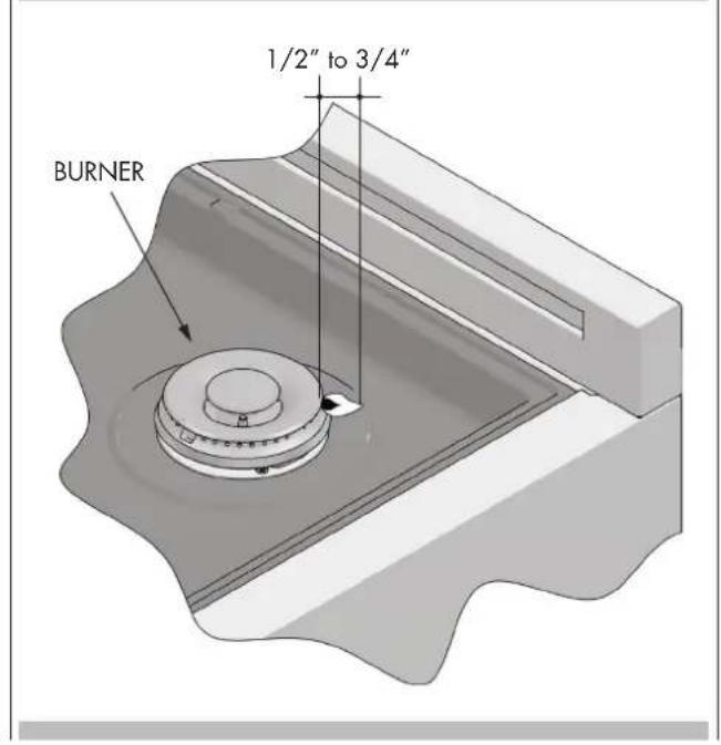
BURNER FLAMES
Connection to the electrical power mains

WARNING
This apparatus must be earthed.
The oven is only for domestic use.
The feed voltage and the absorbed power are as indicated on the data plate attached to the left-hand side upright, which can be seen when the oven door is open.
Connecting must be carried out by qualified personnel and in accordance with the regulations currently in force.
The manufacturer can not be held responsible for any damages to persons or objects caused by failure to observe these instructions.
If the supply cord is damaged, it must be replaced by the manufacturer, its service agent or similarly qualified persons in order to avoid a hazard.
The oven must be connected to the mains through a multipole circuit breaker with a contact-to-contact gap of at least 3 mm, making sure that the earth wire is not disconnected. For connecting use a flexible cable remembering to make it long enough to allow the oven to be removed from its housing unit when maintenance work is required.
The terminal box is located at the rear of the appliance. If a new cable is fitted, route it through the clamp and make the connections as shown in the diagram. The earth wire must be cut longer than the other wires so that it will be the last to break off in the event of the cable being tugged.
Having made the connection, tighten the cable clamp and close the cover of the box.
CABLE TYPES AND MINIMAL DIAMETERS CABLE TYPES AND MINIMAL DIAMETERS
| H05RR-F 3x1 mm | 2 |
| H05VV-F 3x1 mm | 2 |
| H05RN-F 3x1 mm | 2 |
| H05V2V2-F 3x1 mm | 2 |
The user interface has the following features: display, preheat light indicators, keys for commands, cooking mode and temperature selectors.
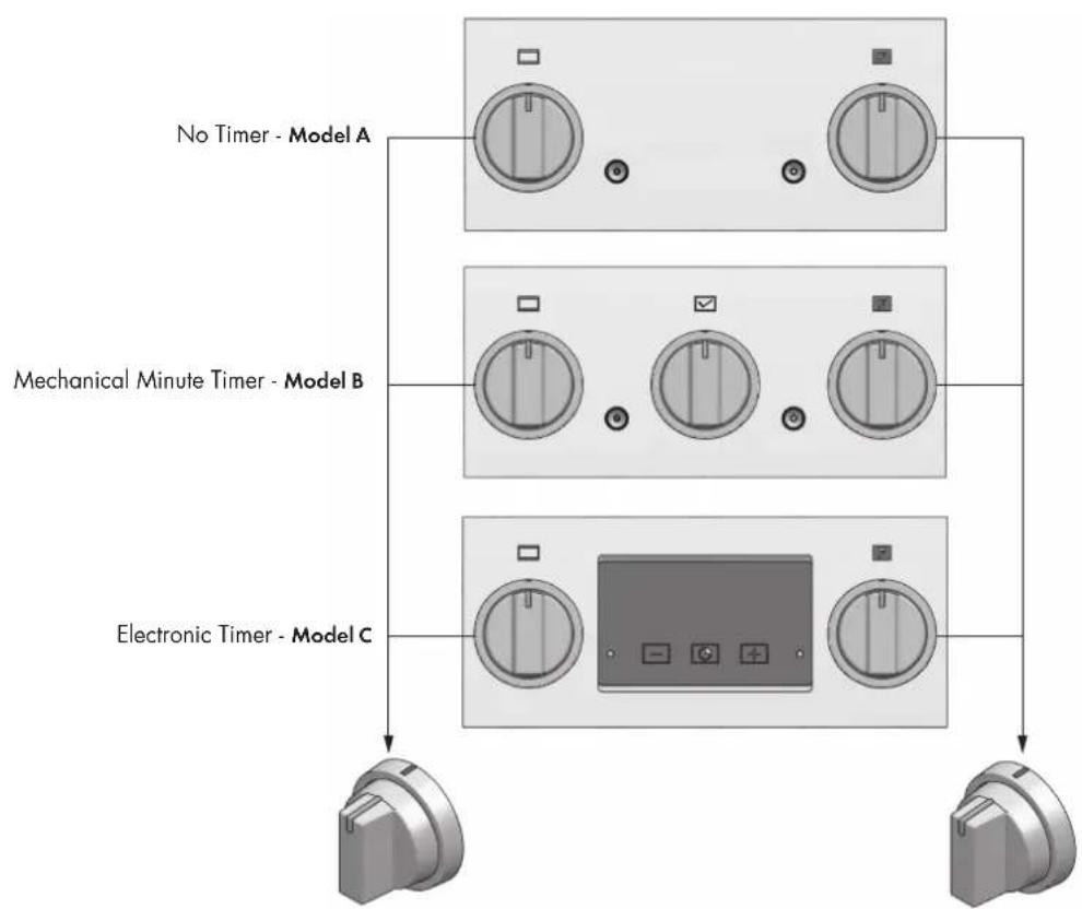
CONTROL PANEL


Control
Model A: No Timer
Model B: Mechanical Minute Timer
Model C: Electronic Timer
Signal lamps
Left: Gas oven indicator light
Right: Electrical indicator light
Knobs
Function selector, with two functions + OFF position.
- Light
- Oven fan
Thermostat with two functions + OFF position.
- Counterclockwise: Oven burner + temperature regulation.
- Clockwise: Grill Burner
EN 12 - General Oven Information
Cooling Fan
The fan is situated at the top of the oven and creates a circulation of cooling air inside the cabinet which comes out of the slits under the instrument panel of the oven. It comes on whenever the oven is turned on, for whatever function.
If it fails to come on call the nearest service centre.
Convection Fan
The convection fan operates during any convection mode. When the oven is operating in the convection mode, the fan will turn off automatically when the door is opened.
Oven Light
The oven light is normally off and will turn on when the door is opened. The Function Selector knob can be used to keep the oven light on constantly. When the Function Selector knob is turned to the convection fan position, the interior light remains on constantly. The light cannot be turned off while the convection mode is selected.
Rear Oven Vent
The warm air from the oven is exhausted through vents located at the rear of the cooktop. Do not allow the airflow from the rear vents to be obstructed by cookware or towels.
Prior to First Use
To ensure all residual oil from the manufacturing process has been removed, each oven must go through the following procedure.
- Clean oven thoroughly with hot water and a mild detergent. Rinse and dry with a soft cloth.
- Turn on ventilation. Some smoke and odor is normal.
- Set oven temperature to 250^ (120^) and allow oven to heat for 1 hour.
- Set oven temperature to 500^ (260^) and allow oven to heat for an additional hour.
- Turn oven off and allow it to cool with the door closed.
Preheating the Oven
- Preheat the oven when using the Bake, Convection Bake and Broil modes.
- Selecting a higher temperature does not shorten the preheat time.
- Preheating is necessary for good results when baking cakes, cookies, pastry and breads.
- Preheating will help to sear roasts and seal in meat juices.
- Place oven racks in their proper position before preheating.
- There is no light or chime indication that the oven has reached the set temperature.
| Estimated Preheating Time for Range 36" | |
| °F°C MIN:SEC | |
| 250 ~ 120 2:30 | |
| 325 ~ 165 4:00 | |
| 375 ~ 190 5:00 | |
| 425 ~ 220 7:00 | |
| 475 ~ 245 9:00 | |
| 550 ~ 290 11:30 | |
| Estimated Preheating Time for Range 30" | |
| °F°C MIN:SEC | |
| 250 ~ 120 2:30 | |
| 325 ~ 165 3:30 | |
| 375 ~ 190 4:30 | |
| 425 ~ 220 5:30 | |
| 475 ~ 245 7:00 | |
| 550 ~ 290 11:00 | |
Operational Suggestions
- Do not set pans on the open oven door.
- Use the interior oven lights to view the food through the oven door window rather than opening the door frequently.
- You can set the minute timer using the preheat timing chart above to let you know when the oven is preheated to the set temperature.
- You can set the minute timer using the preheat timing chart above to let you know when the oven is preheated to the set temperature.
Utensils
Glass baking dishes absorb heat. Reduce oven temperature 25^ (15^) when baking in glass.
- Use pans that give the desired browning. The type of finish on the pan will help determine the amount of browning that will occur.
- Shiny, smooth metal or light non-stick / anodized pans reflect heat, resulting in lighter, more delicate browning. Cakes and cookies require this type of cookware.
- Dark, rough or dull pans will absorb heat resulting in a browner, crisper crust. Use this type for pies.
- For brown, crisp crusts, use dark non-stick / anodized or dark, dull metal utensils or glass bake ware. Insulated baking pans may increase the length of cooking time.
- Do not cook with the empty broiler pan in the oven, as this could change cooking performance. Store the broil pan outside of the oven.
Oven Condensation and Temperature
It is normal for a certain amount of moisture to evaporate from the food during any cooking process. The amount depends on the moisture content of the food. The moisture may condense on any surface cooler than the inside of the oven, such as the control panel.
High Altitude Baking
- When cooking at high altitude, recipes and cooking time will vary from the standard.
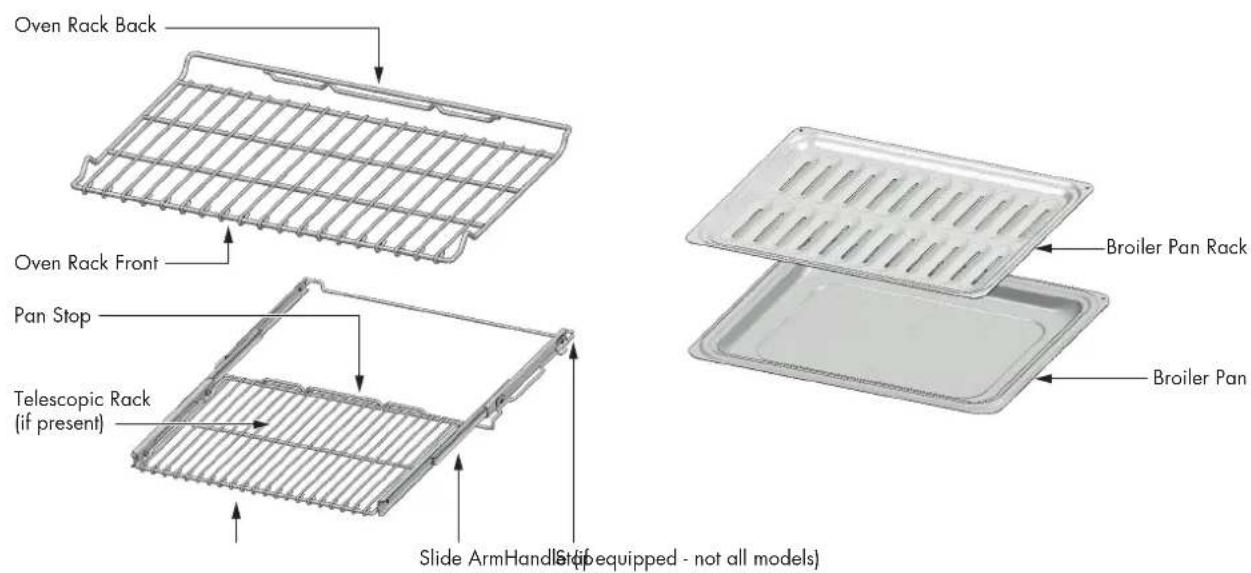
Oven Racks
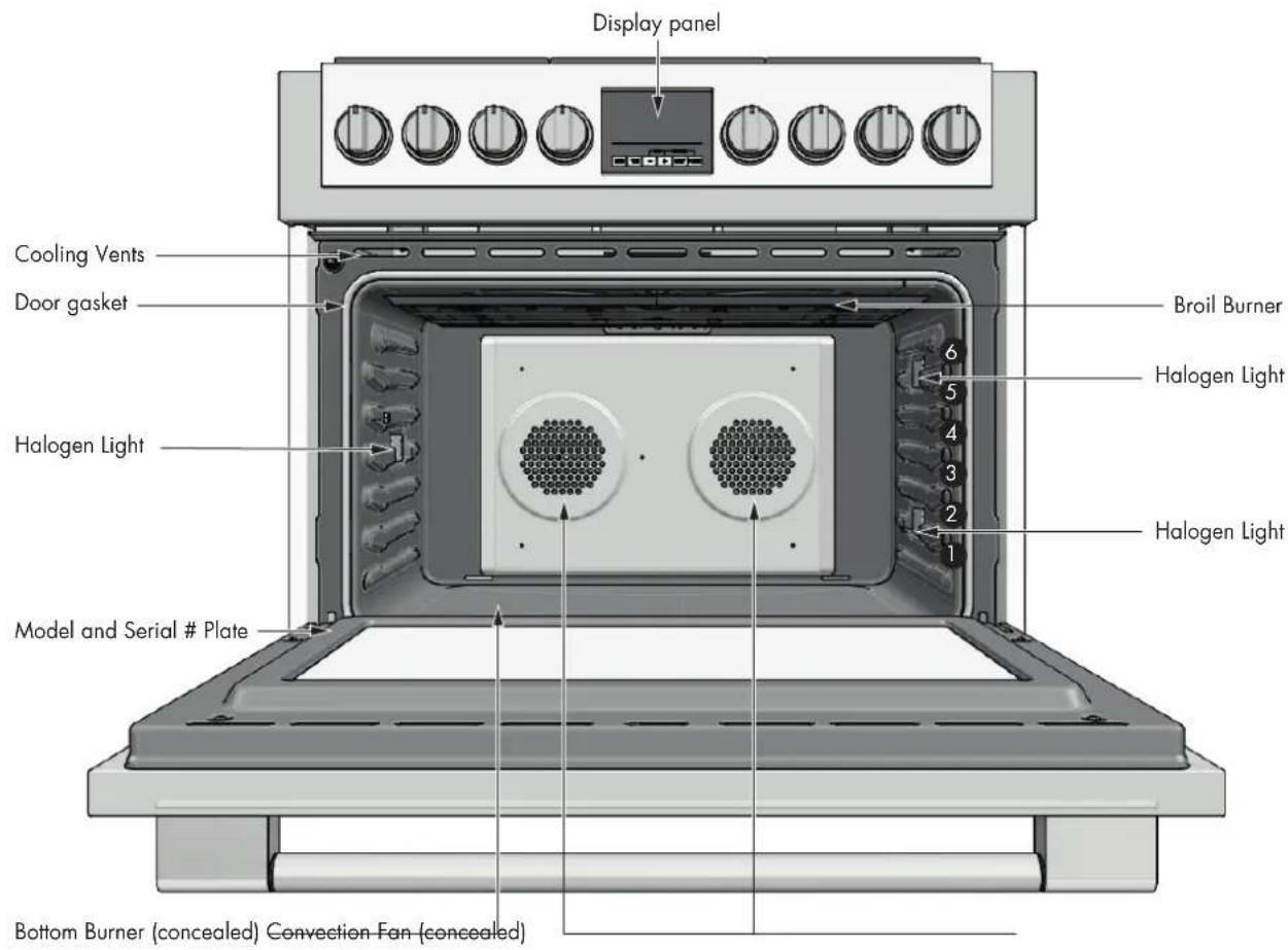
- The oven has rack guides at six levels as shown in the illustration on Page 2.
- Rack positions are numbered from the bottom rack guide (#1) to the top (#6).
Each level guide consists of paired supports formed in the walls on each side of the oven cavity.
Always be sure to position the oven racks before turning on the oven. Make sure that the racks are level and secure once they are in position.
Please refer to illustration on Page 2 if there is any question as to which side is the front of the rack.
- The racks are designed to stop when pulled forward to their limit.

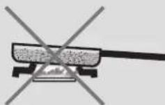
CAUTION
Never use aluminum foil to cover the oven racks or to line the oven. It can cause damage to the oven liner if heat is trapped under the foil.

CAUTION
Make sure you do not force it to avoid damage to the enamel.
To remove oven rack from the oven:
- Pull rack forward
EN 13 - General Oven Tips
- Lift rock up at front and then remove it
To replace an oven rack:
- Place rear of rack between rack level guides
- While lifting front of rack, slide rack in all the way while lowering the front
Oven Telescopic Racks
- The telescopic rack allows for easier access to cooking foods for repetitive activities such as basting. It extends beyond the standard flat rack bringing the food closer to the user.

CAUTION
When the rack is outside of the oven, slide arms do not lock. They could unexpectedly extend if the rack is carried incorrectly.
Extending slide arms could cause injury.
Rack should only be held or carried by grasping the sides.
NOTE: Always remove the extendable rack before self-cleaning the oven.

CAUTION
To avoid burns, pull rack all the way out and lift pan above handle when transferring food to and from oven.
Please refer to illustration on Page 2 if there is any question as to which side is the front of the rack.
To remove extendable rack from the oven:
- Lift of rack slightly and push it towards the back of the oven until the stop releases.
- Raise back of rack until frame and stop clear rack guide
- Pull rack down and out
To replace an extendable rack:
- Grasp rack firmly on both sides. Place rack (including frame) above desired rack guide
- Push all the way in until the back of the rack drops into place
- Pull both sections forward until stops activate. Rack should be straight and flat, not crooked
Mechanical Minute Timer
The minute minder can be set to a maximum time of 60 minutes; it emits an alarm tone when the set time period has elapsed. The minute timer operates independently of the oven.
On models equipped with a mechanical timer rather than an electronic timer, the timer knob must first be turned clockwise to the 60 minute position and then turned counter-clockwise to the desired time setting. When the set time has elapsed, the alarm will sound.
The alarm tone will stop automatically after a certain period.
Timer Touch Control
Setting the clock
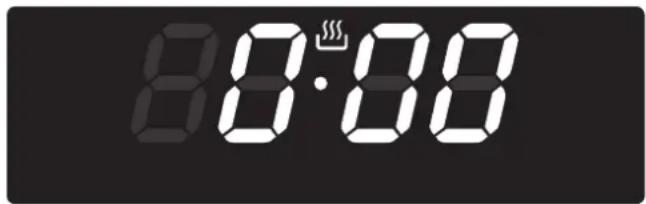
"Auto" and "0:00" will start flashing when the unit is switched on for the first time. To set the clock, press the central button for about 3 seconds. When pears, press + or - to set the correct time.
Note: only 24 hrs setting available.
Wait until a beep tells you that the clock has been set.
To set the time at a later stage, press + and together for 3 seconds and then adjust the clock as described above.
Minute counter
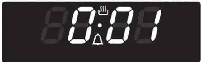
As this minute counter does not control the oven, when it finishes counting the oven will continue to work.
To set, press the central button for 3 seconds until A pears. Press + and - to set the required time.
To set the minute counter at a later stage, press the central button for 3 seconds and adjust as described above.
The minute counter beeps when it finishes counting.
To disable it, press any button.
Adjusting beep volume
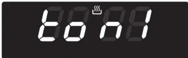
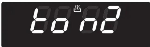
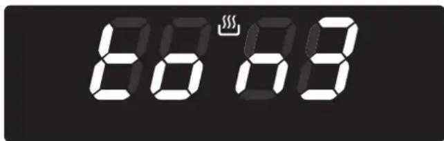
To adjust beep volume, press + and together. Then press the central button and wait for "ton1" (high volume) to flash. Press to select "ton2" (medium volume) or "ton3" (low volume).
Press the central button to set the selected volume.
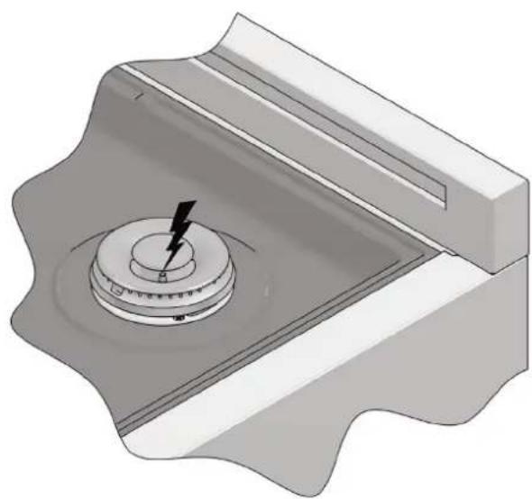
Lighting your gas oven
To turn on the gas oven, push in the thermostat knob to activate the spark generator. Then, keeping the knob pushed in, turn counter-clockwise for the Bake mode (past the 275^ or 295^ position depending on the model) or clockwise for Broil Mode and hold in for a few seconds. When starting the gas oven, the ignitor continuing to fire for a few seconds after releasing the knob is not an indication that the burner is not lit.
The ignitor will continue to spark until the flame heats up the temperature sensor which will then allow continuous flow of gas through the safety valve.
You can tell that the oven is lit by checking for flame visually:
- through the small holes situated in the base of the oven (Bake Mode)
- on the broiler mounted on the ceiling of the oven cavity (Broil Mode).
Bake Temperature Control
The temperature control knob serves to set the desired oven temperature and is equipped with a safety valve. When the oven is in operation the ON light is illuminated.
To turn on the bottom burner, push the temperature control knob and turn it counterclockwise to the desired temperature.
The minimum position corresponds to an oven temperature of:
$$ 3 6 ^ {\prime \prime} = 2 7 5 ^ {\circ} F (1 3 5 ^ {\circ} C) $$
The control knob has stop in the minimum position.
The maximum position corresponds to an oven temperature of 36^ = 550^ (290°C)
and is obtained when the knob is turned fully counterclockwise.

WARNING
If, when turning the thermostat knob and it does not appear to function properly, turn off the gas supply to the oven and call the nearest service center.
Broil
To turn on the broiler, press and turn the knob clockwise to the broil position.

WARNING
When using the broiler accessible parts may get hot, keep children at a safe distance.
Convection Mode Benefits
The convection fan function turned on together with the strong heat coming from the bottom burner makes it possible to cook foods more evenly and delicately than with the bottom burner alone.
Cooking is faster than in a traditional oven. The system is suitable for cooking foods of different types (fish, meat etc) on a number of levels.
Pre-heating is not necessary when using convection modes but is still recommended for baking.
With this convection cooking method, you can operate the oven in the normal way and follow the instructions in recipe books.
The food to be cooked should preferably be placed on the middle shelf of the oven.

WARNING
Prolonged use of gas appliances produces heat and humidity in the kitchen. This may make additional ventilation such as opening a window or more efficient ventilation necessary, for example by boosting the level of mechanical ventilation where present (suction hood).
MAIN COURSE TEMPERATURE ^ (°C) COOKING TIME (min) PREHEAT
| Genoese Sponge (Swiss Roll) | 410 (210) 15 - 20 | Yes | |
| Short Pastry (Biscuits) | 390 (200) 10 - 12 | Yes | |
| Dough With Raising Agent (Schiacciata) | 390 (200) 25 - 30 | Yes | |
| Sponge Cake (Small Paper Pastry Cases) | 375 (190) 20 - 25 | Yes | |
| Leavened Dough (Strudel) | 355 (180) 40 - 50 | Yes | |
| Puff Pastry (Tartlets) | 375 (190) 20 - 30 | Yes | |
| Soufflé | 355 (180) 35 - 40 | Yes | |
| Sachertorte | 355 (180) 55 - 60 | Yes | |
| Fruit Pie | 320 (160) 160 - 180 | Yes | |
| Choux Pastry | 390 (200) 35 - 40 | Yes | |
| Roast Beef (Approx. 1.5 Kg) | 390 (200) 90 - 120 | Yes | |
| Pizza | 390 (200) 20 - 25 | Yes | |
| Baked Fish | 355 (180) 50 - 60 | Yes | |
| Baked Vegetables | 340 (170) 30 - 40 | Yes | |
| Poultry | 375 - 390 (190 - 200) | 60 - 70 | Yes |
Guideline values for cooking with the broiler
| MAIN COURSE COOKING TIME (min) PREHEAT | ||
| Steaks | 10 - 15 | - |
| Cutlet | 15 - 25 | - |
With either Bake or Convection Bake, poor results can occur for many reasons other than a malfunction of the oven. Check the chart below for causes of the most common problems. Since the size, shape and material of baking utensils directly affect the baking results, the best solution may be to replace old baking utensils that have darkened and warped with age and use.
| BAKING PROBLEM CAUSE | |
| Food browns unevenly | - Oven not preheated - Aluminum foil on oven rack or oven bottom - Baking utensil too large for recipe - Pans touching each other or oven walls |
| Food too brown on bottom | - Oven not preheated - Using glass, dull or darkened metal pans - Incorrect rack position - Pans touching each other or oven walls |
| Food is dry or has shrunk excessively | - Oven temperature too high - Baking time too long - Oven door opened frequently - Pan size too large |
| Food is baking or roasting too slowly | - Oven temperature too low - Oven not preheated - Oven door opened frequently - Tightly sealed with aluminum foil - Pan size too small |
| Pie crusts do not brown on bottom or have soggy crust | - Baking time not long enough - Using shiny steel pans - Incorrect rack position - Oven temperature is too low |
| Cakes pale, flat and may not be done inside | - Oven temperature too low - Incorrect baking time - Cake tested too soon - Oven door opened too often - Pan size may be too large |
| Cakes high in middle with crack on top | - Baking temperature too high - Baking time too long - Pans touching each other or oven walls - Incorrect rack position - Pan size too small |
| Pie crust edges too brown | - Oven temperature too high - Edges of crust too thin |

ATTENTION
- Make sure oven is cool and power to the oven has been turned off before removing the door. Failure to do so could result in electrical shock or burns.
- The oven door is heavy and fragile. Use both hands to remove the oven door. The door front is glass.
- Handle carefully to avoid breakage.
- Grasp only the sides of the oven door. Do not grasp the handle as it may swing in your hand and cause damage or injury.
- Failure to grasp the oven door firmly and properly could result in personal injury or product damage.
To Remove Door
- Open the door completely.
- Flip the hinge security clip on each hinge towards you (1).
- Hold the door firmly on both sides using both hands and close the door.
- Hold firmly; the door is heavy.
- Place the door in a convenient location.
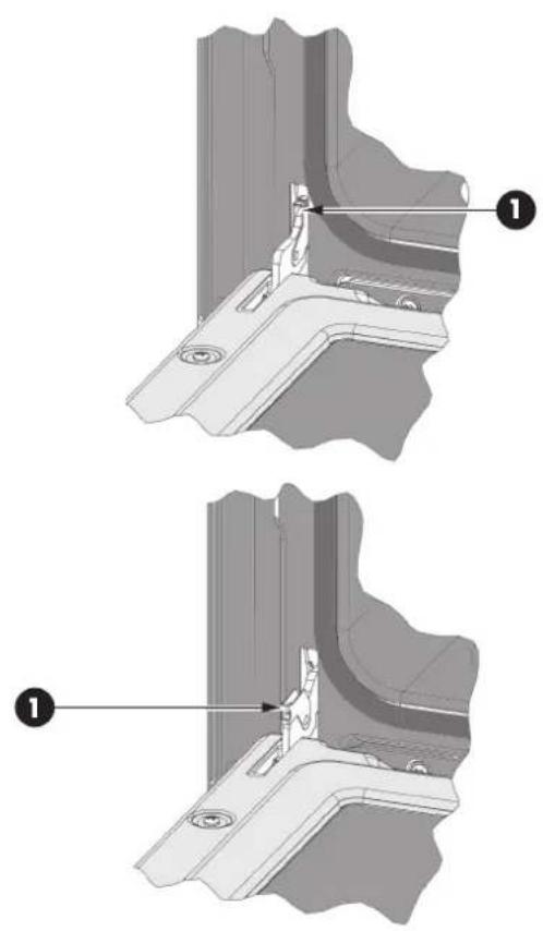
TO REMOVE THE DOOR
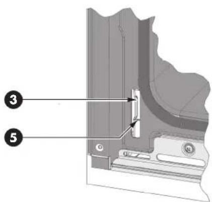
To Replace Door
- Insert the upper arms (2) of both hinges into the slots (3). The recesses (4) must hook on the lips (5).
- Move the hinge security clips (1) back into position.
- Close and open the door slowly to assure that it is correctly and securely in place.
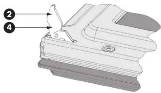
TO REPLACE DOOR
EN 19 - Replacing an Oven Light
Each oven is equipped with three halogen lights located in the lateral walls of the oven.
- The lights are switched on when the door is opened or when the oven is in a cooking cycle.
Each light assembly consists of a removable lens, a light bulb as well as a light socket housing that is fixed in place. See figure on this page.
Light bulb replacement is considered to be a routine maintenance item.
To Replace a Light Bulb
- Read WARNING on this page.
- Turn off power at the main power supply (fuse or breaker box).
- Remove the lens between screw and glass using a screw driver.
- Remove the light bulb from its socket by pulling it.
- Replace the bulb with a new one. Avoid touching the bulb with fingers, as oils from hands can damage the bulb when it becomes hot.
- The bulb is halogen: use one with the same type checking Voltage and Wattage.
- Place the lens back on.
- Replace the rack supports if provided is provided with the oven model.
Turn power back on at the main power supply (fuse or breaker box).

WARNING
- Make sure the oven and lights are cool and power to the oven has been turned off before replacing the light bulb(s). Failure to do so could result in electrical shock or burns.
The lenses must be in place when using the oven. - The lenses serve to protect the light bulb from breaking.
- The lenses are made of glass. Handle carefully to avoid breakage. Broken glass could cause an injury.
OVEN LIGHT
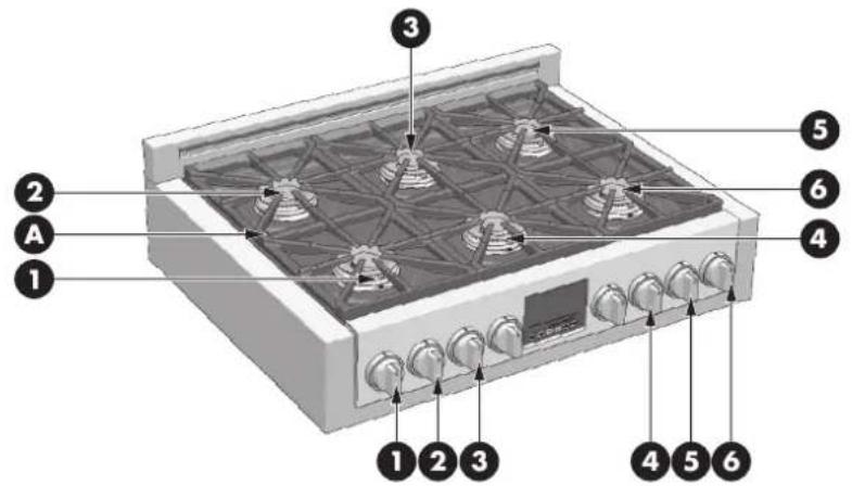
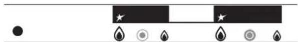
COOKTOP 36"
A-Grates
| BURNER OUTPUT RATINGS: BTU/HR MODEL 36" | NG (Natural) LP (Propane) | |
| 1 DOUBLE CROWNS Burner & knob) | 15350 (Btu/h) - 4500W/1200 (Btu/h) 350W | 15350 (Btu/h) - 4500W/1200 (Btu/h) 350W |
| 2 DOUBLE CROWNS Burner & knob) | 15350 (Btu/h) - 4500W/1200 (Btu/h) 350W | 15350 (Btu/h) - 4500W/1200 (Btu/h) 350W |
| 3 DOUBLE CROWNS Burner & knob) | 15350 (Btu/h) - 4500W/1200 (Btu/h) 350W | 15350 (Btu/h) - 4500W/1200 (Btu/h) 350W |
| 4 DOUBLE CROWNS Burner & knob) | 15350 (Btu/h) - 4500W/1200 (Btu/h) 350W | 15350 (Btu/h) - 4500W/1200 (Btu/h) 350W |
| 5 DOUBLE CROWNS Burner & knob) | 15350 (Btu/h) - 4500W/1200 (Btu/h) 350W | 15350 (Btu/h) - 4500W/1200 (Btu/h) 350W |
| 6 DOUBLE CROWNS Burner & knob) | 15350 (Btu/h) - 4500W/1200 (Btu/h) 350W | 15350 (Btu/h) - 4500W/1200 (Btu/h) 350W |
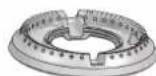
BURNER
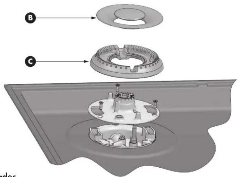
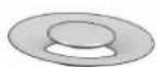
B-Burner Cap
C-Burner Gas Spreader
EN 21 - Gas Cooktop Operation
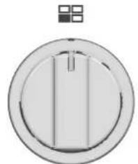
Gas Control Knob Setting
Electric gas ignition
The gas burner use an electric ignition device located near each burner that ensures burner ignition.
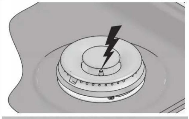
ELECTRIC IGNITION
Models with automatic ignition
The electronic auto ignition, lights the surface burner when the corresponding control knob is turned at any valve rotation allows admits sufficient gas flow to support a flame.
To set:
- Push and turn a knob counter clockwise to any setting, all spark plugs will generate a clicking sound (spark), however only the burner with the control knob adjusted to the range will produce a flame.

WARNING
- Do not operate a burner using empty cookware or without cookware on the grate.
- Do not touch the burner when the ignitors are clicking (sparking).
- Do not let the burner flame extend beyond the edge of the pan.
- Turn off all controls when not cooking.
Failure to follow these instruction can result in personal injury or fire.
Gas burners
The gas burners design of these cooktop models, allow a pleasing option for cooking where size, power and simmering are a primary concern.
Burners with two flame rings
This special burner has two separate flame rings to provide a complete heat regulation from high power to simmering.
To set:
- Push and turn the knob counter clockwise withing the main - orange, when the burner is turned on, the main flame and the Simmer flame will both ignite and remain on.
- Set desired temperature within the main - range.
Simmer setting
Continue turning the knob counterclockwise to the 'SIMMER' range. The outer flame ring will go out and temperature adjustment can be made using the inner flame ring only.
Turning off the burner
Turn the knob clockwise as far as it will go to the off position.
Ensure flame extinguishes fully.
KNOB BURNER
The Burner Flames
Turn each burner on. Flames should be blue in color with no trace of yellow. The burner flames should not flutter or blow away from the burner. The inner cone of the flame should be between 1/2'' and 3/4'' long.
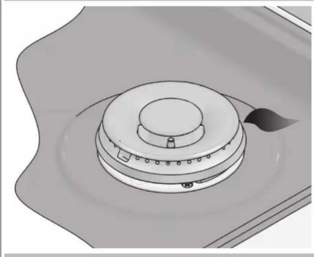
Super Sealed Surface Burners

IMPORTANT
Do not obstruct the flow of combustion and ventilation air around the burner grate edges.
Burner cap and gas spreader
Always keep the burner cap and gas spreader in place when using a surface burner. A clean burner cap and spreader will help prevent poor ignition and uneven flames. Always clean the parts after a spillover and routinely remove and clean according to the "General Cleaning" section.
Burner base and injector
Gas must flow freely throughout the injector orifice to light properly. Keep this area free of soil and do not allow spills, food, cleaning agents or any other material to enter the injector orifice opening.
Protect it during cleaning.
ELECTRIC IGNITION
Be sure when lighting the burner:
Gas spreader is seated correctly and pin is properly aligned with burner base slot.
- Cap is seated correctly and pin is properly aligned with gas spreader slot.
Burner ports
Check burner flames occasionally. A good flame is blue in color, not yellow.
Keep this area free of soil and do not allow spills, food,
cleaning agents or any other material to enter the burner ports.
To Clean gas burner:

IMPORTANT
Before cleaning, make sure all controls are off and the cooktop is cool.
- Remove the burner cap from the burner base and clean according to cleaning section.
- Remove the burner spreader.
Clean the gas tube opening and burner port according to cleaning section.
- Clean the burner base with a damp cloth (keep the gas injector area free of cleaning agents and any other material from entering the injector orifice).
-
Replace the burner spreader and cap, making sure the alignment pins are properly aligned with the slots.
-
Turn on the burner.
If the burner does not light, check cap and spreader alignment. If the burner still does not light, do not service the gas burner yourself.
Contact a trained repair specialist.
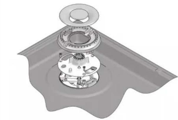
EXPLODED VIEW OF BURNER
IMPORTANT: Never leave empty cookware on a hot surface cooking area, element or surface burner.
Ideal cookware should have a flat bottom, straight sides, a well fitting lid and the material should be of medium-to-heavy thickness. Rough finishes may scratch the cooktop.
Aluminium and copper may be used as a core or base in cookware. However, when used as a base it can leave permanent marks on the cooktop or grates.
Cookware material is a factor in how quickly and evenly heat is transferred, which affects cooking results. A nonstick finish has the same characteristics as its base material.
For example, aluminium cookware with a non-stick finish will take on the properties of aluminium.
Use the following chart as a guide for cookware material characteristics.
Cookware Characteristics
Aluminum:
Heats quickly and evenly.
Suitable for all types of cooking. Medium or heavy thickness is best for most cooking tasks.
Cast Iron:
Heats slowly and evenly.
Good for browning and frying. Maintains heat for slow cooking.
Ceramic or Ceramic glass:
Follow manufacturer's instructions.
Heats slowly, but unevenly. Ideal results on low to medium heat settings.
Copper:
Heats very quickly and evenly.
Earthenware:
Follow manufacturer's instructions.
Use on low heat settings.
Porcelain enamel on steel or cast Iron:
See stainless steel or cast iron.
Stainless steel:
Heats quickly, but unevenly. A core or base of aluminium or copper on stainless steel provides even heating.
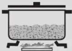
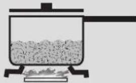
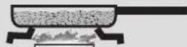
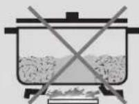
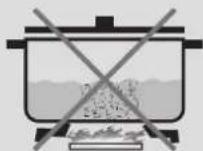
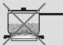
Match Pan Diameter to Flame Size
The flame should be the same size as the bottom of the pan or smaller. Do not use small pans with high flame settings as the flames can lick up the sides of the pan. Oversize pans that span two burners are placed front to rear, not side to side.
Use Balanced Pans
Pans must sit level on the cooktop grate without rocking. Center pan over burner.
Use a Lid That Fits Properly
A well-fitting lid helps shorten the cooking time. Flat, heavy bottom pans provide even heat and stability.

WARNING
BALANCED PAN
CONCAVE (HOLLOW)
CONVEX (ROUNDED)
FLAMETOOLARGEFORPANSIZE
USE LIDS THAT FIT PROPERLY
UNBALANCED PAN
How to Use the Oven Cleaning Chart
- Locate the number of the part to be cleaned in the illustration on this page.
-
Find the part name in the chart.
-
Use the cleaning method in the left column if the oven has a colored enamel finish.
-
Use the cleaning method in the right column if the oven is stainless steel.
-
Match the letter with the cleaning method on following page.
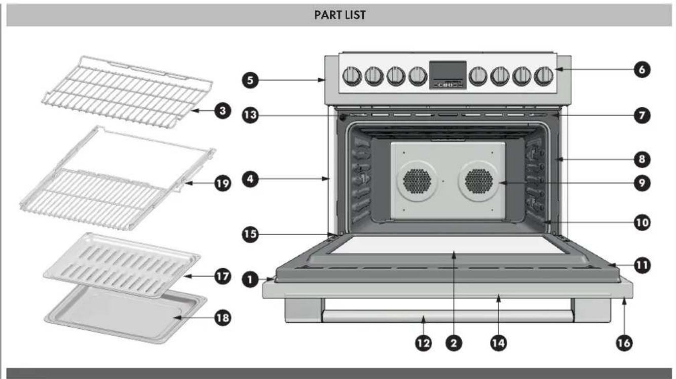
| Cleaning Chart | ||||||
| Part | Cleaning Method | Part Enamelled Stainless Steel Enamelled Stainless Steel | Cleaning Method | |||
| 1 | Door Frame | D | G | 11 | Interior Oven Door | E |
| 2 | Interior Door Windows | F | F | 12 | Door Handle | G |
| 3 | Removable Oven Racks | A or E | A or E | 13 | Door Cooling Vent | E |
| 4 | Slide Trim | G | G | 14 | Door Front | C&D |
| 5 | Control Panel Trim | G | G | 15 | Oven Trim | D |
| 6 | Control Panel | D | G | 16 | End Caps | D |
| 7 | Oven Cooling Vents | D | D | 17 | Broil Pan Rack | E |
| 8 | Oven Front Frame | E | E | 18 | Broil pan Bottom | E |
| 9 | Oven Cavity | E | E | 19 | Extendable rack | A |
| 10 | Mesh Gasket | B B | ||||
EN 25 - Oven Finishes / Cleaning Methods
The entire oven can be safely cleaned with a soapy sponge, rinsed and dried. If stubborn soil remains, follow the recommended cleaning methods below.
Always use the mildest cleaner that will do the job.
- Rub metal finishes in the direction of the grain.
- Use clean, soft cloths, sponges or paper towels.
- Rinse thoroughly with a minimum of water so it does not drip into door slots.
- Dry to avoid water marks.
The cleaners listed below indicate types of products to use and are not being endorsed. Use all products according to package directions.
| Part Cleaning Method | |
| A Chrome Plated | Wash with hot sudsy water. Rinse thoroughly and dry. Or, gently rub with Soft Scrub®, Bon-Ami®, Comet®, Ajax®, Brillo® or S.O.S® pads as directed. Easy Off® or Dow® Oven Cleaners (cold oven formula) can be used, but may cause darkening and discoloration. Racks may be cleaned in the oven during the self-clean mode. However, chromed racks will lose their shiny finish and permanently change to a metallic gray. |
| B Fiberglass Knit | DO NOT HAND CLEAN GASKET. |
| C Glass | Spray Windex® or Glass Plus® onto a cloth first then wipe to clean. Use Fantastik® or Formula 409® to remove grease spatters. |
| D Painted | Clean with hot sudsy water or apply Fantastik® or Formula 409® first to a clean sponge or paper towel and wipe clean. Avoid using powdered cleansers and steel wool pads. |
| E Porcelain | Immediately wipe up acidic spills like fruit juice, milk and tomatoes with a dry towel. Do not use a moistened sponge/towel on hot porcelain. When cool, clean with hot sudsy water or apply Bon-Ami® or Soft Scrub® to a damp sponge. Rinse and dry. For stubborn stains, gently use Brillo® or S.O.S.® pads. It is normal for porcelain to craze (fine lines) with age due to exposure from heat and food soil. |
| F Reflective Glass | Clean with hot sudsy water and sponge or plastic scrubber. Rub stubborn stains with vinegar, Windex®, ammonia or Bon-Ami®. DO NOT USE HARSH ABRASIVES. |
| G Stainless | Always wipe or rub with grain. Clean with a soapy sponge then rinse and dry. Or, wipe with Fantastik® or Formula 409® sprayed onto a paper towel. Protect and polish with Stainless Steel Magic® and a soft cloth. Remove water spots with a cloth dampened with white vinegar. Use Zud®, Cameo®, Bar Keeper's Friend® or RevereWare Stainless Steel Cleaner®, to remove heat discoloration. |
The entire Cooktop can be safely cleaned by wiping with a soapy sponge, then rinsing and drying. If stubborn soil remains, follow the recommended cleaning methods below.

ATTENTION
- Before cleaning, be certain the burners are turned off and the grates are cool.
Always use the mildest cleaner that will do the job. Use clean, soft cloths, sponges or paper towels. - Rub stainless steel finishes in the direction of the grain. Wipe area dry to avoid water marks.
- Do not clean removable cooktop parts in any selfcleaning oven.
- After cleaning, place all parts in their proper positions before using cooktop.
The cleaners recommended below and on the following page indicate cleaner types and do not constitute an endorsement of a particular brand.
Use all products according to package directions.
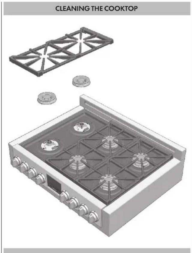
Cooktop Part / Material Suggested Cleaners
| Parts and materials Suggested cleaners Suggestions/Reminders | ||
| Burner base(Cast aluminium) | Damp cloth. Keep the gas injector area free | of cleaningagents and any other material from entering the injector orifice. |
| Gas spreader(Cast aluminium) | Detergent and hot water; rinse and dry.Stiff nylon bristle-toothbrush to clean port openings.Abrasive cleansers: Revere ware® metal polish. Following package direction Use Brillò® or S.O.S.® pads.Rinse and dry. | Rub lightly, in a circular motion.Aluminium cleaners may dull the surface.To clean port opening, use a tooth brush or straightened paper clip. Take care not to damage / augment the shape of the ports. |
| Gas spreader(Brass) | Wash them in hot soapy water, rinse, and dry.Use a stiff nylon brush or straight-ended paper clip to clear the notches of a flame spreader. | Rub lightly, in a circular motion.Brass cleaners may dull the surface.To clean port opening, use a tooth brush or straightened paper clip. |
| Burner cap and grate(Porcelain enamel on cast iron) | Non abrasive cleaners: Hot water and detergent, Fantastic, Formula 409. Rinse and dry immediately.Mild abrasive cleaners: Bon Ami® and Soft Scrub®.Abrasive cleaners for stubborn stains: soap-filled steel wool pad. | The grates are heavy; use care when lifting. Place on a protected surface.Blisters/crazing/chips are common due to the extreme temperatures on grate fingers and rapid temperature changes.Acidic and sugar-laden spills deteriorate the enamel. Remove soil immediately.Abrasive cleaners, used too vigorously or too often, can eventually mar the enamel. |
| Exterior finish (Porcelain enamel) | Hot sudsy water: rinse and dry thoroughly. Non abrasive cleansers: Ammonia, Fantastic®, Formula 409®. Mild abrasive cleansers: Bon Ami®, Ajax®, Comet®. Liquid cleaners: Kleen King®, Soft Scrub® | Acidic and sugar-laden spills deteriorate the porcelain enamel. Remove soil immediately. Do not use wet sponge or towel on hot porcelain. Always apply minimal pressure with abrasive cleaners. |
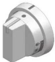
| Control knobs (Stainless Steel) | Hot sudsy water: rinse and dry immediately. If necessary, remove knobs (lift straight up). | Do not soak knobs. Do not use abrasive scrubbers or cleansers. Do not force knobs onto valve shaft. Pull knobs straight away from control panel to remove. When replacing knobs, make sure knobs are in the OFF position. Do not remove seats under knobs. |
| Exterior finish (Stainless Steel) | Nonabrasive cleaners: Hot water and detergent. Fantastic®, Formula 409®. Rinse and dry immediately. Cleaner polish: Stainless Steel Magic® to protect the finish from staining and pitting; enhances appearance. Hard water spots: Household white vinegar. Mild Abrasive Cleaners: Kleen King® stainless steel liquid cleaner, Cameo® aluminum & stainless steel cleaner, Bon Ami®. Heat discoloration: Bar Keepers Friend®. | Stainless steel resists most food stains and pit marks provided the surface is kept clean and protected. Never allow food stains or salt to remain on stainless steel for any length of time. Rub lightly in the direction of polish lines. Chlorine or chlorine compounds in some cleaners are corrosive to stainless steel. Check ingredients on label before using. Always apply minimal pressure with abrasive cleaners especially on graphics. |
| Igniters (Ceramic) | Carefully wipe with a cotton swab dampened with water, ammonia or Formula 409®. Gently scrape soil off with a toothpick. | Avoid excess water on the igniter. A damp igniter will prevent burner from lighting. Remove any lint that may remain after cleaning. |
Before contacting service, check the following to avoid unnecessary service charges.
| Oven Problem Problem Solving Steps | |
| The oven display stays OFF Turn off | power at the main power supply (fuse or breaker box). Turn breaker back on. If condition persists, call an authorized service. |
| Cooling fan continues to run after oven is turned off | The fan turns off automatically when the electronic components have cooled sufficiently. |
| Oven temperature is too hot or too cold | The oven thermostat needs adjustment. See Calibrating Oven Temperature, Page 28. |
| Oven light is not working properly | Replace or reinsert the light bulb if loose or defective. See Page 32. Avoid touching the bulb glass with bare fingers as finger oil may cause bulbs to burn out prematurely. |
| Oven light stays on Check for obstruction | In case of an oven door. Check to see if hinge is bent or door switch broken. |
| Cannot remove lens cover on light | There may be a soil build-up around the lens cover. Wipe lens cover area with a clean dry towel prior to attempting to remove the lens cover. |
| Excessive moisture | When using Bake mode, preheat the oven first. Convection Bake and Convection Roast will eliminate any moisture in oven (this is one of the advantages of convection). |
| Porcelain chips | When oven racks are removed and replaced, always tilt racks upward and do not force them to avoid chipping the porcelain. |
| Ignition will not operate | |
| Is the power supply cord unplugged? | Plug into a grounded 3 prong outlet. |
| Has a household fuse been blown or has the circuit breaker been tripped? | Replace the fuse or reset the circuit. |
| Surface burners will not operate | |
| Is this the first time the surface burners have been used? | Turn on any one of the surface burner knobs to release air from the gas lines. |
| Is the control knob set correctly? Push in knob before turning to a setting. | |
| Are the burner ports clogged? See "Super Sealed Surface Burners" section. | |
| Surface burner flames are uneven yellow and/or noisy | |
| Are the burner ports clogged? See "Super Sealed Surface Burners" section. | |
| Are the burner caps positioned properly? | See "Super Sealed Surface Burners" section. |
| Is propane gas being used? The appliance may have been converted improperly. Contact a service technician. | |
| Surface burner makes popping noises | |
| Is the burner wet? Let it dry. | |
| Is the cap and gas spreader positioned correctly? | Make sure the alignment pins are properly aligned see "Super Sealed Surface Burners" section. |
| Excessive heat around cookware on cooktop | |
| Is the cookware the proper size? | Use cookware about the same size as the surface cooking area, element or surface burner. Cookware should not extend more than 1 in (2.5 cm) outside the cooking area. |
| Cooktop cooking results not what expected | |
| Is the proper cookware being used? | See "Cookware" section. |
| Is the control knob set to the proper heat level? | See "Setting the Control Knobs" section. |
EN 28 - Assistance or Service
Before contacting service, please check "Troubleshooting." It may save you the cost of a service call.
If you still need help, follow the instructions below. When calling, please know the purchase date and the complete model and serial number of your appliance. This information will help us to better respond to your request.
Service Data Record
For authorized service or parts information see WARRANTY.
For serial tag location see Page 2. Now is a good time to write this information in the space provided below.
Keep your invoice for warranty validation.
Service Data Record
Model Number
Serial Number
Date of Installation or Occupancy
TABLE DES MATIÈRES PAGE
Pourretirerlaporte 31
FOUR 17000 Btu/h (5000W) 17000 Btu/h (5000W)
| CONTENU DE VOTRE PACK DE CUISSON | ||||
| QTÉ DESCRIPTION QTÉ DESCRIPTION | ||||
| 1 CUISINIÈRE 1 PIED AVEC COLIER | ||||
| 1 | DOSSERET 3" TROIS VIS DE FIXATION | 1 | QUATRE VIS DE FIXATION ANTI-BASCULEMENT | |
| 1 COUVERTURE SURTENSION 3 Pc. POUR CUISINIÈRE 36" | ||||
| 3 PIEDS | 1 | MANUEL ET DOCUMENTATION GÉNÉRALE « MANUEL D'INSTRUCTIONS » KIT DE CONVERSION AU GAZ | ||
| ACCESSOIRES DU FOUR DE VOTRE CUISINIÈRE | ||||
| QTÉ DESCRIPTION QTÉ DESCRIPTION | ||||
| 1 FOUR | 1 | BAC DE RÔTISSOIRE ÉMAILlée | ||
| 2 GRilles CHROMÉES | 1 | RÔTISSOIRE ÉMAILlée GRILLE DU BAC | ||
| 1 | GRILLE TÉLESCOPIQUE CHROMÉE | |||
DIMENSIONS DU PRODUIT

PLAATS VAN HET TYPEPLAATJE
Links: Indicatielampje gasoven