E03 - Receiver Esoteric - Free user manual and instructions
Find the device manual for free E03 Esoteric in PDF.
User questions about E03 Esoteric
0 question about this device. Answer the ones you know or ask your own.
Ask a new question about this device
Download the instructions for your Receiver in PDF format for free! Find your manual E03 - Esoteric and take your electronic device back in hand. On this page are published all the documents necessary for the use of your device. E03 by Esoteric.
USER MANUAL E03 Esoteric
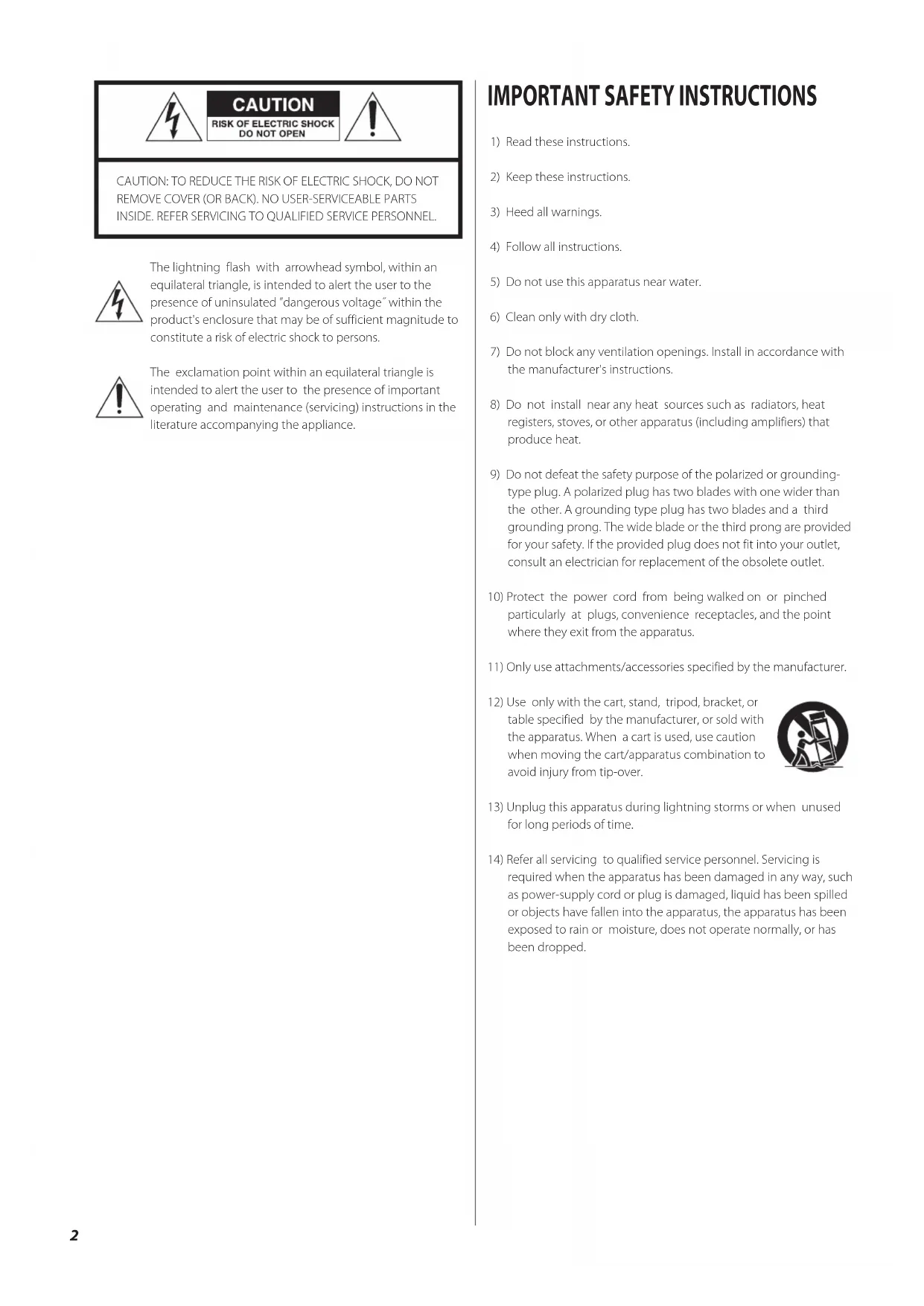
1) Read these instructions.
2) Keep these instructions.
3) Heed all warnings.
4) Follow all instructions.
5) Do not use this apparatus near water.
6) Clean only with dry cloth.
7) Do not block any ventilation openings. Install in accordance with
the manufacturer's instructions.
8) Do not install near any heat sources such as radiators, heat
registers, stoves, or other apparatus (including amplifiers) that produce heat.
9) Do not defeat the safety purpose of the polarized or grounding-
type plug. A polarized plug has two blades with one wider than the other. A grounding type plug has two blades and a third grounding prong. The wide blade or the third prong are provided for your safety. If the provided plug does not fit into your outlet, consult an electrician for replacement of the obsolete outlet.
10) Protect the power cord from being walked on or pinched
particularly at plugs, convenience receptacles, and the point where they exit from the apparatus.
11) Only use attachments/accessories specified by the manufacturer.
12) Use only with the cart, stand, tripod, bracket, or
table specified by the manufacturer, or sold with the apparatus. When a cart is used, use caution when moving the cart/apparatus combination to avoid injury from tip-over.
13) Unplug this apparatus during lightning storms or when unused
for long periods of time.
14) Refer all servicing to qualified service personnel. Servicing is
required when the apparatus has been damaged in any way, such as power-supply cord or plug is damaged, liquid has been spilled or objects have fallen into the apparatus, the apparatus has been exposed to rain or moisture, does not operate normally, or has been dropped. CAUTION: TO REDUCE THE RISK OF ELECTRIC SHOCK, DO NOT REMOVE COVER (OR BACK). NO USER-SERVICEABLE PARTS INSIDE. REFER SERVICING TO QUALIFIED SERVICE PERSONNEL. The lightning flash with arrowhead symbol, within an equilateral triangle, is intended to alert the user to the presence of uninsulated ”dangerous voltage˝ within the product's enclosure that may be of sufficient magnitude to constitute a risk of electric shock to persons. The exclamation point within an equilateral triangle is intended to alert the user to the presence of important operating and maintenance (servicing) instructions in the literature accompanying the appliance.3 CAUTION < DO NOT REMOVE THE EXTERNAL CASES OR CABINETS TO EXPOSE THE ELECTRONICS. NO USER SERVICEABLE PARTS ARE INSIDE. < IF YOU ARE EXPERIENCING PROBLEMS WITH THIS PRODUCT, CONTACT TEAC FOR A SERVICE REFERRAL. DO NOT USE THE PRODUCT UNTIL IT HAS BEEN REPAIRED.
WARNING: TO PREVENT FIRE OR SHOCK HAZARD,
DO NOT EXPOSE THIS APPLIANCE TO RAIN OR MOISTURE. This equipment has been tested and found to comply with the limits for a Class B digital device, pursuant to Part 15 of the FCC Rules. These limits are designed to provide reasonable protection against harmful interference in a residential installation. This equipment generates, uses, and can radiate radio frequency energy and, if not installed and used in accordance with the instru c tion s, may cause harmful inter ference to radio communications. However, there is no guarantee that interference will not occur in a particular installation. If this equipment does cause harmful interference to radio or television reception, which can be determined by turning the equipment off and on, the user is encouraged to try to correct the interference by one or more of the following measures:
- Reorient or relocate the equipment and/or the receiving antenna.
- Increase the separation between the equipment and receiver.
- Connect the equipment into an outlet on a circuit different from that to which the receiver is connected.
- Consult the dealer or an experienced radio/TV technician for help. CAUTION Changes or modifications to this equipments not expressly approved by TEAC CORPORATION for compliance will void the user's warranty. For U.S.A. < Do not expose this apparatus to drips or splashes. < Do not place any objects filled with liquids, such as vases, on the apparatus. < Do not install this apparatus in a confined space such as a book case or similar unit. < The apparatus draws nominal non-operating power from the AC outlet with its POWER or STANDBY/ON switch not in the ON position. < The apparatus should be located close enough to the AC outlet so that you can easily grasp the power cord plug at any time. < The mains plug is used as the disconnect device, the disconnect device shall remain readily operable. < Products with Class ! construction are equipped with a power supply cord that has a 3-prong grounding plug. The cord of such a product must be plugged into an AC outlet that has a protective grounding connection. < If the product uses batteries (including a battery pack or installed batteries), they should not be exposed to sunshine, fire or excessive heat. < Caution should be taken when using earphones or headphones with the product because excessive sound pressure (volume) from earphones or headphones can cause hearing loss.4 Contents Before Use What's in the box Please confirm that the following accessories are in the box when you open it. Power cord x 1 Felt pads x 3 Owner's manual x 1 Warranty card x 1 Read this before operation < Place the unit in a stable location near the audio system that you will use. < Be careful to avoid injury when moving the unit due to its weight. Get someone to help you if necessary. < To protect easily scratched furniture, you may stick the feltpads supplied with the unit to the feet. < As the unit may become warm during operation, always leave sufficient space around the unit for ventilation. Make sure there is at least 20 cm (8”) of space above and at least 5 cm (2”) of space on each side of the unit. Do NOT place anything such as a CD, CD-R, LP, cassette tape etc. on top of the unit. < The voltage supplied to the unit should match the voltage as printed on the rear panel. If you are in any doubt regarding this matter, consult an electrician. < Choose the installation location of your unit carefully. Avoid placing it in direct sunlight or close to a source of heat. Also avoid locations subject to vibrations and excessive dust, heat, cold or moisture. < Do not open the cabinet as this might result in damage to the circuitry or electrical shock. If a foreign object should get into the unit, contact your dealer or service company. < When removing the power plug from the wall outlet, always pull directly on the plug, never yank on the cord. < Keep this manual in a safe place for future reference. Maintenance If the surface of the unit gets dirty, wipe with a soft cloth or use diluted neutral cleaning liquid. Be sure to remove any fluid completely. Do not use thinner, benzine (naphtha) or alcohol as they may damage the surface of the unit. For the sake of safety, disconnect the power plug before cleaning. Placement of the unit High-quality hardened tool steel is used for the pin-point feet, securely attached to the bottom of the unit. < Although the outer feet may appear loose, the weight of the unit causes them to become firm and secure. The design effectively damps and reduces vibration. < To protect the supporting furniture surface, you may stick the felt pads supplied with the unit to the bottom of the metal feet. Steel foot Pin-point foot Cover foot retaining screwsCover foot Bottom plate of the unit Thank you for choosing Esoteric. Read this manual carefully to get the best performance from this unit. Contents . . . . . . . . . . . . . . . . . . . . . . . . . . . . . . . . . . . . . . . . . . . . . . . . . . . . . . . . . . . .4 Before Use ...........................................................4 Features .............................................................5 Connections .........................................................6 Identifying the Parts . . . . . . . . . . . . . . . . . . . . . . . . . . . . . . . . . . . . . . . . . . . . . . . . .8 Troubleshooting .....................................................9 Specifications ........................................................9 Block diagram . . . . . . . . . . . . . . . . . . . . . . . . . . . . . . . . . . . . . . . . . . . . . . . . . . . . . 10 For European customers Disposal of electrical and electronic equipment (a) All electrical and electronic equipment should be disposed of separately from the municipal waste stream via collection facili- ties designated by the government or local authorities. (b) By disposing of electrical and electronic equipment correctly, you will help save valuable resources and prevent any potential negative effects on human health and the environment. (c) Improper disposal of waste electrical and electronic equipment can have serious effects on the environment and human health because of the presence of hazardous substances in the equipment. (d) The Waste Electrical and Electronic Equipment (WEEE) symbol, which shows a wheeled bin that has been crossed out, indicates that electrical and electronic equipment must be collected and disposed of separately from household waste. (e) Return and collection systems are available to end users. For more detailed information about the disposal of old electrical and electronic equipment, please contact your city office, waste disposal service or the shop where you pur- chased the equipment.ENGLISH
A design concept based on a complete commitment to quality Built according to the separate-chassis implementation of our high-end models, the E-03 is a phonostage preamplifier designed to produce the optimum in sound quality from audio signals on an analog record. Functionality has been purposely kept simple while the number of circuits has been reduced. The design we have used for high-quality sound technology is a dual monaural configuration with separate power supplies and seperate audio circuits. Dual monaural configuration The right and left channels are isolated onto separate circuit boards. Similarly, each channel is equipped with its own power supply and R-core power transformer. Since right and left channels do not share these resources, the signal path and separation characteristics are ideal and power supply capacity is exceptional. A symmetrical interior layout adds to physical stability and reduces noise. Audio circuits The audio circuits are built from discrete components only. The amplifier circuit is composed of the moving coil (MC) head amplifier, which amplifies the minute signal levels output by the MC cartridge to the same level as a MM cartridge output, the RIAA amplifier, which amplifies the signals to line output while obtaining RIAA characteristics, and an output buffer amplifier. In the MC head amplifier that handles minute signals, development efforts were concentrated on preserving the purity of the audio signal. Use of an NF-CR type RIAA amplifier has made it possible to balance excellent RIAA characteristics with reduced NF (negative feedback). A high-power supply voltage provides an amplification factor of about 40 dB giving plenty of headroom. The output buffer amplifier is also a high-voltage driver circuit that can transfer a variety of audio signals to an external preamplifier with ease. Features Support for multiple cartridge types Since we regarded support for the variety of MC cartridges available essential, we have MC-compliant equipped two input circuits with a wide range of load resistance (load impedance) values. A 100 Ω or larger load resistance used to be the norm, but MC cartridges with very low internal resistance are now common and phonoamplifiers offering low-load resistance have become possible. By contrast, the recommended load resistance for MM cartridges is primarily 47 kΩ or 50 kΩ while the recommended load capacity has a greater range. The MM mode of the INPUT #2 terminal makes it possible to adjust to a wide range of load capacities. A simple configuration The E-03 design avoids the use of microprocessors to eliminate microprocessor noise. To optimize the signal path, relays handle all switching of inputs and loads directly on to the audio circuit boards without routing signals to the mechanical switches on the front panel. The number of switching functions has been kept to a minimum to reduce the number of circuits the audio signal has to go through. This attention to detail is required in the development of a phonostage preamplifier due to the delicate signals that they must process. Cabinet Construction The two-part chassis design prevents leakage flux from the power transformer from effecting the audio circuits and effectively improves cabinet rigidity. Three pinpoint feet made of quenched steel, a feature unique to Esoteric, help to ensure a vibration-free structure.6 Connections Connection Precautions: < Connect the power plug to a wall socket after completing all other connections. < Be sure to thoroughly read through the instruction manuals of the equipment you will connect and observe all instructions.
Phono input terminal [INPUT 1/INPUT 2] Connect the audio output of the turntable to this terminal. If the turntable is provided with cables, connect the red pin plug to the R terminal and the white pin plug to the L terminal. If the turntable is provided with audio output terminals, connect a commercially available RCA audio cable to the turntable outputs and connect the R and L plugs at the other end to the R and L input terminals on this phonostage preamplifier. INPUT 1 terminal is a MC cartridge input terminal. INPUT 2 terminal is designed for a MC cartridge or a MM cartridge. Be sure to use the INPUT 2 terminal for MM cartridges and inputs from MC cartridges that are routed via a step-up transformer. This terminal is also convenient for users who frequently switch MC and MM cartridges as there is no need to change phono cables.
Line output terminals [LINE OUT] These terminals output audio signals. Connect these terminals to the audio input terminals (LINE IN) on a preamplifier using a commercially available RCA audio cable. < Do not connect the line output terminals of this unit to the phono input terminals on a preamplifier. Be sure to use AUX or other line input terminals.
Ground terminal [SIGNAL GND] Connect the ground terminal on the audio output cable of the record player to this terminal. Making a ground connection to the preamplifier may also help to improve sound quality. < Note that this is not an electrical safety ground connection. < Failure to connect the ground terminal of the record player may generate hum (a low continuous noise).
Power cord Connect the power cord to the power cord receptacle, and connect the power plug to an AC wall socket, after all other connections have been made. < Use only the supplied power cord. Use of other power cords may result in fire or electric shock. Unplug the power cord when you are not going to use the unit for several weeks. Esoteric uses Esoteric MEXCEL stress-free 7N cable as a reference. The following items are available in the Esoteric MEXCEL cable series. RCA audio cable BNC digital cable XLR audio cable Speaker cable RCA digital cable Power cable XLR digital cable8 Identifying the Parts
POWER Turns the power on and off. When the unit is on, the periphery of the button lights blue. < Turns off the power when not using this unit.
INPUT 2 Set these controls for each terminal to suit the connected turntable based on the cartridge installed. If the MC cartridge used has a recommended load resistance (load impedance), set the controls to a position near this value. If not, select the position that produces the best sound quality. Lower load resistance will lower the sound volume while a higher load resistance will raise it. < Load resistance does not refer to the resistance inside the cartridge (internal impedance, coil impedance). < Select a load resistance that is adequately large relative to the internal resistance of the cartridge that you use. < Selecting a load resistance that is not large enough relative to internal cartridge resistance will reduce sound volume and increase noise. INPUT 2 A MM cartridge can be connected to INPUT 2. The load resistance for MM cartridges is fixed at 47 kΩ. If a specific load capacity is specified for the MM cartridge you use, select a position close to this value. If not specified, try using the 0pF position and select the load capacity of your choice. Using the auto demagnetization function The auto demagnetization function demagnetizes the iron core in the MC cartridge and the step-up transformer to restore transparency and definition to playback sound.
1. Use the INPUT 1 or 2 control knob to select the DEMAG
position for the cartridge you want to demagnitize. The load impedance is set to 0 Ω and both ends of the cartridge are short-circuited.
2. Playback a record.
The current goes through the cartridge to demagnetize it. < It will take about 30 seconds to demagnetize a cartridge. < In DEMAG position, no playback sound is output.ENGLISH
SpecificationsTroubleshooting If you experience any problem with this unit, please take the time to look through this chart and see if you can solve the problem yourself before calling your dealer. No power e Connect the power plug to a wall socket. There is no sound. e Turn the power on. e Turn the input selector knob to select an input source. e No playback sound is output when the INPUT 1 or INPUT 2 control knob is set to DEMAG. Turn the INPUT 1 or INPUT 2 control knob away from the DEMAG position. Sound is too low e The rated output of this unit is 0.5 V, which is lower than a CD player. Adjust the volume control on the preamplifier. If you use the C-03 preamplifier, set the input level (Level>) of the input terminal to which this unit is connected a little high so that only a small amount of volume adjustment is required when you change the input source. Too much noise e Selecting a load resistance that is not adequate for the internal resistance of a cartridge reduces the sound volume and raises noise levels. Turn the Input control knob to select a load resistance that is sufficiently large for the internal resistance of the cartridge you are using. e If not connected, connect the GND terminal of the cable from the record player to the ground terminal of this unit. Audio characteristics (1kHz) RIAA deviation (20Hz to 20kHz) ...........................±0.2 dB Total harmonic distortion (A-weight, MM) ..................0.003% Output impedance ..........................................80 Ω Maximum output level . . . . . . . . . . . . . . . . . . . . . . . . . . . . . . . . . . . . . . .18 V Rated output level ........................................500 mV Gain ..................................................40 dB (MM) 66 dB (MC) Input sensitivity . . . . . . . . . . . . . . . . . . . . . . . . . . . . . . . . . . . . . . . 5 mV (MM)