PALPKITDGW - Oven THERMADOR - Free user manual and instructions
Find the device manual for free PALPKITDGW THERMADOR in PDF.

User questions about PALPKITDGW THERMADOR
0 question about this device. Answer the ones you know or ask your own.
Ask a new question about this device
Download the instructions for your Oven in PDF format for free! Find your manual PALPKITDGW - THERMADOR and take your electronic device back in hand. On this page are published all the documents necessary for the use of your device. PALPKITDGW by THERMADOR.
USER MANUAL PALPKITDGW THERMADOR
natural_image
Black-and-white photo of a plated seafood dish featuring whole fish, shrimp, lemon slices, and garnishes (no text or symbols visible)Installation
INSTRUCTIONS
Pro Harmony ^® , Pro Grand ^® , and Pro Rangetop Propane (LP) Conversion Kit
Table of contents (English) 3
IMPORTANT SAFETY INSTRUCTIONS .... 4
Propane (LP) gas conversion instructions .... 6
Before you begin 6
Checklist 7
Installation procedure 9
Disassembling the rangetop 9
Converting the regulator to LP 9
Changing "D" and "F" STAR burner orifices only 10
Changing "B" STAR burners (305 models only) and/or "D" and "F" STAR burners .... 11
Propane (LP) burner orifice conversion tables ..... 11
Changing the broil orifice, on GAS ranges only .. 15
Changing the bake orifice, on GAS ranges only . 17
Checking for gas leaks 19
Checking the flame and burner performance .... 20
Setting the STAR burner valve screws 21
Placing the conversion label 22
Support, accessories, and parts ...... back page
Safety definitions
⚠ WARNING: This indicates that death or serious injuries may occur as a result of non-observance of this warning.
⚠ CAUTION: This indicates that minor or moderate injuries may occur as a result of non-observance of this warning.
NOTICE: This indicates that damage to the appliance or property may occur as a result of non-compliance with this advisory.
Note: This alerts you to important information and/or tips.
This Thermador ^® appliance is made by
BSH Home Appliances Corporation
1901 Main Street, Suite 600
Irvine, CA 92614
Questions?
1-800-735-4328
www.thermador.com or www.thermador.ca
We look forward to hearing from you!
⚠️ IMPORTANT SAFETY INSTRUCTIONS READ AND SAVE THESE INSTRUCTIONS
Please read carefully
Save the original gas parts for possible conversion back in the future.
Important: Only a qualified service technician or installer should make this conversion.
Installer: Please leave these instructions with this unit for the owner.
Owner: Please retain these instructions for future reference.
WARNING
If the information in this manual is not followed exactly, a fire or explosion may result causing property damage, personal injury, or death.
-- DO NOT store or use gasoline or other flammable vapors and liquids in the vicinity of this or any other appliance.
-- WHAT TO DO IF YOU SMELL GAS
- DO NOT try to light any appliance.
- DO NOT touch any electrical switch.
• DO NOT use any phone in your building.
- Immediately call your gas supplier from a neighbor's phone. Follow the gas supplier's instructions.
- If you cannot reach your gas supplier, call the fire department.
-- Installation and service must be performed by a qualified installer, service agency or the gas supplier.
This kit is for converting Thermador appliances for operation with propane (LP) gas. This kit contains orifices for proper LP conversion for oven bake, broiler, and top surface STAR ^® burners.
A High Altitude kit is required for propane (LP) units installed at altitudes of 10,000 ft. (3,048 m) and greater elevation above sea level. Please see the back cover for information about service, parts, and accessories.
This kit is used to convert select models of Pro Rangetop, Pro Harmony, and Pro Grand ranges to propane (LP) gas usage. This kit cannot be used to convert older models of rangetops or ranges. This kit cannot be used to convert any other brand of appliance.
WARNING
This conversion kit shall be installed by a qualified service agency in accordance with the manufacturer's instructions and all applicable codes and requirements of the authority having jurisdiction. In any case, the installation of this conversion kit must conform with local codes or, in the absence of local codes, with the National Fuel Gas Code, ANSI Z223.1/NFPA 54 or, in Canada, the Natural Gas and Propane Installation Code, CSA B149, latest edition. If the information in these instructions is not followed exactly, a fire, explosion or production of carbon monoxide may result causing property damage, personal injury, or loss of life. The qualified service agency is responsible for the proper installation of this kit. The installation is not proper and complete until the operation of the converted appliance is checked as specified in the manufacturer's instructions supplied with the kit.
WARNING
Never Operate the Top Surface Cooking Section of this Appliance Unattended
- Failure to follow this warning statement could result in fire, explosion, or burn hazard that could cause property damage, personal injury, or death.
- If a fire should occur, keep away from the appliance and immediately call your fire department. DO NOT ATTEMPT TO EXTINGUISH AN OIL/GREASE FIRE WITH WATER.
For Massachusetts installations
-
Installation must be performed by a qualified or licensed contractor, plumber, or gas fitter qualified or licensed by the state, province or region.
-
Shut-off valve must be a "T" handle gas cock.
-
Flexible gas connector must not be longer than 36 inches.
⚠️ IMPORTANT SAFETY INSTRUCTIONS READ AND SAVE THESE INSTRUCTIONS
The following must be met when testing supply piping system:
- The appliance and its individual shut-off valve must be disconnected from the gas supply piping system at test pressures in excess of 1/2 psig (3.5 kPa).
- The appliance must be isolated from the gas supply piping system by closing its individual manual shut-off valve during any pressure testing of the gas supply piping system at test pressures equal to or less than 1/2 psig (3.5 kPa).
CAUTION
When connecting the unit to propane gas, make certain the propane gas tank is equipped with its own high pressure regulator. The maximum gas pressure to this appliance is not to exceed 14.0 inches water column (3.5 kPa) from the propane gas tank regulator.
The minimum propane (LP) gas supply pressure for the checking of the gas appliance pressure regulator, when converted for use with propane gas, must be between 11 inches water column (2.7 kPa) and 14 inches water column (3.5 kPa). Please refer to p. 9 on to how to properly convert the gas pressure regulator for use with propane (LP) gas.
WARNING
Never leave the gas conversion partially completed. If the appliance is operated while the gas conversion is incomplete, high levels of carbon monoxide may be emitted, or a fire or explosion may occur, causing property damage, personal injury, or death.
Save the original natural gas orifices removed from the appliance for future use. Make sure that you carefully mark and label these orifices, indicating the correspondent burner from which they were removed.
To convert the appliance back for use with natural gas, follow these instructions exactly, but replacing the propane gas orifices with the original natural gas ones. Carefully match their correspondent burners as previously marked and labeled.
To the service agent
It is important that you know the following BEFORE you begin the conversion of the appliance.
- Confirm that the gas supply system is available and ready to use. This is particularly important for new construction.
- Verify the type of gas supplied to the location. Ensure that the appliance is connected to the type of gas for which it is certified.
- You must plan for sufficient time and resources to perform the conversion process properly and completely before leaving the job site. Every step described in these instructions must be performed to safely convert the appliance for proper operation with propane (LP) gas. INCOMPLETE OR INADEQUATE CONVERSION OF THE APPLIANCE CAN CREATE A SAFETY HAZARD.
Proposition 65 Warning
This product may contain a chemical known to the State of California, which can cause cancer or reproductive harm. Therefore, the packaging of your product may bear the following label as required by California:
State of California Proposition 65 Warning:
⚠ WARNING
Cancer and Reproductive Harm - www.P65Warnings.ca.gov
Propane (LP) gas conversion instructions
Before you begin
CAUTION
Before proceeding with the conversion, shut off the gas supply to the appliance prior to disconnecting the electrical power.
Disconnect the appliance from electrical power by unplugging the electrical cord from its receptacle or by disconnecting power at the circuit breaker box.
Tools needed
• T-20 star-head driver
- 7/16" box end wrench
• 13/16" box end wrench
- 7 mm or a 9/32" socket
- 1/4" nut driver
- 16 mm hex bit or 5/8" hex bit
• T-30 star-head driver
- 1/2" offset box end wrench
- 9 mm hex bit
• 9/32" open end wrench
- 7/8" socket or 7/8" open end wrench
- Adjustable wrench
- Soap and water mixture or leak-check solution
Pro Grand propane (LP) burner orifice conversion kits
| PALPKITDGW | For all Pro Grand dual fuel ranges |
| PALPKITGGW | For all Pro Grand gas ranges |
| Pro Harmony ranges and Pro Rangetops propane (LP) burner orifice conversion kits | |
| PALPKITHW For Pro Harmony dual fuel ranges and Pro Rangetops with 4 and 6 STAR® burners | |
| PALKITHW5 For Pro Harmony dual fuel ranges and Pro Rangetops with 5 STAR® burners | |
| PALPKITHA5 For Pro Harmony gas ranges with 5 STAR® burners | |
| PALPKITGA For Pro Harmony 30'' and 36'' gas ranges with 4 and 6 STAR® burners | |
| PALPKITGA6 For Pro Harmony 48'' gas ranges with 4 and 6 STAR® burners | |
LP gas kit parts included
| Gas Pro Harmony ranges with 5 STAR® burners (PRG305WH) | Qty |
| Conversion label 1 | |
| Foam tape, 1" piece 1 | |
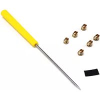
| Screwdriver 1 | |
| Orifice, 0.73 mm (73), STAR® burners 2 | |
| Orifice, 0.90 mm (90), STAR® burners 1 | |
| Orifice, 1.05 mm (105), STAR® burners 1 | |
| Orifice, 1.15 mm (115), STAR® burners 1 | |
| Orifice, 1.34 mm (134), main oven bake 1 | |
| Orifice, 1.30 mm (130), main oven broil 1 | |
| Dual Fuel Pro Harmony ranges and Pro Rangetop with 5 STAR® burners (PRD305WH(U/C) or PCG305W) | Qty |
| Conversion label 1 | |
| Foam tape, 1" piece 1 | |
| Screwdriver 1 | |
| Orifice, 0.73 mm (73), STAR® burners 2 | |
| Orifice, 0.90 mm (90), STAR® burners 1 | |
| Orifice, 1.05 mm (105), STAR®burners 1 | |
| Orifice, 1.15 mm (115), STAR®burners 1 | |
| Dual Fuel Pro Harmony ranges and Pro Rangetop with 4 or 6 STAR®burners | Qty |
| Conversion label 1 | |
| Foam tape, 1" piece 1 | |
| Screwdriver 1 | |
| Orifice, 1.05 mm (105), STAR®burners 3 | |
| Orifice, 1.15 mm (115), STAR®burners 3 | |
| Gas Pro Harmony 48" ranges with 4 or 6 STAR®burners | Qty |
| Conversion label 1 | |
| Foam tape, 1" piece 1 | |
| Screwdriver | 1 |
| Orifice, 1.05 mm (105), STAR®burners 3 | |
| Orifice, 1.15 mm (115), STAR®burners 3 | |
| Orifice, 1.34 mm (134), main oven bake 1 | |
| Orifice, 1.17 mm (117), aux oven bake 1 | |
| Orifice, 1.25 mm (125), main oven broil | 1 |
| Orifice, 0.82 mm (82), aux oven broil | 1 |
| Gas Pro Harmony 30'' and 36'' ranges with 4 or 6 STAR® burners | Qty |
| Conversion label 1 | |
| Foam tape, 1'' piece 1 | |
| Screwdriver | 1 |
| Orifice, 1.05 mm (105), STAR® burners 3 | |
| Orifice, 1.15 mm (115), STAR® burners 3 | |
| Orifice, 1.34 mm (134), main oven bake 1 | |
| Orifice, 1.30 mm (130), main oven broil 1 | |
| Dual Fuel Pro Grand ranges with 4 or 6 STAR®burners | Qty |
| Conversion label 1 | |
| Foam tape, 1" piece 1 | |
| Screwdriver 1 | |
| Orifice, 1.05 mm (105), STAR® burners 3 | |
| Orifice, 1.15 mm (115), STAR® burners 2 | |
| Orifice, 1.26 mm (126), STAR® burners 1 |
| Gas Pro Grand ranges with 4 or 6 STAR®burners | Qty |
| Conversion label 1 | |
| Foam tape, 1" piece 1 | |
| Screwdriver 1 | |
| Orifice, 1.05 mm (105), STAR® burners 3 | |
| Orifice, 1.15 mm (115), STAR® burners 2 | |
| Orifice, 1.26 mm (126), STAR® burners 1 | |
| Orifice, 1.46 mm (146), main oven bake 1 | |
| Orifice, 1.13 mm (113), aux oven bake 1 | |
| Orifice, 1.25 mm (125), main oven broil 1 | |
| Orifice, 0.813 mm (813) or "67", aux oven broil* 1 |
*This orifice is stamped "67", which means #67 DMS (Drill Metal Standard, or wire gage number, or drill size) and is dimensionally equal to 0.0320" or 0.813 mm diameter.
Checklist
Each of the following steps must be completed correctly for the appliance to function properly. Check off each step as it is finished.
Pro Rangetop models
| Step 1 Disassemble the rangetop (p. 9). |
| Step 2 Convert the regulator to LP gas (p. 9). |
| Step 3 Change the STAR® burner orifices (p. 10). |
| Step 4 Check the rangetop for gas leaks (p. 19). |
| Step 5 Reassemble the rangetop and check STAR burner flame performance ( p. 20 ). | |
| Step 6 Set the valve screws for the STAR burners ( p. 21 ). | |
| Step 7 Place the conversion label ( p. 22 ). |
Pro Harmony gas models
| Step 1 Disassemble the rangetop ( p. 9 ). |
| Step 2 Convert the regulator to LP gas ( p. 9 ). |
| Step 3 Change the STAR® burner orifices ( p. 10 ). |
| Step 4 Remove the backguard ( p. 15 ). |
| Step 5 Change the main oven broil burner orifice ( p. 15 ). |
| Step 6 48" models – change the aux oven broil burner orifice ( p. 15 ). |
| Step 7 Remove the oven door(s) ( p. 16 ). |
| Step 8 Remove the kick and front panels ( p. 16 ). |
| Step 9 Change the main oven bake burner orifice ( p. 17 ). |
| Step 10 48" models – change the aux oven bake burner orifice ( p. 18 ). |
| Step 11 Reinstall the door(s) ( p. 16 ). |
| Step 12 Check the rangetop and oven for gas leaks ( p. 19 ). |
| Step 13 Reassemble the rangetop and check STAR® burner flame performance ( p. 20 ). |
| Step 14 Set the STAR® burner valve screws ( p. 21 ). |
| Step 15 Check the broil and bake burner flame performance ( p. 20 ). |
| Step 16 Reinstall the kick and front panels ( p. 16 ). |
| Step 17 Place the conversion label ( p. 22 ). |
Pro Harmony dual fuel models
| Step 1 Disassemble the rangetop ( p. 9 ). |
| Step 2 Convert the regulator to LP gas ( p. 9 ). |
| Step 3 Change the STAR® burner orifices ( p. 10 ). |
| Step 4 Check the rangetop for gas leaks ( p. 19 ). |
| Step 5 Reassemble the rangetop and check STAR® burner flame performance ( p. 20 ). |
| Step 6 Set the valve screws for the STAR® burners ( p. 21 ). |
| Step 7 Place the conversion label ( p. 22 ). |
Pro Grand gas models
| Step 1 Disassemble the rangetop ( p. 9 ). |
| Step 2 Convert the regulator to LP gas ( p. 9 ). |
| Step 3 Change the STAR® burner orifices ( p. 10 ). |
| Step 4 Remove the backguard ( p. 15 ). |
| Step 5 Change the main oven broil burner orifice ( p. 15 ). |
| Step 6 48" models – change the aux oven broil burner orifice ( p. 15 ). |
| Step 7 Remove the oven door ( p. 16 ). |
| Step 8 Remove the kick and front panels ( p. 16 ). |
| Step 9 Change the main oven bake burner orifice ( p. 17 ). |
| Step 10 48" models – change the aux oven bake burner orifice ( p. 18 ). |
| Step 11 Reinstall the door(s) ( p. 16 ). |
| Step 12 Check the rangetop and oven for gas leaks ( p. 19 ). |
| Step 13 Reassemble the rangetop and check STAR® burner flame performance ( p. 20 ). |
| Step 14 Set the valve screws for the STAR® burners ( p. 21 ). |
| Step 15 Check the broil and bake burner flame performance ( p. 20 ). |
| Step 16 Reinstall the kick and front panels ( p. 16 ). |
| Step 17 Place the conversion label ( p. 22 ). |
Pro Grand dual fuel models
| Step 1 Disassemble the rangetop ( p. 9 ). |
| Step 2 Convert the regulator to LP gas ( p. 9 ). |
| Step 3 Change the burner orifices ( p. 10 ). |
| Step 4 Check the rangetop for gas leaks ( p. 19 ). |
| Step 5 Reassemble the rangetop and check STAR® burner flame performance ( p. 20 ). |
| Step 6 Set the valve screws for the STAR® burners ( p. 21 ). |
| Step 7 Place the conversion label ( p. 22 ). |
Installation procedure
NOTE: All graphics are representative. Appearances may vary.
Disassembling the rangetop
CAUTION
Before proceeding with the conversion, shut off the gas supply to the appliance prior to disconnecting the electrical power.
Disconnect the appliance from electrical power by unplugging the electrical cord from its receptacle or by disconnecting power at the circuit breaker box.
To disassemble the rangetop
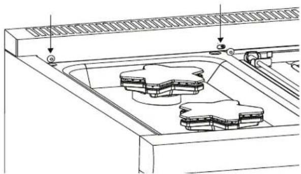
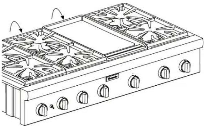
- Remove the rangetop grates and the burner caps.
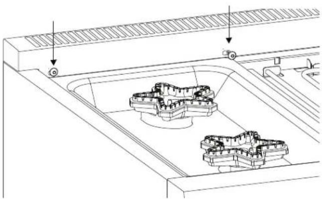
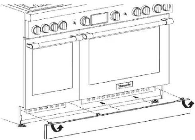
- To facilitate the removal of the spill tray, remove the T-20 star-head screws in the front face of the island trim or backguard.
natural_image
Technical line drawing of a mechanical assembly with two internal components and directional arrows indicating motion (no text or symbols)- Use a 16 mm hex head bit for burners labeled 'D' or 'F'. Use a 9 mm hex head bit for burners labeled 'B' to remove the burner venturi from each burner base.
text_image
Technical diagram showing two mechanical components labeled a and b, with arrows indicating motion or assembly steps.a. Hex head bit b. Burner venturi
TIP: If a 16 mm hex head bit is not readily available, a 5/8" hex bit can be selected. Alternatively, a bolt with 5/8" head either "double-nutted" or tightened into the chuck of a power driver can be used.
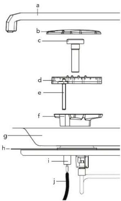
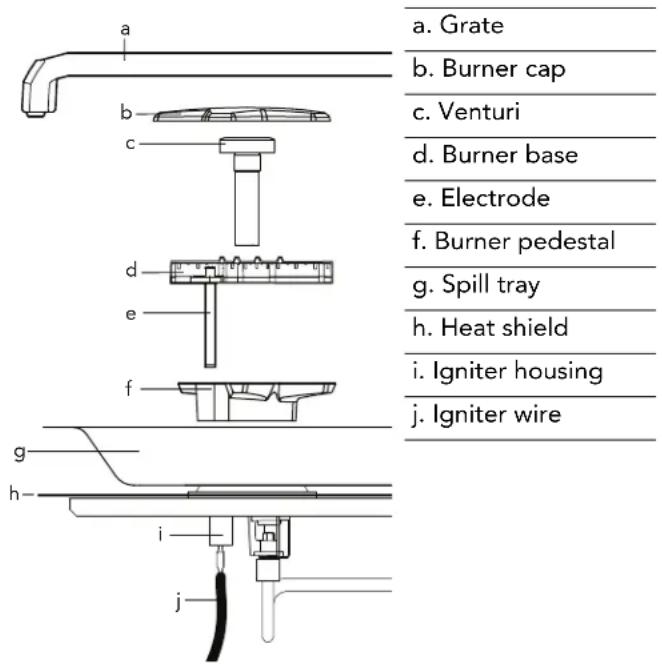
- Disconnect the igniter. Carefully pull up on the burner base.
text_image
a b c d e f g h- i ja. Grate
b. Burner cap
c. Venturi
d. Burner base
e. Electrode
f. Burner pedestal
g. Spill tray
h. Heat shield
i. Igniter housing
j. Igniter wire
- Remove the screw securing the burner pedestal with a T-30 star-head driver. Carefully remove each burner pedestal.
- Remove the spill trays by pivoting the trays up and out the back.
- Remove the heat shield on some models. Some models have a double-width shield that extends under adjacent spill tray.
Converting the regulator to LP
The gas regulator is located in the rangetop, left side of appliance. Exact location will vary per model.
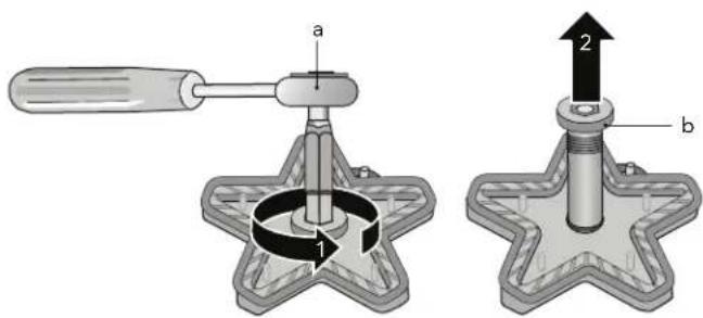
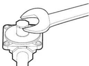
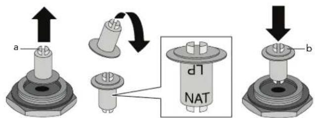
- Remove the conversion cap with a 7/8" socket or wrench, or an adjustable wrench.
natural_image
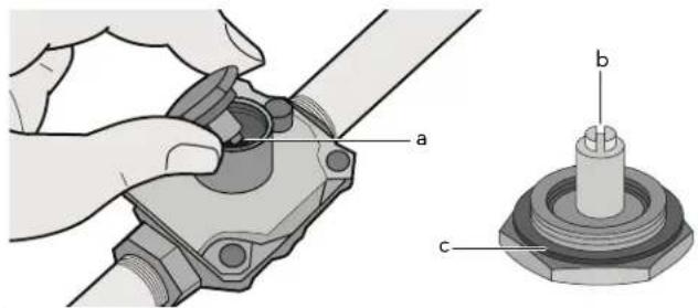
Line drawing of a hand gripping a mechanical component (no text or symbols)- Grasp the plastic button stem firmly and pull it forcefully from the metal cap. The stem snaps snugly into an indent in the cap and may require a strong pull to remove. (Hint: it may be helpful to gently "rock" the plastic stem while pulling it from the metal cap.)
text_image
Technical diagram showing mechanical assembly with labeled parts a, b, and ca. Spring
b. Plastic button stem
c. Gasket
- Rotate the stem 180° so the letters "LP" on the stem are upside down when the cap is set flat on its head. Snap the stem back in place in this position inserting it into the indent in the metal cap. The stem should snap into place.
text_image
a b d7 NATa. Natural gas b. LP gas
- Reinstall conversion cap, configured for LP gas, back into top of the regulator.
Changing "D" and "F" STAR® burner orifices only
To prepare the 7 mm, 9/32" socket, or 1/4" nut driver for STAR® burner orifice conversion
NOTE: This procedure facilitates the changing of the orifices in the "D" and "F" STAR burners only. For the smaller sized "B" burners in 305 models, this procedure will not work because the socket is too big for insertion through the orifice holders. To change "B" size STAR burners, refer to page 11.
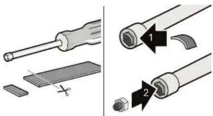
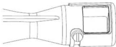
- Trim a small piece of the foam tape provided with this kit to about 1/4 - 1/2" (6 - 12 mm).
- Place foam tape over the edge of a 7 mm or a 9/32" socket, or with 1/4" nut driver used to replace the burner orifices, as shown below.
- The foam tape helps to retain the orifice in the end of the nut driver so it will not fall inside the appliance during orifice removal or installation.
text_image
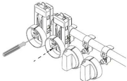
Diagram illustrating screwdriver tool installation steps with labeled parts 1 and 2To replace the STAR® "D" and "F" burner orifices
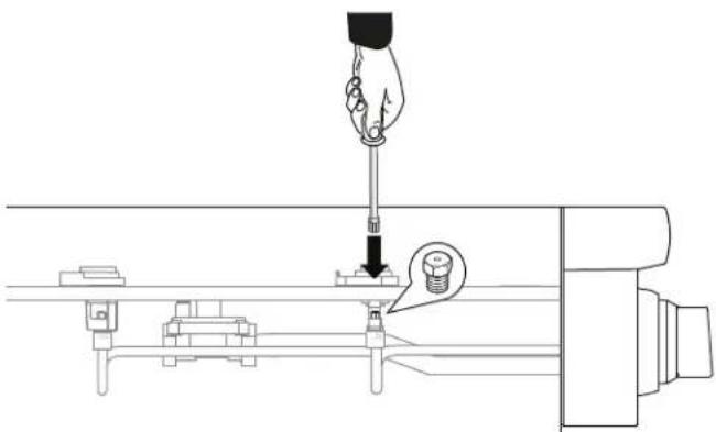
- With the foam tape wrapped nut driver, reach down through the jet holders and remove the gas orifice from the STAR burner's jet holder.
natural_image
Technical line drawing of a hand using a screwdriver to adjust or install a mechanical component (no text or symbols present)- Label each of the removed orifices, noting from which burner they were removed, in the event the appliance is converted back to natural gas in the future.
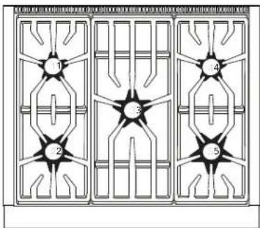
Burner layout legend
For your convenience, note the orifice sizes and locations in the following table.
| Left rear Left center rear Center rear Right center rear Right rear | ||
| Left front Left front center Center front Right center front Right front |
- Locate the proper STAR ^ burner orifices included with the kit. Orifices are stamped with the orifice diameter size on the side.


- Replace orifices as indicated in the tables beginning on page 11. Ensure the orifice is completely seated and tight to the jet holder to avoid possible gas leaks.
NOTE: All of the replacement orifices in the conversion kit have straight threads (not pipe threads) and do not require thread sealing compound.
Changing "B" STAR® burners (305 models only) and/or "D" and "F" STAR® burners
This procedure can be applied when:
- Converting size "B" burners.
- Preferred by the installer to change orifices of any size burner ("B", "D", or "F").
- A 7 mm or 9/32" socket, or 14 " nut driver is not available for use when changing the orifices on "D" and "F" burners.
To replace the "B" STAR® burner orifices (or any burner size orifice)
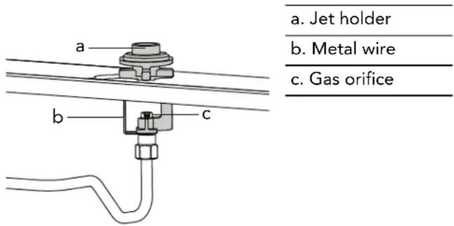
- From the side of the jet holder, insert a 9/32" open end wrench into the space between the metal wire and the jet holder. Remove the gas orifice from the STAR burner's jet holder.
text_image
a. Jet holder b. Metal wire c. Gas orifice-
Label each of the removed orifices, noting from which burner they were removed, in the event the appliance is converted back to natural gas in the future.
-
Locate the proper STAR burner orifices included with the kit. Orifices are stamped with the orifice diameter size on the side.


- Replace orifices as indicated in the tables beginning on page 11. Ensure the orifice is completely seated and tight to the jet holder to avoid possible gas leaks.
NOTE: All the replacement orifices in the conversion kit have straight threads (not pipe threads) and do not require thread sealing compound.
Pro Harmony ranges and Pro Rangetops propane (LP) STAR® burner orifice conversion kits
| PALPKITHW For Pro Harmony dual fuel ranges and Pro Rangetops with 4 and 6 STAR® burners | |
| PALKITHW5 | For Pro Harmony dual fuel ranges and Pro Rangetops with 5 STAR® burners |
| PALPKITHA5 | For Pro Harmony gas ranges with 5 STAR® burners |
| PALPKITGA | For Pro Harmony 30" and 36" gas ranges with 4 and 6 STAR® burners |
| PALPKITGA6 | For Pro Harmony 48" gas ranges with 4 and 6 STAR® burners |
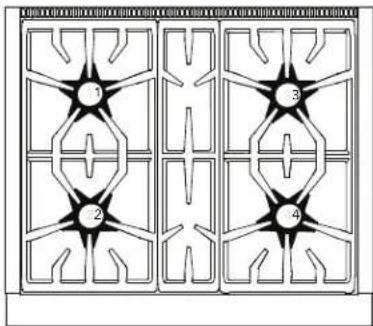
Model 304
natural_image
Symmetrical geometric pattern with four numbered star-like shapes arranged in a grid (no text or symbols)| (1) 105 (3) 105 | |
| (2) 115 (4) 115 |
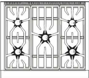
Model 305
flowchart
graph TD
    A["1"] --> B["2"]
    B --> C["3"]
    C --> D["4"]
    D --> E["5"]
Model 364 with griddle
text_image
1 2 3 4 5| (1) 105 | (3)— | (4) 105 |
| (2) | 115 |
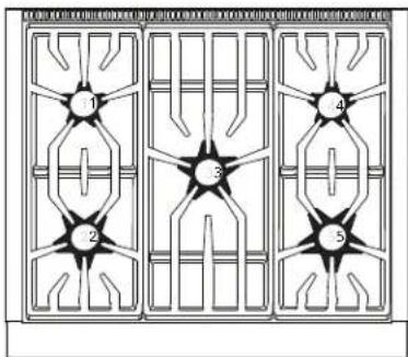
Model 366

natural_image
Three identical geometric panels with six star-shaped patterns arranged in a grid (no text or symbols)| (1) 105 (3) 105 (5) 105 | ||||
| (2) | 115 | (4) | 115 | (6) |
Model 364 with grill
text_image
1 2 3 4 5| (1) 105 | (3)—115 | (4) 105 |
| (2) |
Model 486 with grill
text_image
1 2 3 4 5 6 7| (1) 105 (3) 105 | (5)—115 | (6) 105 | ||||
| (2) | 115 | (5) | (4) | (7) | 115115 | |
Model 486 with griddle
text_image
1 2 3 4 5 6 7| (1) 105 (3) 105 | (5)— | (6) 105 | |
| (2) 115 (4) 115 | (7) 115 |
Model 486 with griddle and grill
text_image
1 2 3 4 5 6| (1) 105 (3) 105 (5) — | ||
| (2) 115 | (4) | 115 |
Pro Grand propane (LP) STAR® burner orifice conversion kits
| PALPKITDGW | For all Pro Grand dual fuel ranges |
| PALPKITGGW | For all Pro Grand gas ranges |
Model 364 with griddle
text_image
1 2 3 4 5| (1) 105 | (3)— | (4) 105 |
| (2) 126 (5) 115 |
Model 366
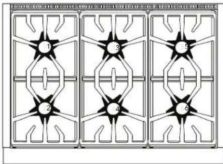
natural_image
Three identical geometric star patterns arranged in a 2x2 grid, no text or symbols present.| (1) 105 (3) 105 (5) 105 | |
| (2) 126 (4) 115 (6) 115 |
Model 364 with grill
text_image
1 2 3 4 5| (1) 105 | (3)—— | (4) 105 |
| (2) 126 (5) 1(6)5 |
Model 364 with induction
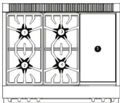
text_image
1 2 3 4 5| (1) 105 (3) 105 | (5)— | |
| (2) 126 (4) 115 |
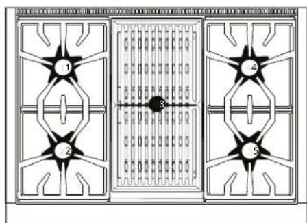
Model 486 with induction
natural_image
Diagram of a three-panel window with star patterns and a door, no text or symbols present| (1) 105 (3) 105 (5) 105 | (7)— | |
| (2) 126 (4) 115 (6) 115 |
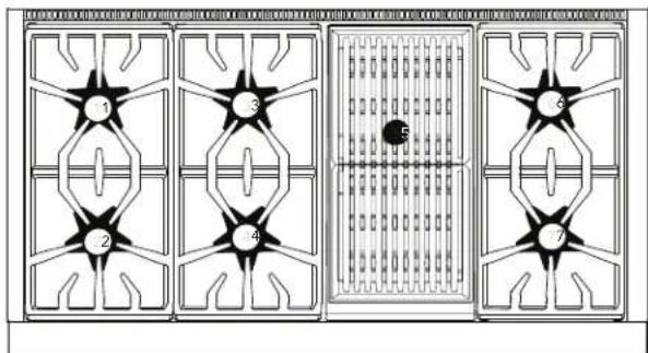
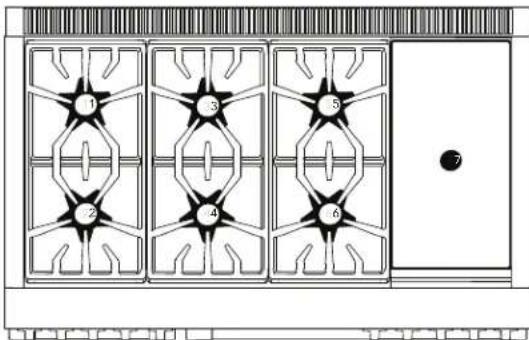
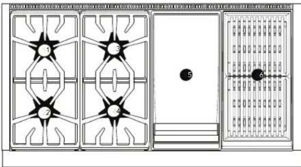
Model 486 with grill
text_image
1 2 3 4 5 6 7| (1) 105 (3) 105 | (5)— | (6) 105 | |
| (2) 126 (4) 115 | (7) 115 |
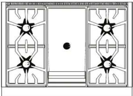
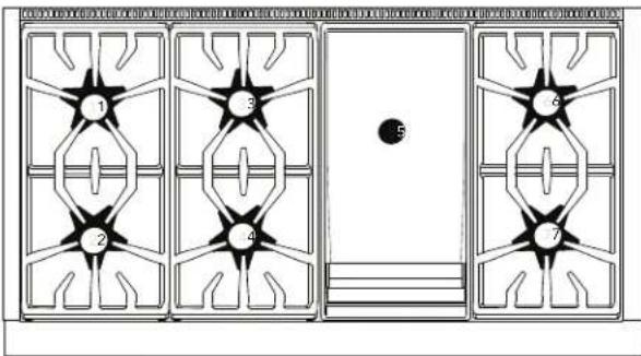
Model 486 with griddle
text_image
1 2 3 4 5 6 7| (1) 105 (3) 1 | 05 | (5)— | (6) 105 |
| (2) 126 (4) 1 | 15 (7) 115 |
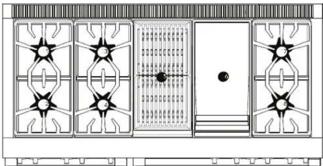
Model 486 with griddle and grill
text_image
1 2 3 4 5 6| (1) 105 (3) 105 ($) — | |
| (2) 126 (4) 115 (6) — |
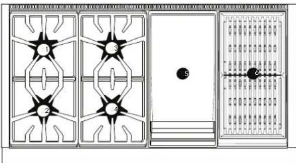
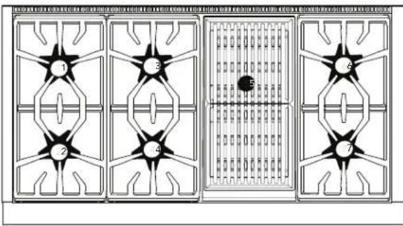
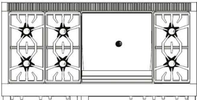
Model 606 with grill and griddle
natural_image
Architectural floor plan showing four window-like furniture units with numbered star patterns and a central door (no text or symbols)| (1) 105 (3) 105 (5)—(7) 105 | ||
| (2) 126 (4) 115 (6)—(8) 115 |
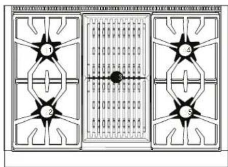
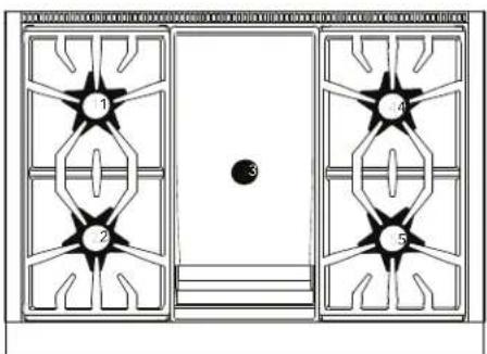
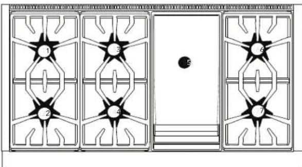
Model 606 with griddle
natural_image
Architectural floor plan showing four window-like furniture units with numbered star patterns and a central circular object (no text or symbols)| (1) 105 (3) 105 | (5)— | (6) 105 |
| (2) 126 (4) 115 (7) 115 |
Changing the broil orifice, on GAS ranges only (PRG models)
CAUTION
After the replacement of the broiler orifice, and before reassembly of the back panel and backguard to the range, perform a brief gas leakage check of the orifice and associated fittings, per the "Check for Gas Leaks" section of these instructions.
Removing the backguard assembly
- Move the range out of its installed position to gain full access to the rear panel of the backguard assembly and to the broil burners' orifices.
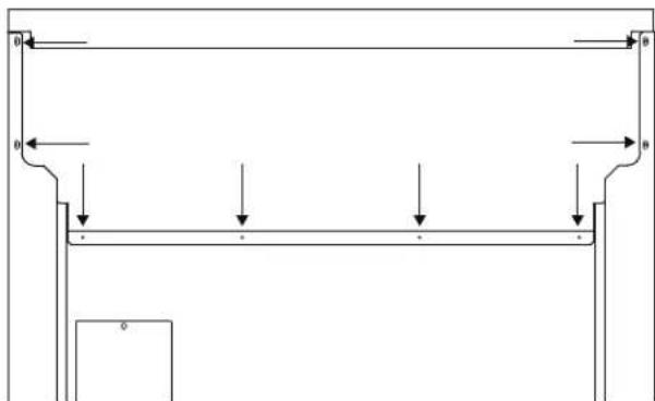
- Use a T-20 star-head screwdriver to remove the screws from the front of the backguard assembly.
natural_image
Technical line drawing of a mechanical assembly with two internal components and mounting holes (no text or symbols)- Use a T-20 star-head screwdriver to remove the screws from the back rear panel of the backguard assembly.
natural_image
Pure mechanical diagram showing a structural frame with arrows indicating forces or motion, no text or symbols present.- Carefully lift the backguard assembly from the range.
Changing the broil burner orifice
NOTE: This procedure applies to both the main oven broil burner and, when applicable, to the auxiliary oven broil burner.
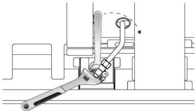
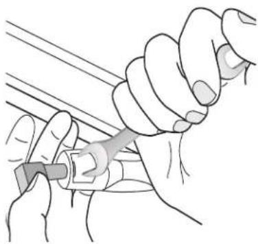
- Remove broil orifice using a 7/16" box end wrench, while restraining the elbow fitting from rotation using a small adjustable wrench.
natural_image
Technical diagram of a mechanical switch mechanism with no visible text or symbolsIMPORTANT: DO NOT bend the broil burner orifice bracket. Ensure that the broiler orifice is aligned to the center of the burner tube inlet.
- Label each of the removed orifices, noting from which burner they were removed, in the event the appliance is converted back to natural gas in the future.
For your convenience, note the orifice sizes and locations in the following table.
| Main oven broil Aux | oven broil |
-
Locate the proper burner orifices included with the kit. Orifices are stamped with the orifice diameter size on the side.
-
Replace orifices as indicated in the table. To avoid any possible gas leak in this area, ensure the orifice is completely seated and tight to the burner orifice holding bracket and the 90° orifice elbow.
Pro Grand
| Model Main oven broil Aux oven broil | |
| All models 1.25 mm (125) 0.813 mm (813) or "67" |
Pro Harmony
| Model Main oven broil Aux oven broil | |
| 30" & 36" 1.30 (130) — | |
| 48" 1.25 (125) 0.82 mm (82) | |
NOTE: The replacement broil orifices have straight threads (not tapered threads) and DO NOT require thread sealing compound.
- Continue to "Removing and installing the oven door(s), on GAS ranges only (PRG models)" before reattaching the backguard assembly. Once all of the broil and bake burners' orifices have been replaced and converted to LP gas, reinstall the oven doors before performing a gas leak check of all the replaced bake and broil orifices and their associated supply tube fittings.
Removing and installing the oven door(s), on GAS ranges only (PRG models)
CAUTION
- USE CAUTION WHEN REMOVING THE DOOR. THE DOOR IS VERY HEAVY.
- Make sure oven is cool and power to the oven has been turned off before removing the door. Failure to do so could result in electrical shock or burns.
- The oven door is heavy and fragile. Use both hands to remove or replace the door.
- Failure to grasp the oven door firmly and properly could result in personal injury and product damage.
- With the door off, never release the levers and try to close the hinges. Without the weight of the door, the powerful springs will snap the hinges closed with great force.
To gain access to the bake burner orifices, you will need to remove the oven door, kick panel, and the bottom front panel, if applicable.
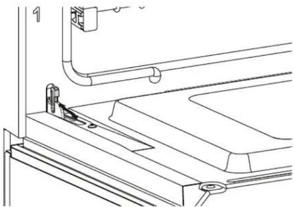
Removing the oven door
- Open the door fully. Flip the hinge clips down for both sides of the door. A screwdriver may be required to carefully pry the clip back.
natural_image
Technical line drawing of a mechanical assembly with pipes and supports (no text or symbols)-
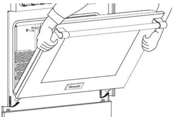
Close the door gently until it stops against the hinge clips. The open hinge clips will hold the door open at a slight angle, about 30^ , from the closed position.
-
Grasp the door firmly on the ends of the door. Lift the door up and out. There will be some spring resistance to overcome.
natural_image
Line drawing of hands installing or adjusting a door panel inside an oven (no text or symbols)- Place the door in a safe and stable location.
Reinstalling the oven door before leak testing the broil and bake burners
After replacing the bake burner orifices and the appliance satisfactorily gas leak tested, the oven door, kick panel, and the bottom front panel must be reinstalled.
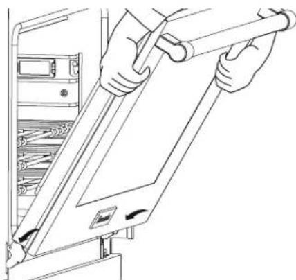
- Hold the door firmly in both hands.
- Hold the door at a 30° angle from the closed position. Insert hinges centered evenly into the hinge slots. The hinges will securely hook into the slots when properly installed. DO NOT force, bend or twist the door.
natural_image
Line drawing of hands installing a cable or cable component into a server rack (no text or symbols)-
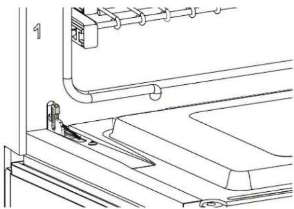
Open door fully to expose hinges, levers, and slots.
-
Flip the hinge forward until seated on the bracket. A screwdriver may be required to carefully push the clip back.
natural_image
Technical line drawing of a mechanical assembly with pipes and components (no text or symbols)- Close and open the door slowly to ensure it is correctly and securely in place.
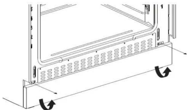
Removing the kick and front panels
- Remove the kick panel screws using a T-20 star-head screwdriver.
natural_image
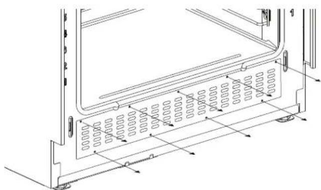
Technical line drawing of a mechanical component with internal channels and directional arrows (no text or symbols)- Remove the front panel screws using a T-20 star-head screwdriver.
natural_image
Technical line drawing of a mechanical component with internal spring-like structure and dimension arrows (no text or symbols)Changing the bake orifice, on GAS ranges only (PRG models)
Changing the main oven bake burner orifice
IMPORTANT:
- Do not bend the bake burner tube.
- Do not bend the bake burner gas tube.
- The bake burner air shutter should remain fully open. If the air shutter is not fully open, loosen the shutter screw and adjust it to the position shown. Re-tighten the screw to secure the shutter.
natural_image
Line drawing of a vehicle's side profile showing dashboard, seat, and dashboard frame (no text or symbols)- Do not remove the anti-rotation bracket when performing the orifice change. This bracket is critical to the alignment of the bake burner tube with the burner orifice. After the orifice replacement, this bracket will facilitate the burner tube's realignment.
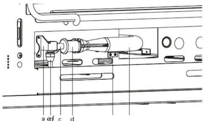
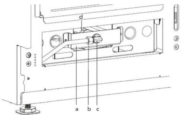
text_image
a e f c d| a. Anti-rotation bracket b. Bake gas line | |
| c. Elbow fitting d. Shutter | |
| e. Bake burner tube mounting bracket | f. Bake burner tube |
- Remove the bake gas line using a 13/16" box end wrench.
- Remove the two screws from the bake burner tube mounting bracket with a T-20 star-head driver.
natural_image
Illustration of hands using a tool to adjust or install a component (no text or symbols visible)-
Insert a 1/2" offset wrench into the shutter opening to restrain the bake orifice while hand twisting the orifice elbow counterclockwise.
-
Replace the orifice as indicated in the table.
Pro Grand
| Model Main oven bake | |
| All models 1.46 mm (1) | 46) |
Pro Harmony
| Model Main oven bake | |
| All models 1.34 (134) | |
- Ensure that the bake orifice is aligned to the center of the burner tube inlet. Reinstall the bake burner tube beneath the oven. If necessary, use a flashlight to aid in seeing the locating slot where the burner tube sits at the backside of the burner cavity.
- Slide the elbow fitting back into the anti-rotation bracket. Reattach the two bake burner mounting bracket screws and tighten the gas line.
- If the gas range is a single oven, perform a gas leakage check of the orifice and associated supply tube fittings per "Checking for gas leaks" on page 19. If the gas range has an auxiliary oven, proceed with the following instructions.
Changing the auxiliary oven bake burner orifice
text_image
d a b c| a. Auxiliary bake burner mounting bracket | b. Aux oven bake gas line |
| c. Elbow fitting d. Bake burner tube | |
IMPORTANT:
- Do not bend the bake burner tube.
- Do not bend the bake burner gas tube.
- The bake burner air shutter should remain fully open. If the air shutter is not fully open, loosen the shutter screw and adjust it to the position shown. Re-tighten the screw to secure the shutter.
natural_image
Line drawing of a vehicle rear seat and side panel (no text or symbols)- Remove the two screws from the auxiliary bake burner mounting bracket with a T-20 star-head driver. Pull the bracket and gas line carefully towards you.
NOTE: It is not necessary to loosen the auxiliary oven bake gas line.
- With an adjustable wrench, restrain the elbow fitting. With a 1/2" offset wrench, unscrew the auxiliary bake burner orifice.
For your convenience, note the orifice sizes and locations in the following table.
| Main oven bake Aux | oven bake |
- Replace the orifice as indicated in the table
Pro Grand
| Models Auxiliary | oven bake |
| All models 1.13 mm (113) |
Pro Harmony
| Model Aux oven | bake |
| 30'' — | |
| 36'' — | |
| 48'' 4 & 6-burners | 1.17 (117) |
NOTE: The replacement bake orifices have straight threads (not tapered threads) and DO NOT require thread sealing compound.
- Before reattaching the auxiliary bake burner mounting bracket, perform a gas leakage check of the orifice and associated supply tube fittings per "Checking for gas leaks" on page 19.
Checking for gas leaks
⚠ WARNING
DO NOT use a flame of any kind to check for gas leaks.
CAUTION
DO NOT spray water solution onto exposed electrical components. If solution does drip onto electrical components, shut the power off before wiping off the electronics.
CAUTION
Ensure that the STAR burner igniter wire terminals do not touch the chassis metal, or any metal part, to prevent sparking. Do not touch the igniter wires while the burner is turned on to avoid being shocked.
Leak testing should occur after the orifices are replaced and before the appliance is fully reassembled. However, the doors of the appliance must also be installed and closed in order to leak check the broil and bake burners.
Leak testing of the appliance shall be conducted according to the following instructions.
Gas leak checking the rangetop STAR® burners
- Make sure that the orifices have been tightened and that all valves and controls are in the OFF position.
- Turn on electric and gas supplies.
- Spray a generous amount of soap and water mixture—or other solution designed for checking gas leaks—on the threaded junction at the base of the orifice, the elbow fitting, and gas tube compression nut. (A 25% dishwashing liquid to water mixture is effective for this.) Avoid spraying electrical components.
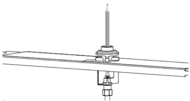
- Turn the corresponding STAR burner knob to HI while firmly blocking the STAR burner's orifice hole with a soft rubber pencil eraser, your finger, or something similar.
natural_image
Technical line drawing of a mechanical assembly with a central rod and mounting bracket (no text or symbols)- Monitor the base of the orifice junction, elbow fitting, and compression nut to see if bubbles are forming anywhere around the connections.
- Bubbles forming are indications of gas leaks.
- If appliance leaks, repair all gas leaks immediately. Do not over-torque the junctions, orifices or nuts, or bend the gas tubes. Repeat for all STAR burners.
Gas leak checking the broil orifice(s)
- Spray a generous amount of soap and water mixture—or other solution designed for checking gas leaks—on the threaded junction at the base of the orifice, the elbow fitting, and gas tube compression nut. (A 25% dishwashing liquid to water mixture is effective for this.) Avoid spraying electrical components.
- Turn the mode knob and the oven temperature knob to BROIL while blocking the broil orifice hole with a soft pencil eraser, your finger, or something similar.
- There will be a delay of approximately 45 to 90 seconds as the safety valve coil heats to release the valve's actuator. A single pop noise can usually be heard as the broiler's safety valve opens.
- Monitor the base of the orifice junction, elbow fitting, and compression nut to see if bubbles are forming anywhere around the connections.
- Bubbles forming are indications of gas leaks.
- If appliance leaks, repair all gas leaks immediately. Do not over-torque the junctions, orifices or nuts, or bend the gas tubes.
- If applicable, repeat for the auxiliary broil orifice.
Gas leak checking the bake orifice(s)
- Spray a generous amount of soap and water mixture—or other solution designed for checking gas leaks—on the threaded junction at the base of the orifice, the elbow fitting, and gas tube compression nut. (A 25% dishwashing liquid to water mixture is effective for this.) Avoid spraying electrical components.
- Turn the mode knob to BAKE and the oven temperature knob to any setting while blocking the bake orifice hole with your finger.
- There will be a delay of approximately 45 to 90 seconds as the safety valve coil heats to release the valve's actuator. A single pop noise can usual be heard as the broiler's safety valve opens.
- Monitor the base of the orifice junction, elbow fitting, and compression nut to see if bubbles are forming anywhere around the connections.
-
Bubbles forming are indications of gas leaks.
-
If appliance leaks, repair all gas leaks immediately. Do not over-torque the junctions, orifices or nuts, or bend the gas tubes.
-
If applicable, repeat for the auxiliary bake orifice.
- If the appliance has been satisfactorily leak checked, turn off the gas and electric supplies. Reinstall the auxiliary bake burner mounting bracket, if applicable, and continue to "Checking the flame and burner performance".
Checking the flame and burner performance
Checking the STAR ^® burner performance
⚠ WARNING
When cooking with the STAR burners, the burner flame size should be adjusted so it does not extend beyond the edge of the cooking utensil. This instruction is based on safety considerations.
To observe the burner flames, it may be necessary to turn off lights or close window blinds to darken the room for easier viewing of the flame.
Reassemble the rangetop as follows:
text_image
a. Grate b. Burner cap c. Venturi d. Burner base e. Electrode f. Burner pedestal g. Spill tray h. Heat shield i. Igniter housing j. Igniter wireTIP: Use the burner venturi as a centering guide when remounting the burner pedestals. If the pedestals are centered, the venturi will slide in and out easily after the T-30 star-head screw has been secured. If the pedestals are not centered properly, loosen the mounting screw and recenter the burner until the venturi slides freely.
Checking the STAR ^® burner ignition and flame
- Push in the burner control knob and turn it to HI.
- The igniter electrode and spark module will produce a clicking sound. Once the air has been purged from the supply lines, the burner should light within four seconds.
- The flames should be stable, with no excessive noise. The inner cones of the individual flames should be defined and separate from each other. Portions of the flame, along the burner, should not exhibit excessive or continuous indications of "lifting" or "lazy flame".
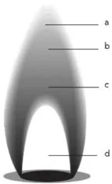
text_image
a b c d| a. Dark blue |
| b. Secondary cone |
| c. Light blue |
| d. Primary cone |
NOTE: It is normal for slight yellow tipping of the flames to appear after a few minutes of operation using Propane (LP) gas. Orange-colored streaks in the flame are produced from burning airborne debris; this is normal during initial start up and should dissipate within a few minutes of operation.
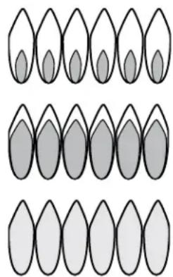
Yellow flames:
Further adjustment is required.
Yellow tips on outer cones:
Normal for LP gas
Soft blue flames:
Normal for natural gas
natural_image
Three rows of stylized leaf-like shapes with varying shades of gray, arranged in a row (no text or symbols)-
Adjust the burner's control valve to LO to see that the flame continues to wrap around the burner. Blow out the flame, or use a quick fan motion from a writing tablet or piece of cardboard to extinguish the flame. Observe the burner's ability to reignite and wrap around (also called "carry-over") the burner within several seconds. This flame "carry-over" is essential for proper burner ignition and re-ignition.
-
Test re-ignition of the XLO ^® and observe the carry-over of the small simmer flames as the XLO system cycles the burners on and off.
- If the low flame performance is not acceptable, it may be necessary to readjust the valve screw for a STAR burner that does not have sufficient carry-over of the low flame. Turn the valve screw slightly counter-clockwise until carry-over of the flame is acceptable. (See "Setting the STAR® burner valve screws" on page 21.)
- If the burner flame is uneven, flutters, makes excessive noise, or lifts, some of the slots in the burner base may be blocked with food spillage or other debris.
- Clogged slots can be cleared using a straightened paper clip, needle, or similar object. Encrusted food or debris can sometimes be removed using a steel wool pad or fine wire brush.
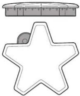
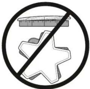
- Burner flames that are "lazy", with excessively-long flames, can be created by an incorrectly fitted burner cap—from which many of the outer mantles of the individual flames will tend to "coalesce" or blend together. Verify that the burner cap is seated properly on its burner base. The cap should fit reasonably flat when correctly-positioned on the base and not rock significantly.
natural_image
Two simple line drawings: a circular ruler above a star-shaped outline and a square ruler below it (no text or symbols)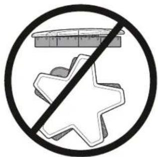
text_image
Prohibition sign with crossed-out shapes and a ruler above, symbolizing food safety or nutrition.Correct burner cap Incorrect burner cap
- Repeat the ignition and flame test procedures for each rangetop STAR burner.
Setting the STAR® burner valve screws
A flat-head screwdriver with a 2.5 mm wide tip (included) is used to adjust the valve screws.
To set the burner valve screws
- Turn the knob counterclockwise.
- Standard burners: Turn a full turn until knob cannot be turned anymore.
• XLO burners: Turn to LOW.
-
Remove the knob from the valve stem by slowly pulling knob straight out, away from the control panel.
-
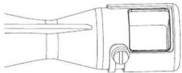
To set the burner valve screws on all models except 8-burner models:
Remove the bezel-mounting screw located to the right of the valve stem using a T-20 star-head screwdriver. Insert the included flat-blade screwdriver into the hole of the bezel mounting screw.

natural_image
Diagram of a mechanical component with a conical tip and circular housing (no text or symbols)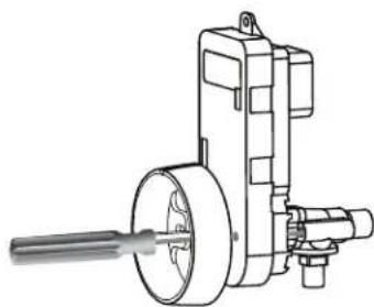
natural_image
Technical line drawing of a mechanical device with shaft and housing (no text or symbols)To set the burner valve screws on 8-burner models:
Insert the included flat-blade screwdriver into the hole of the valve stem. The removal of the bezel screw is not required.
natural_image
Technical line drawing of a mechanical assembly with rollers and linkages (no text or symbols)-
Access to the valve screws through the clearance hole in the spark module. You should feel the engagement of the screwdriver and the valve screw.
-
Adjust the valve screw by turning the valve screw about an 1/8^th turn. Turn the screw clockwise to reduce simmer flame size. Turn the screw counterclockwise to make the simmer flame larger. Adjust the valve screw as little as required to reach satisfactory simmer results. Adjustments should be done after the range has been fully converted. Due to normal fluctuations in gas pressure, over-adjustment of valve screw may affect flame stability.
Checking the gas broil ignition and flame (gas range only)
NOTE: The oven door(s) must be installed and closed.
-
Turn on the main oven mode knob and the oven temperature knob to BROIL.
-
The hot-surface igniter will attempt to light the broiler after approximately 45 to 90 seconds, as the safety valve coil heats to open. Once the air has been purged from the gas supply line, the broiler should light within four (4) seconds.
- Observe the broil flame performance through the oven door window. The ceramic tiles of the burner should glow red hot (infrared) after several minutes of operation. If after several minutes with the burner lit, the broiler only has a small amount of red glow (and burns mostly with blue flame floating on the burner surface), check that the broiler orifice is aligned to the center of the burner tube inlet.
- Repeat for the auxiliary oven, if applicable.
- If the broil burner burns satisfactorily, reassemble the backguard onto the appliance (see page 15).
Checking the gas bake ignition and flame (gas range only)
NOTE: The oven door(s) must be installed and closed.
- Install the front panel (see page 16).
- Turn the main oven mode knob to BAKE and the oven temperature knob to any setting.
- The hot-surface igniter will attempt to light the burner tube after approximately 45 to 90 seconds, as the safety valve coil heats to open. Once the air has been purged from the gas supply line, the burner should light within four (4) seconds.
- Observe the bake burner flame through the slots in the bottom front panel. Look for considerable "yellow tipping," noting that some small amount of yellow tipping is normal in the flame characteristics of burners running with propane (LP) gas, flame lifting, or lazy flames.
- Repeat for the auxiliary oven, if applicable.
- If the bake burner burners perform satisfactorily, reinstall the kick panel (see page 16).
Placing the conversion label
- For proper identification and evidence of the appliance's conversion for propane (LP) gas operation, affix the provided conversion label in a location next to the rating labels on the appliance.
Pro Grand conversion label placement
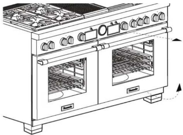
natural_image
Line drawing of a two-wheeled kitchen oven with doors and heat sinks (no text or symbols)Pro Harmony conversion label placement
text_image
MensakePro Rangetop conversion label placement
natural_image
Line drawing of a gas stove with multiple panes and side grilles (no text or symbols)-
Use a permanent marker to fill-in the date, name, and address of your service organization on the conversion label.
-
Review the "Checklist" on page 7 to ensure that all steps have been completed.
-
Leave this installation manual and all removed parts with the owner of the appliance for future use or for converting the unit back to natural gas.
Table des matières
6696 Financial Drive, Unit 3
Mississauga, ON L5N 7J6
Des questions?
1-800-735-4328
www.thermador.com ou www.thermador.ca
natural_image
Technical line drawing of a mechanical assembly with two internal components and directional arrows indicating motion (no text or symbols)text_image
Technical diagram showing a mechanical device with labeled parts (a, b) and directional arrows indicating motion or assembly.natural_image
Line drawing of a hand gripping a mechanical component (no text or symbols)text_image
Technical diagram showing mechanical assembly with labeled parts a, b, and ca. Ressort
text_image
a b d7 NATa. Gaz naturel b. Gaz de PL
text_image
Technical diagram showing two-step assembly of a screwdriver tool, with labeled parts and directional arrows indicating process flow.text_image
Technical diagram showing a hand using a screwdriver to adjust a component, with an inset image of a light bulb being inserted.natural_image
Symmetrical geometric pattern with four numbered star-like shapes arranged in a grid (no text or symbols)| (1) 105 (3) 105 | |
| (2) 115 (4) 115 |
Modèle 305
flowchart
graph TD
    A["1"] --> B["2"]
    B --> C["3"]
    C --> D["4"]
    D --> E["5"]
natural_image
Three identical geometric star patterns arranged in a 2x2 grid, no text or symbols present.| (1) 105 (3) 105 (5) 105 | ||||
| (2) | 115 | (4) | 115 | (6) |
natural_image
Three identical geometric panels with six star-shaped patterns arranged in a grid (no text or symbols)| (1) 105 (3) 105 (5) 105 | |
| (2) 126 (4) 115 (6) 115 |
natural_image
Pure architectural or mechanical diagram showing symmetrical star-shaped panels and a door, without any text, numbers, or symbols.| (1) 105 (3) 105 | (5)— | |
| (2) 126 (4) 115 |
natural_image
Diagram of a three-panel window with star patterns and a door, no text or symbols present| (1) 105 (3) 105 (5) 105 | (7)— | |
| (2) 126 (4) 115 (6) 115 |
text_image
Architectural elevation drawing of a double door with star-shaped panels and numbered compartments| (1) 105 (3) 105 (5)—(7) 105 | ||
| (2) 126 (4) 115 (6)—(8) 115 |
natural_image
Architectural elevation drawing of a traditional Chinese-style window with star-shaped panels and a central door (no text or symbols)| (1) 105 (3) 105 | (5)— | (6) 105 |
| (2) 126 (4) 115 (7) 115 |
natural_image
Technical line drawing of a mechanical assembly with two components and mounting brackets (no text or symbols)natural_image
Pure structural diagram of a beam supported by vertical supports, showing load directions (no text or symbols)natural_image
Technical diagram of a mechanical switch mechanism with no visible text or symbolsnatural_image
Technical line drawing of a mechanical assembly with pipes and mounting brackets (no text or symbols)natural_image
Line drawing of hands installing or adjusting a door panel inside an oven (no text or symbols)natural_image
Line drawing of hands installing or adjusting a mechanical component into a server rack (no text or symbols visible)natural_image
Technical line drawing of a mechanical assembly with pipes and components (no text or symbols)natural_image
Technical line drawing of a mechanical component with internal channels and directional arrows (no text or symbols)natural_image
Technical line drawing of a mechanical component with internal spring-like structure and dimension arrows (no text or symbols)natural_image
Line drawing of a vehicle interior with no text or symbolsnatural_image
Illustration of hands using a tool to adjust or install a component, no text or symbols presentnatural_image
Line drawing of a vehicle's side profile showing front, rear, and side panels (no text or symbols)natural_image
Technical line drawing of a mechanical assembly with a central pin and mounting bracket (no text or symbols)natural_image
Two simple line drawings: a ruler and a five-pointed star outline (no text or symbols)text_image
Prohibition sign with crossed-out star and ruler above, symbolizing food safety or nutritionnatural_image
Diagram of a circular mechanical component with a pointed tip and a conical tip, no text or symbols present.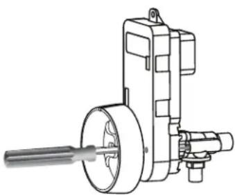
natural_image
Technical line drawing of a mechanical pump assembly (no text or symbols)natural_image
Technical line drawing of a mechanical assembly with rollers and linkages (no text or symbols)natural_image
Line drawing of a two-wheeled kitchen oven with doors and heat sinks (no text or symbols)text_image
Technical line drawing of a microwave oven with labeled control panel and directional arrows indicating rotationnatural_image
Line drawing of a gas stove with multiple panes and control knobs (no text or symbols)natural_image
Technical line drawing of a mechanical assembly with two internal components and directional arrows indicating motion (no text or symbols)text_image
Technical diagram showing a tool interacting with a star-shaped mechanical component, labeled with parts a and b and directional arrows.a. Cabeza hexagonal b. Venturi
natural_image
Line drawing of a wrench gripping a mechanical component (no text or symbols)text_image
Technical diagram showing mechanical assembly with labeled parts a, b, and ctext_image
a b d7 NATa. Gas natural b. Gas LP
text_image
Diagram illustrating screwdriver tool installation steps with labeled parts 1 and 2natural_image
Technical line drawing of a hand using a screwdriver to adjust or install a mechanical component (no text or symbols present)natural_image
Symmetrical geometric pattern with four numbered star-like shapes arranged in a grid (no text or symbols)| (1) 105 (3) 105 | |
| (2) 115 (4) 115 |
Modelo 305
flowchart
graph TD
    A["1"] --> B["2"]
    B --> C["3"]
    C --> D["4"]
    D --> E["5"]
natural_image
Pure electrical circuit lines without any symbols| (1) 105 (3) 105 | (5)— | |
| (2) 126 (4) 115 |
text_image
Diagram of a multi-panel architectural or mechanical layout with numbered star-shaped elements and a central grid pattern.| (1) 105 (3) 105 | (5)— | (6) 105 | |
| (2) 126 (4) 115 (7) 115 |
natural_image
Architectural floor plan showing three window-like furniture units with star patterns and a central door (no text or symbols)| (1) 105 (3) 105 (5)— | (7) 105 | ||
| (2) 126 (4) 115 (6)— | (8) 115 |
natural_image
Architectural floor plan showing three front panels with star-shaped decorative elements and a central circular object (no text or symbols)| (1) 105 (3) 105 | (5)— | (6) 105 | |
| (2) 126 (4) 115 (7) | 115 |
natural_image
Technical line drawing of a mechanical assembly with two components and directional arrows indicating movement (no text or symbols)natural_image
Pure structural diagram of a beam supported by vertical supports, showing load directions and support points (no text or symbols)natural_image
Technical diagram of a mechanical assembly with an adjustable wrench and rotating component (no text or symbols)natural_image
Technical line drawing of a mechanical assembly with pipes and mounting brackets (no text or symbols)natural_image
Line drawing of hands installing or adjusting a door panel inside a microwave oven (no text or symbols)natural_image
Line drawing of hands installing or adjusting a mechanical component on a server rack (no text or symbols visible)natural_image
Technical line drawing of a mechanical assembly with pipes and components (no text or symbols)natural_image
Technical line drawing of a mechanical component with internal channels and directional arrows (no text or symbols)natural_image
Technical line drawing of a mechanical component with internal spring-like structure and dimension arrows (no text or symbols)natural_image
Illustration of hands using a tool to adjust or install a component (no text or symbols visible)natural_image
Line drawing of a vehicle cabin interior with handle and seat (no text or symbols)natural_image
Technical line drawing of a mechanical assembly with a central rod and flange (no text or symbols)natural_image
Two simple line drawings: a top row of a ruler and a five-pointed star outline (no text or symbols)Tapa del quemador correcta
text_image
Prohibition sign with crossed-out shapes and a ruler above, indicating no text or symbols beyond basic geometry.Tapa del quemador incorrecta
natural_image
Diagram of a circular device with internal components and a funnel pointer (no text or symbols)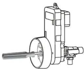
natural_image
Technical line drawing of a mechanical device with shaft and housing (no text or symbols)natural_image
Technical line drawing of a mechanical assembly with rollers and linkages (no text or symbols)natural_image
Line drawing of a two-wheeled kitchen oven with heat sinks and fan dividers (no text or symbols)text_image
Technical line drawing of a double boiler with labeled control panel and directional arrows indicating rotation or movement.natural_image
Line drawing of a gas stove with multiple panes and heat sinks (no text or symbols)Thank you for being a Thermador customer!
USA:
Thermador is dedicated to supporting you and your appliance so you have many years of creative cooking. Please don't hesitate to contact us if you have any questions. We're happy to help you with cleaning and care instructions, cooking tips, accessories, troubleshooting, scheduling service visits, and more.
1-800-735-4328
www.thermador.com/us/support/customer-care
Canada:
1-800-735-4328
www.thermador.ca/en/support/customer-care
Accessories and parts
USA:
Filters, Thermador cleaners, teppanyaki pans, griddles, replacement parts, and more can be purchased in our online accessories store.
www.thermador.com/us/accessories
Canada:
Visit the webpage below to learn how to purchase filters, cleaners, accessories and parts.
www.thermador.ca/en/support/filters-cleaners-accessories
Soutien
www.thermador.com/us/support/customer-care
Canada :
1-800-735-4328
www.thermador.com/us/accessories
Canada :
www.thermador.com/us/support/customer-care
Canadá:
1-800-735-4328
www.thermador.ca/en/support/filters-cleaners-accessories
Accesorios y piezas
EEUU:
www.thermador.com/us/accessories
Canadá:
www.thermador.ca/en/support/filters-cleaners-accessories