PA60WLBG - Oven THERMADOR - Free user manual and instructions
Find the device manual for free PA60WLBG THERMADOR in PDF.

User questions about PA60WLBG THERMADOR
0 question about this device. Answer the ones you know or ask your own.
Ask a new question about this device
Download the instructions for your Oven in PDF format for free! Find your manual PA60WLBG - THERMADOR and take your electronic device back in hand. On this page are published all the documents necessary for the use of your device. PA60WLBG by THERMADOR.
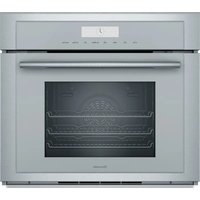
USER MANUAL PA60WLBG THERMADOR
Professional Series Pro Grand® Range Low Backguard and Toe Kick Accessory
natural_image
Black-and-white photo of a plated seafood dish featuring whole fish, lemon slices, and garnishes (no text or symbols visible)Installation
INSTRUCTIONS
Professional Series Pro Grand ^® Range Low Backguard and Toe Kick Accessory
English....2
Français ....5
Español....8
Models |
Modèles |
Modelos:
PA36JLBG
PA48JLBG
PA48JLBSG
PA60RLBG
PA36JTKG
PA48JTKG
PA60RTKG
Safety
DEFINITIONS

WARNING
This indicates that death or serious injuries may occur as a result of non-observance of this warning.

CAUTION
This indicates that minor or moderate injuries may occur as a result of non-observance of this warning.
NOTICE: This indicates that damage to the appliance or property may occur as a result of non-compliance with this advisory.
Note: This alerts you to important information and/or tips.
Rear clearance
REQUIREMENTS
- To avoid staining on the back wall, high temperature, non-porous construction materials suitable for use in a cooking environment are recommended.
- Models PRD606xx are suitable for 0" rear clearance to combustible surfaces.
-
All other models:
-
When using the included island trim a minimum 6" (152 mm)* rear clearance is required to a combustible surface*.
- When installing against a combustible surface, a Thermador low backguard is required for a 0" rear clearance to the combustible surface. A Thermador low backguard must be purchased separately.
- A rear clearance to a surface covered in a non-combustible material (metal, ceramic tile, brick, marble, or stone) ^* is 0'' when using the included Island Trim.
*Clearances of less than 6" (152 mm) should be approved by the local codes and/or by the local authority having jurisdiction.
Δ Clearances from non-combustible materials are not part of the ANSI Z21.1 scope and are not certified by CSA.
Installation
INSTRUCTIONS
For use with the following models:
PRD364WDGx PRD48WCSGx PRG364WDG
PRD364WIGx PRD48WDSGx PRG364WLG
PRD364WLGx PRD48WISGx PRG366WG
PRD366WGx PRD48WLSGx PRG486WDG
PRD484WCGx PRD606WCG PRG486WLG
PRD486WDGx PRD606WCSG
PRD486WIGx PRD606WEG
PRD486WLGU PRD606WESG
State of California Proposition 65 Warning:
⚠ WARNING
This product can expose you to chemicals including vinyl chloride, which is known to the State of California to cause cancer and birth defects or other reproductive harm. For more information go to www.P65Warnings.ca.gov.
WARNING
Fingers or hands could get pinched when installing the backguard. Severe injury could result. Use extreme caution and wear thick protective gloves to avoid potential laceration to finger or hand while sliding the backguard down onto the range.
WARNING
To avoid possible burn or fire hazard, a backguard designed specifically for this appliance must be installed whenever the appliance is used.
Low backguard installation
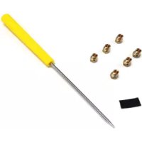
Tools needed
• T-20 torx head screwdriver or drill
• Protective work gloves
Attach the backguard before sliding the appliance into the final installed position.
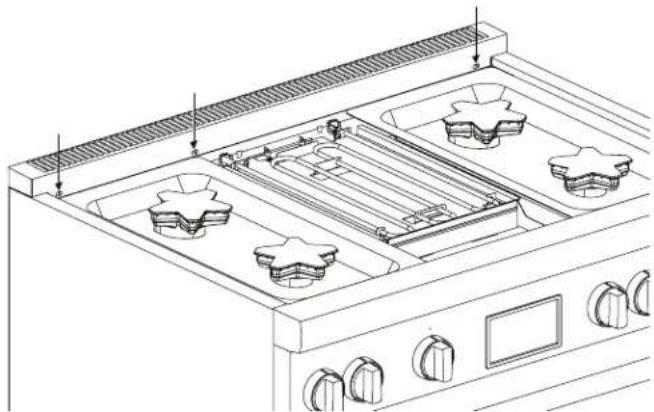
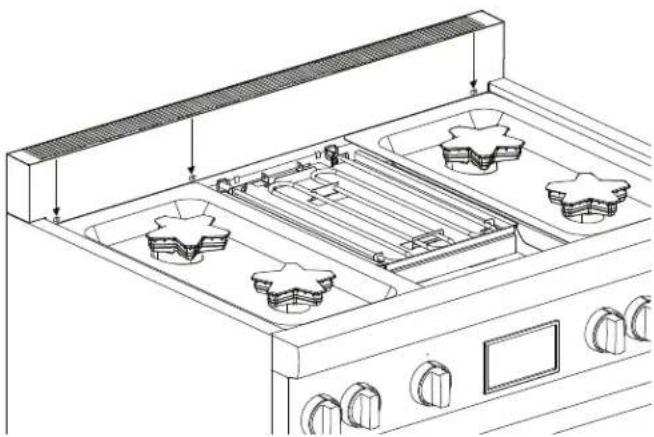
To remove the island trim
- With a T-20 torx head screwdriver, remove the screws in the front face of the island trim.
natural_image
Line drawing of a kitchen stove interior with three star-shaped grilles and control knobs (no text or labels)- Remove the T-20 torx screws securing the trim to the side panels and the back panel. Lift up to fully remove.
natural_image
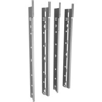
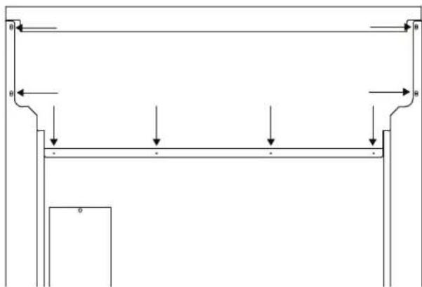
Pure structural diagram of a beam supported by vertical supports, showing load directions (no text or symbols)To install the low backguard
- Align the low backguard with the range side panel's right and left rear corners. The backguard is inserted inside the guide channels on the back of the range.

natural_image
Technical line drawing of a mechanical assembly with no visible text or symbols- The backguard's front face is outside the flange on the front side of the range.
natural_image
Line drawing of a kitchen stove interior with four star-shaped appliances and control knobs (no text or labels)- Re-install screws.
Toe kick panel installation
Tools needed
- Protective work gloves
To remove the front foot cover assemblies
- The mating part has dimples that seize the top piece of the foot cover. Spread the top cover out and slide it down to clear these dimples. Repeat for the other front foot cover assembly.
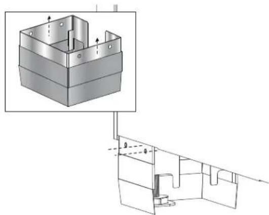
natural_image
Technical diagram showing a 3D mechanical assembly with an inset close-up of a component (no text or symbols present)- Remove the leg covers by sliding the top, outer sleeve of the leg covers off the extruded dimples of the base.
To install the toe kick panel
- Remove protective plastic covering from the toe kick panel.
- Remove the door trim from its mounting clips. (No tools required.)
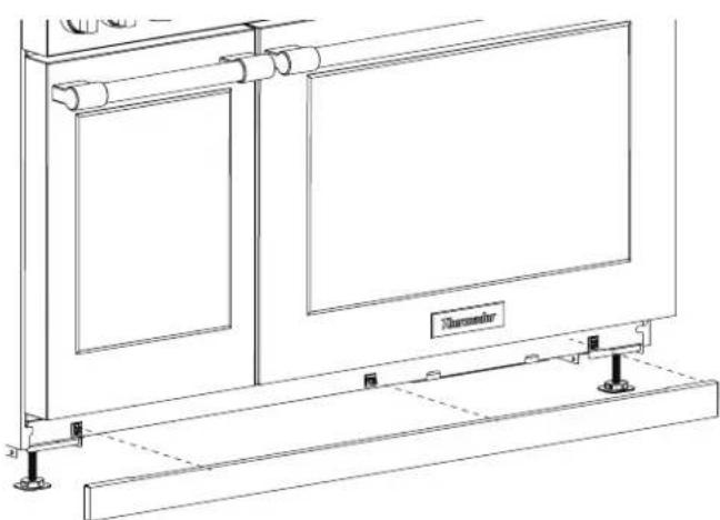
natural_image
Technical line drawing of a mechanical or electrical enclosure with mounting base and control panel (no text or symbols)- Press the toe kick panel into the mounting clips.
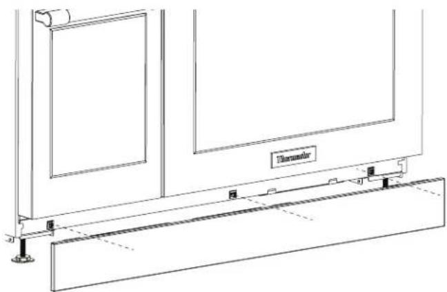
natural_image
Technical line drawing of a door frame assembly with mounting base and railings (no text or symbols)NOTE: The mating part has extruded dimples on both sides for which the holes of the toe kick panel should seize. You should feel a definitive snap, letting you know that the part has been installed.
natural_image
Line drawing of a kitchen stove interior with four grilles and a control panel (no text or symbols)natural_image
Pure mechanical assembly diagram showing a frame structure with arrows indicating force or movement (no text or symbols)natural_image
Technical line drawing of a mechanical assembly with no visible text or symbolsnatural_image
Line drawing of a kitchen stove interior with four star-shaped appliances and control knobs (no text or labels)natural_image
Technical diagram of a mechanical housing assembly with internal components and mounting features (no text or labels)natural_image
Technical line drawing of a heating element cabinet with cooling fins and mounting base (no text or symbols)natural_image
Technical line drawing of a door frame assembly with mounting base and railings (no text or symbols)natural_image
Line drawing of a kitchen stove with four panes and a grater (no text or symbols)natural_image
Pure structural diagram of a frame with supports and arrows, no text or symbols presentnatural_image
Technical line drawing of a mechanical assembly with no visible text or symbolsnatural_image
Line drawing of a kitchen oven with three star-shaped appliances and control knobs (no text or symbols)natural_image
Technical diagram showing a 3D mechanical assembly with an inset close-up of a layered component (no text or symbols present)natural_image
Technical line drawing of a heating element with cooling fins and mounting base (no text or symbols)natural_image
Technical line drawing of a door frame assembly with mounting base and railings (no text or symbols)Thank you for being a Thermador customer!
Thermador is dedicated to supporting you and your appliance so you have many years of creative cooking. Please don't hesitate to contact us if you have any questions. We're happy to help you with cleaning and care instructions, cooking tips, accessories, troubleshooting, and more.
USA:
1-800-735-4328
thermador.com/customer-care
Canada:
1-800-735-4328
thermador.ca/support
Accessories and parts
Filters, Thermador cleaners, teppanyaki pans, griddles, replacement parts, and more can be purchased in our online accessories store.
USA:
store.thermador.com/us
Canada:
Filters, parts and accessories can be purchased through our distributors.
Marcone: 1-800-287-1627
Reliable Parts: 1-800-663-6060
Soutien
thermador.ca/support
thermador.ca/support