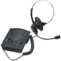
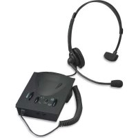
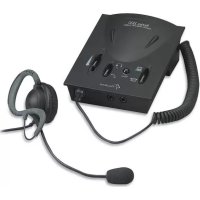
55251 - Headphones Compucessory - Free user manual and instructions
Find the device manual for free 55251 Compucessory in PDF.

| Product Type | Telephone and multimedia amplifier with headset |
| Brand | Compucessory |
| Model | 55251 |
| Power supply | 2 AA batteries (alkaline recommended) or 6-9 V DC power adapter (not included) |
| Nominal operating voltage | 3 V DC |
| Max operating current | 9 mA |
| Standby current | 200 mA |
| Speaker amplifier gain | 13 dB (max) |
| Standby mode activation | 2 to 3 minutes without signal |
| Phone connectivity | RJ-11 modular jack for handset and telephone headset |
| Computer connectivity | 3.5 mm stereo jack for line input and output |
| Headset connectivity | Separate RJ-11 (phone) or 3.5 mm jack (computer) for speaker and microphone |
| Main functions | Phone amplification, computer mode, volume control (receive and transmit), mute, phone/computer switch, headset/handset switch, 6-position configuration switch |
| Included accessories | Headset, RJ-11 telephone connection cable, computer audio cable (green and blue plugs), screwdriver pin |
| Compatibility | Works with most phones and computers (except phones with keypad in the handset) |
| Care and cleaning | Clean with a soft, dry cloth. Replace batteries if necessary. |
| Safety | Adjust volume gradually to avoid whistling and protect hearing. Use a power adapter with correct polarity. |
| Spare parts and repairability | Refer to Compucessory after-sales service. Batteries available commercially. |
| Standards | CE, US, FC |
| Dimensions (estimated) | Approximately 15 x 10 x 4 cm |
| Weight (estimated) | Approximately 200 g (without batteries) |
Frequently Asked Questions - 55251 Compucessory
User questions about 55251 Compucessory
0 question about this device. Answer the ones you know or ask your own.
Ask a new question about this device
Download the instructions for your Headphones in PDF format for free! Find your manual 55251 - Compucessory and take your electronic device back in hand. On this page are published all the documents necessary for the use of your device. 55251 by Compucessory.
USER MANUAL 55251 Compucessory
natural_image
White silhouette of a classic rotary telephone on a green background (no text or symbols)
natural_image
Simple line drawing of a laptop computer with no text or symbols
natural_image
Simple line drawing of a telephone handset (no text or symbols)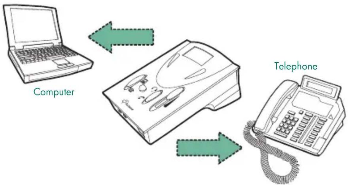
flowchart
graph TD
    A["Computer"] --> B["Telephone"]
    B --> C["Mobile Device"]
    C --> D["Computer"]
Thank you for purchasing a Compucessory Telephone & Multi-media Amplifier Kit. This unit is designed and developed with the aim to provide busy users, whether at home or in the office, the comfort and convenience of using telephone and computer with a single unit, freeing their hands for more important tasks. Compucessory amplifiers work with most retail and system telephones in the market, with the exception of telephones with the dial-pad inside the handset.
This guide will walk you through your basic installation and normal operations of a your Compucessory Amplifier:
PART I GETTING COMFORTABLE
I.1 Understanding the Controls.
1.2 Connection and Preparations.
1.2.1 connect to telephone
1.2.2 connect to computer
1.2.3 connect to headset
1.2.4 configure the control unit
1.3 Features and Functions
1.3.1 external DC supply (optional)
1.3.2 power on/off switch
1.3.3 rotary transmit volume control
1.3.4 telephone/computer application switch
1.3.5 headset/handset application switch
1.3.6 mute switch
1.3.7 slide reception volume control
PART II BEGIN TO OPERATE
II.1 Telephone Communication
II.1.1 receiving calls/making calls using headset
II.1.2 using headset with computer
II.2 Troubleshooting
PART III ACCESSORIES & SPECIFICATIONS
III.1 Accessories
III.2 Specifications
PART I GETTING COMFORTABLE
I.1 Understanding the Controls
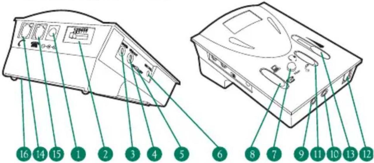
MAIN SWITCHES AND INTERFACE
- External DC Supply Jack (6V DC to 9V DC) – External Adapter NOT Included
- Telephone Configuration Switch
Jack (3.5mm diameter stereo) from Computer Line Out Jack (3.5mm diameter stereo) from Computer Line In - Power
Switch - Rotary Transmission
Control Switch Application Switch - Computer Headset Jack (3.5mm diameter stereo) from Speaker Plug
- Computer Headset Jack (3.5mm diameter stereo) from Microphone Plug
Application Switch - Modular Jack for
Headset - Slide Reception Volume Control
- Modular Jack for
Handset - Modular Jack for Input from Telephone Unit
- Battery Compartment Door – Uses two AA size batteries
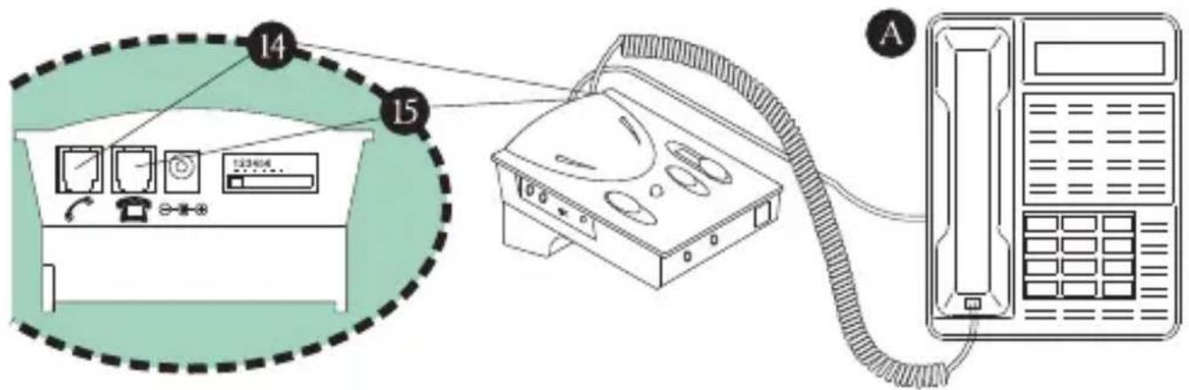
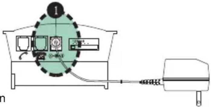
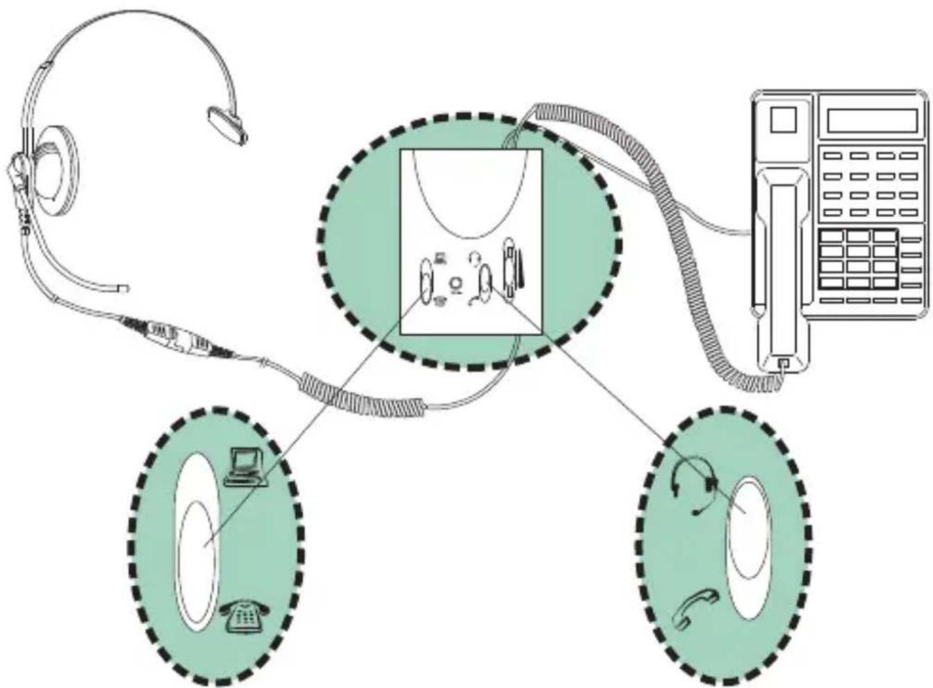
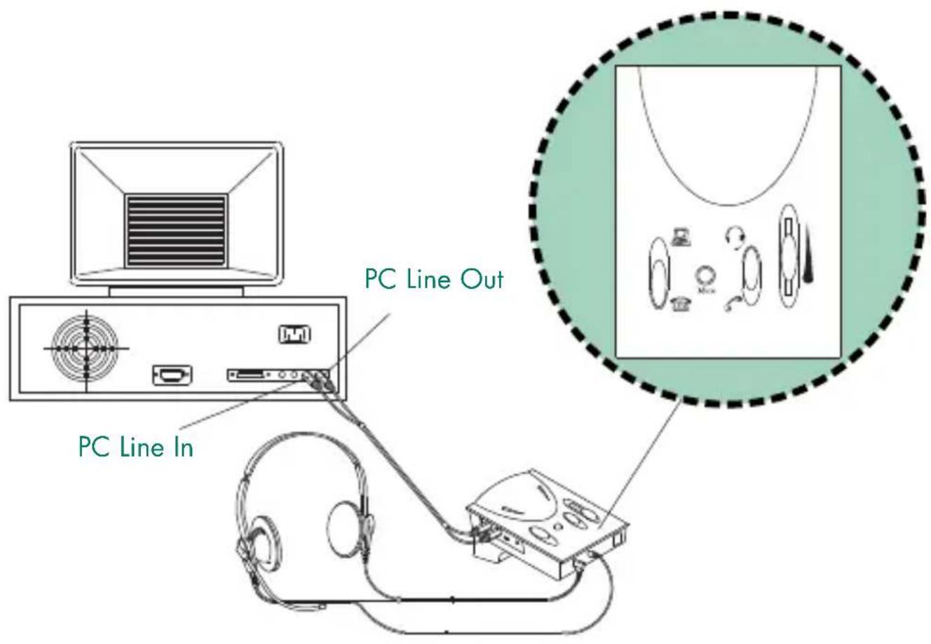
I.2.1 Connecting to Telephone
Unplug the handset from your telephone base unit and insert it to the Handset Modular Jack (14). Use the phone cord provided with RJ-11 modular plug on both ends to connect the control unit to your telephone. Plug one end of the cord to your base unit (A) and the other end to the Phone Input Modular Jack (15) on the back of the unit. (See illustration below)
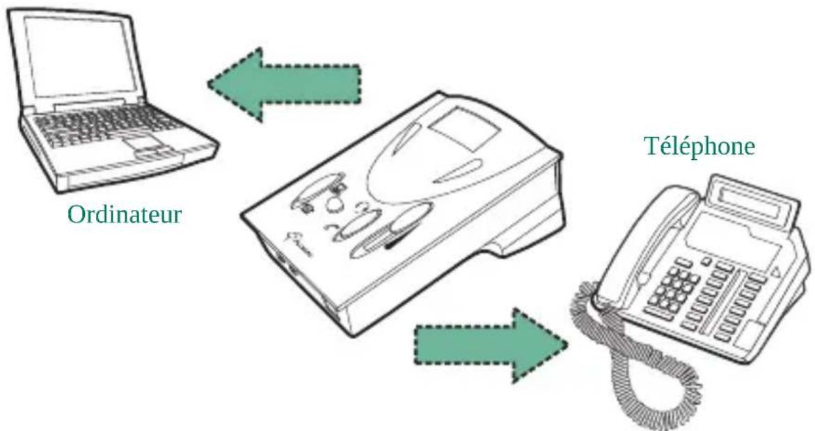
I.2.2 Connecting to Computer (not necessary when using with telephone only)
Connect this unit to your computer with the audio cable provided. The color of the plugs is already-color coded in accordance with the universal standard of line-in and line-out. In another words, the speaker output line is green, and the microphone input line is blue for the computer.
CONNECTING TO THE UNIT:
Green plug goes to "Line-In" Jack (also green)(3).
Blue plug goes to "Line-Out" Jack (also blue) (4).
CONNECTING TO THE COMPUTER SOUND CARD:
Green plug goes to "Line-Out" or "Speaker Out" Jack (also green).
Blue plug goes to "Line-In" Jack (also blue).
natural_image
Line drawing of a medical device with attached cable and connector (no text or symbols)1.2.3 Connecting to Headset
The amplifier provides the choice of using telephone headset (with RJ-11 Modular Plug) or stereo computer headset (with 3.5mm Diameter Plugs) according to your preference. For users who require stereo sound in their multimedia application, you can choose from our wide selection of our Compucessory computer head
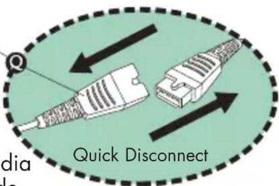
The headset included with the amplifier comes with a special-designed Quick Disconnector (Q), giving you convenience and compatibility.
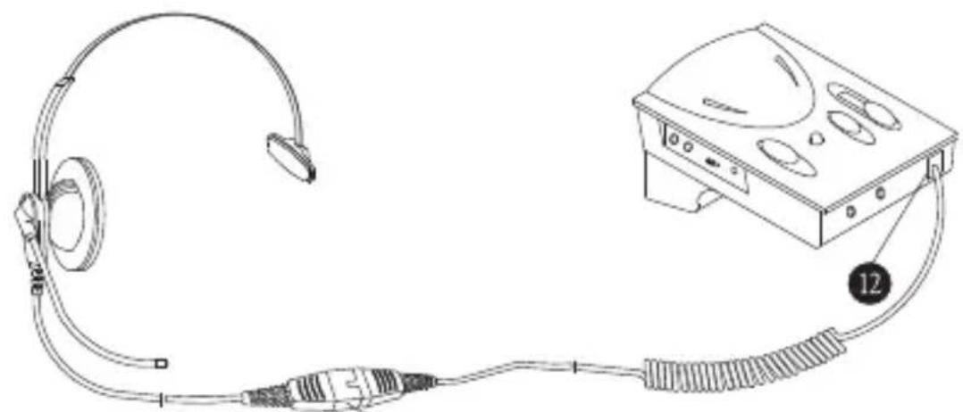
CONNECTING TO THE TELEPHONE HEADSET:
Plug in the telephone headset to the RJ-11 Modular Jack (12) on the front panel of the unit.
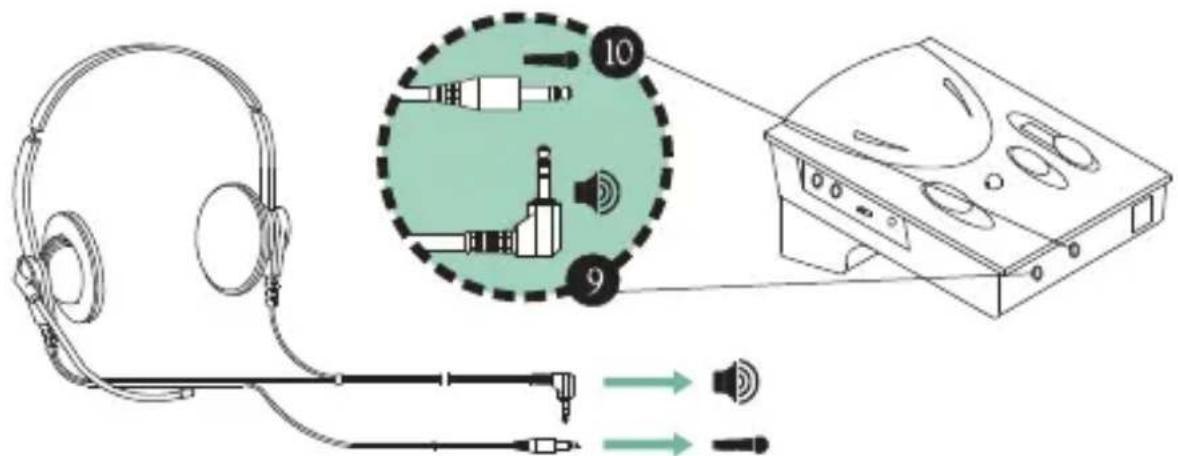
CONNECTING TO COMPUTER HEADSETS:
This applies only to computer headsets with separate microphone and speaker plugs. Insert the Speaker Plug of the headset to the Jack on the Front Panel with the "Speaker" sign (9) and the Microphone Plug to the Jack with the "Microphone" sign (10).
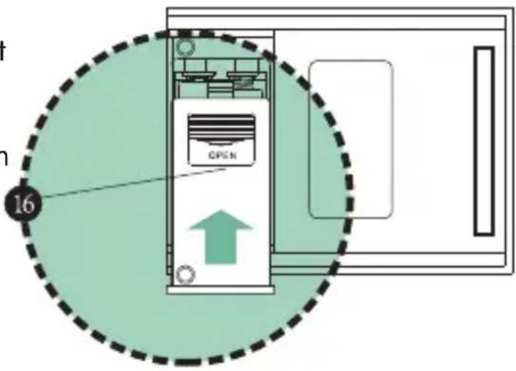
REPLACING BATTERIES:
Slightly depress the compartment lid and slide it outwards. Install batteries with polarities (+, -) according to the battery diagram inside the compartment. Close the lid and turn the power "ON". Two AA batteries are required. Alkaline batteries are recommended.
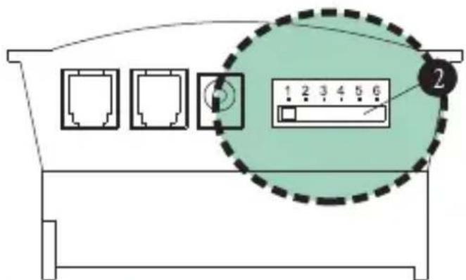
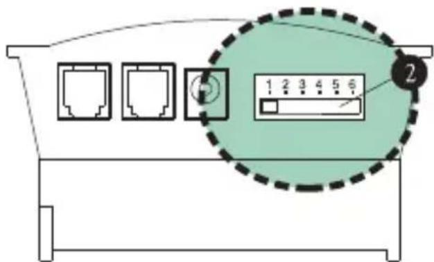
1.2.4 Configure the Control Unit
The 6-position Configuration Switch (2) at the back panel allows you to select the proper setting so that the unit will work with your telephone base unit. The control has 6 positions, which are (1 - 2 - 3 - 4 - 5 - 6). Wear the headset over your head and switch the Handset/Headset Switch (11) to the Headset position. Make sure to turn down the volume adjustment to protect your ear. Check to see if the Telephone/Computer Switch (8) is set to telephone position, if not, make sure it is. Now move the switch through positions 1-6 slowly until you can hear a clear dial tone.
If you receive a clear dial tone sound, then the receiving connection is working. Note that there may be 2 matching setting, choose the clearer setting or either one if both perform the same. There is at least one setting which matches your telephone.
flowchart
graph LR
    A["Step 8: Display panel"] --> B["Step 11: Circular component with arrows indicating rotation"]
    style A fill:#f9f,stroke:#333
    style B fill:#bbf,stroke:#333
I.3.1 External DC Supply Jack (1)
The unit provides the choice of using an optional external DC supply instead of batteries.
When purchasing an AC adapter, make sure the output polarity (+/- voltage) matches the unit.
And the voltage should be between 6V DC to 9V DC.
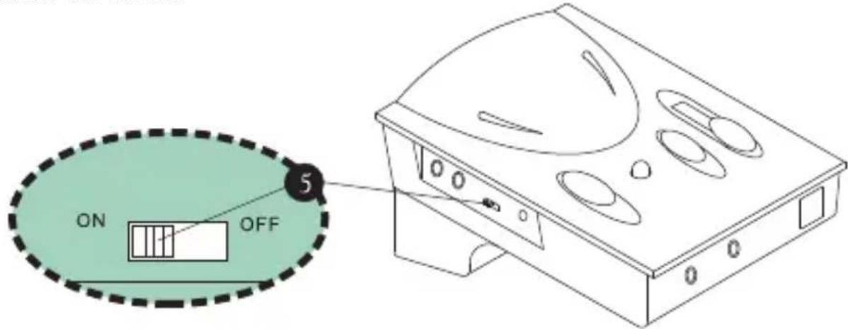
I.3.2 Power ON/OFF Switch (5)
Although the unit will return to standby mode automatically after each extended period of inactivity, you will still want to turn it off when not in use for a prolonged period of time to extend battery life. Turning off the unit does not affect normal telephone communication through the handset, so you can answer or make phone calls through the handset as usual.
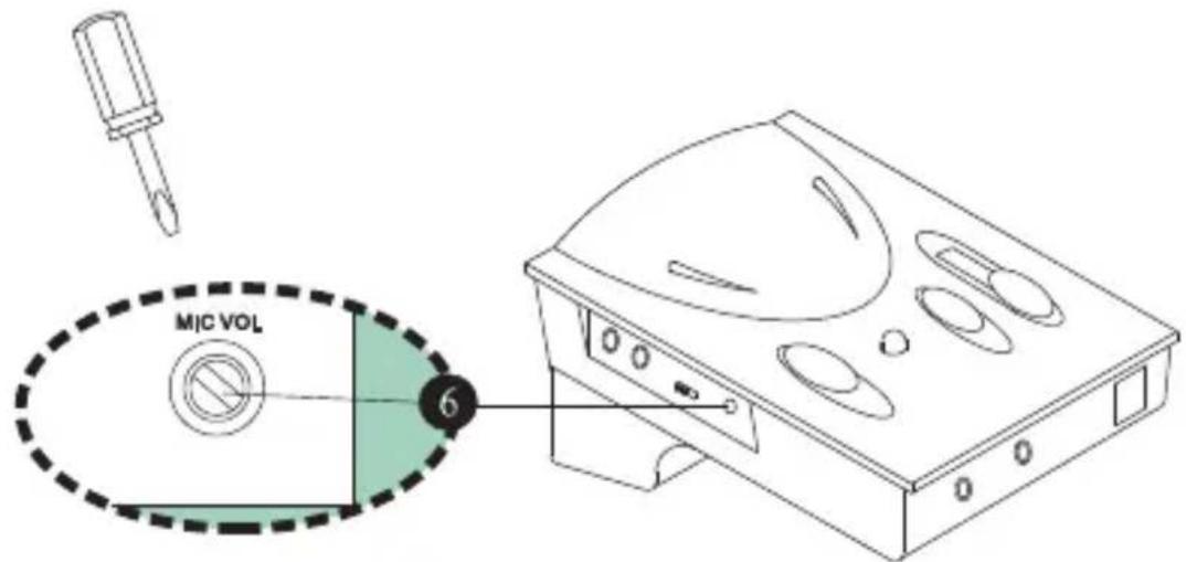
I.3.3 Rotary Transmit Volume Control
The amplifier allows you to adjust the volume of the outgoing sound volume, and the high and low frequencies associated with it. To fine-tune the transmission volume, place a call and talk as usual using the headset. Slowly rotate the Rotary Transmit Volume Control (6) with the small screwdriver pin provided until the desired level is reached. The person talking to you should be able to tell you when the optimum sound and tone level is reached. Once this is set, there should be no need to make further adjustments in the future. (See illustration next page)
CAUTION: Be careful when you adjust the volume control, as rotating the volume to the maximum setting may cause headset to "squeal". Reduce the volume and the "squealing" will disappear, but continuous over-turning of the control may cause damage to the unit.
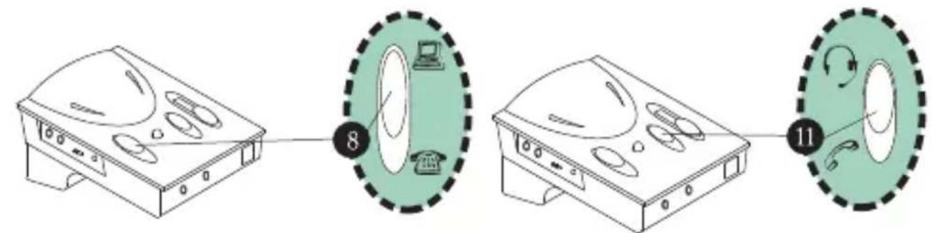
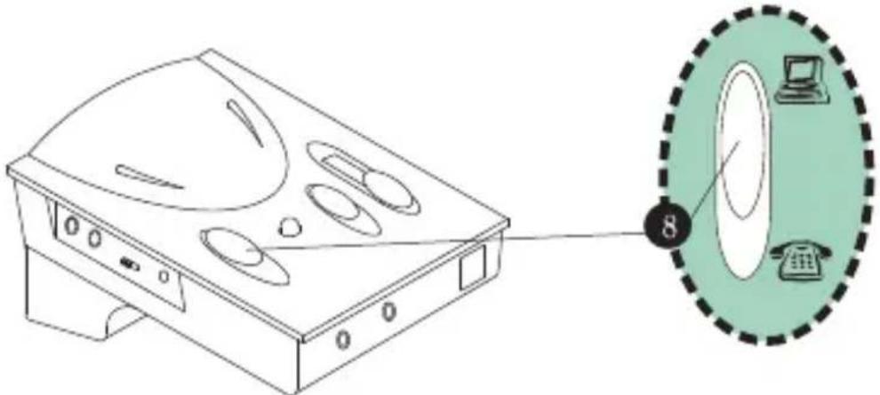
1.3.4 Telephone/Computer Application Switch
The Telephone/Computer Application Switch (8) is for you to select either computer operation or telephone communication. Should this switching result with no sound, be sure to first check the Headset/Handset Application Switch to see if it's set properly.
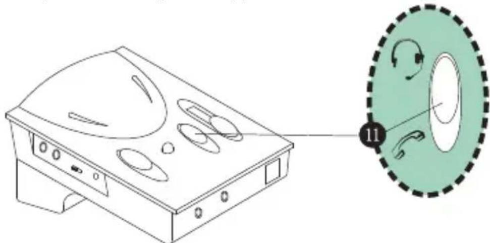
1.3.5 Headset/Handset Application Switch
The Headset/Handset Application Switch (11) is for you to choose between using the handset of your telephone base unit or the telephone headset provided. Again, do not forget to switch the proper setting of Telephone/Computer Application Switch, before use.
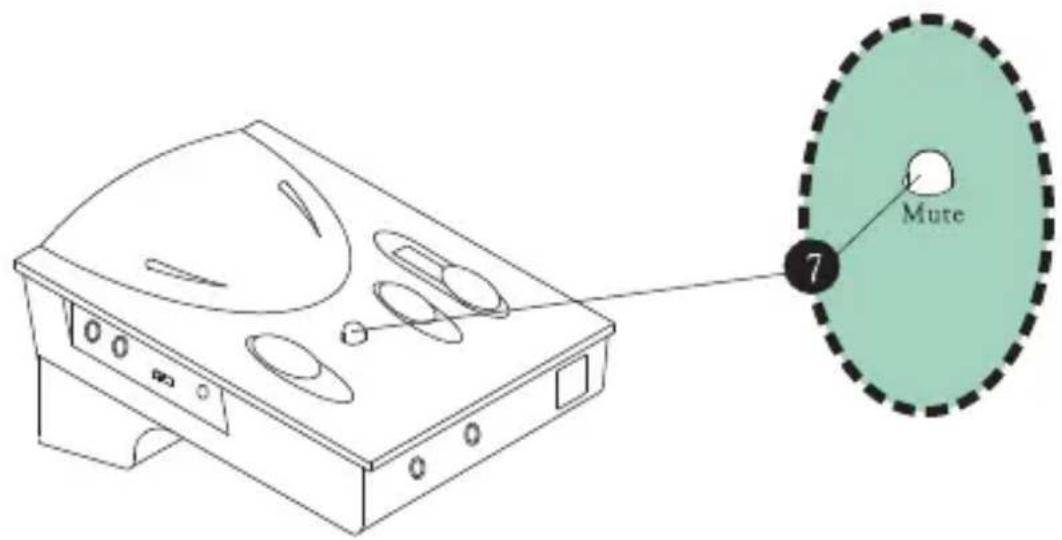
1.3.6 Mute Switch
The Mute Switch (7) enables you to place a caller on hold by pressing it down. When the button is pressed down, the caller cannot hear you, but you can still hear them. To resume communication, press it again to release the button. You can see a color bar surrounding the button, when the color bar is visible, there is no mute, and when the color bar is not visible, then the call is muted.
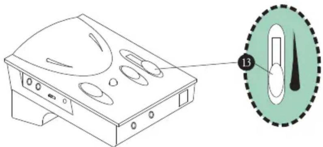
1.3.7 Slide Reception Volume Control
The Slide Reception Volume Control (13) is for adjusting the volume of the sound to the headset speaker or speaker box. By sliding the button up and down, you can obtain the desired volume.
PART II BEGIN TO OPERATE
II.1.1 Receiving Calls/Making Calls Using Headset
Switch the Telephone/Computer Application Switch to Telephone position. Lift up the handset from its cradle and place it off-hook, or with telephones that have a handsfree speakerphone function, choose the Headset switch and press the Speakerphone button. Make sure the Headset position is selected on the Headset/Handset Application Switch. After finishing a call, return the handset to its cradle as usual, or turn off the Speakerphone button. Remember to press the Mute button to put a caller on hold, and simply press it again to release the mute function.
flowchart
graph TD
    A["Headphones"] --> B["Telephone"]
    B --> C["Phone"]
    C --> D["Radio"]
    D --> E["Phone"]
    style A fill:#f9f,stroke:#333
    style B fill:#ccf,stroke:#333
    style C fill:#cfc,stroke:#333
    style D fill:#fcc,stroke:#333
    style E fill:#cff,stroke:#333
II.1.2 Using Headset with Computer
Switch the Telephone/Computer Application Switch to the Computer position. Select Headset position from the Headset/Handset Application Switch for using headset. When a phone call comes in or you want to make a call while doing computer work, simply switch to Telephone position and lift the handset from the cradle or press the Speakerphone button. After the call is completed and you wish to return to your computer work, select the Computer position and place the handset back into its cradle or turn off the Speakerphone button.
II.2 TROUBLESHOOTING
| There is no response from the unit. | Check if the batteries are too low, replace if required.Check if the Polarities of batteries are placed correctly.Make sure the On/Off switched to ON.Check if the Configuration Switch is properly selected.Volume Control and Mute button are adjusted properly.Headset/Handset and Telephone/Computer switches are properly selected.Check if the telephone patch cable is properly connected. |
| I cannot hear any dial tone or caller. | Check if the Telephone/Computer switch is selected at telephone.Make sure the Configuration Switch is properly selected. Try other positions until your hear okay. |
| My Caller cannot hear me at all or cannot hear me very well. | Make sure the Mute button is not pressed down.Use the screwdriver to check if Mic volume is set too low.Try to select the proper settings with the configuration switch. |
| I hear my voice too loud and there is a squealing sound. | The rotary transmit Mic volume control is set too high. Reduce this volume or refer to section 1.3.3. |
| When using with my computer, the sound is too loud even though the volume is set at minimum. | Take a look at the connection on your computer where the cables connect with the amplifier. There should be 3 jacks (line-in, line-out and speaker).Make sure the line-out cable from the amplifier is connected to the line-in jack of the computer.Make sure that the line-in cable from the amplifier is connected to the line-out jack of the computer and NOT the speaker jack. |
PART III ACCESSORIES & SPECIFICATIONS
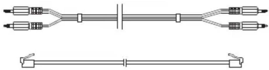
III.1 ACCESSORIES
Compcessory 55251, 55252, 55253, and 55254 Telephone & Multimedia Amplifier Kits come with the following accessories to help you connect to your telephone set or computer.
- One Headset.
- One pair of Computer Patch Cable (See below).
- Telephone Patch Cable with RJ-11 Modular Plugs (See below).
- Screwdriver Pin.
natural_image
Pure electrical circuit lines without any symbolsIII.2 SPECIFICATIONS
Standard Operating Voltage 3V DC
Operating Current (Max) 9 mA
Standby Current 200 mA
Standby Mode Activation 2\~3 min. without signal
Amplifier Gain - Speaker 13 dB (Max)
- Microphone 30 dB (Max)
Battery UM-3 x 2 (size "AA")
Adapter DC Input 6V\~9V DC
(Adapter not included)

Standards Approval

flowchart
graph TD
    A["Ordinateur"] --> B["Laptop"]
    B --> C["Téléphone"]
    C --> D["Handheld telephone with keypad"]
natural_image
Line drawing of a medical device with attached tubing and connector (no text or symbols)BRANCHEMENT SUR LE CASQUE D'ÉCOUTE D'ORDINATEUR :
flowchart
graph LR
    A["Step 8: Display panel"] --> B["Step 11: Control panel with icons"]
    style A fill:#f9f,stroke:#333
    style B fill:#bbf,stroke:#333
1.3.2 Interrupteur ON/OFF (MARCHE/ARRET) (5)
PARTIE II FONCTIONNEMENT INITIAL
natural_image
Pure electrical circuit lines without any symbolsIII.2 SPECIFICATIONS
- Microphone 30 dB (Max)
Batterie UM-3 x 2 (taille "AA")
natural_image
Line drawing of a medical device with attached tubing and connector (no text or symbols)PARTE II COMENZAR A UTILIZAR LA UNIDAD
natural_image
Pure electrical circuit lines without any symbolsnatural_image
Line drawing of a medical device with attached tubing and connector (no text or symbols)natural_image
Line drawing of a device casing with multiple circular cutouts and a dashed circular inset showing a hand gesture (no text or symbols)1.3.6 Interruptor de silenciamento
natural_image
Pure electrical circuit lines without any symbolsIII.2 ESPECIFICAÇÕES
natural_image
Line drawing of a cordless cable with connector and device, no text or symbols presentCONNESSIONE ALLA CUFFIA DEL COMPUTER:
flowchart
graph LR
    A["Device 8"] --> B["Screen with monitor icon"]
    B --> C["Device 11"]
    C --> D["Device 11 with scroll arrow and hand icons"]
flowchart
graph TD
    A["Headphones"] --> B["Wireless Device"]
    B --> C["Telephone"]
    C --> D["Phone with Bell"]
    D --> E["Wireless Headphones"]
    E --> F["Telephone"]
    F --> G["Phone with Phone"]
    G --> H["Wireless Phone"]
    H --> I["Phone with Phone"]
    I --> J["Wireless Phone"]
    J --> K["Phone with Phone"]
    K --> L["Wireless Phone"]
    L --> M["Phone with Phone"]
    M --> N["Wireless Phone"]
    N --> O["Phone with Phone"]
    O --> P["Wireless Phone"]
    P --> Q["Phone with Phone"]
    Q --> R["Wireless Phone"]
    R --> S["Phone with Phone"]
    S --> T["Wireless Phone"]
    T --> U["Phone with Phone"]
    U --> V["Wireless Phone"]
    V --> W["Phone with Phone"]
    W --> X["Wireless Phone"]
    X --> Y["Phone with Phone"]
    Y --> Z["Wireless Phone"]
natural_image
Pure electrical circuit lines without any symbolsIII.2 SPECIFICHE
Tensione operativa standard 3 V CC
Corrente operativa (massima) 9 mA
Corrente in standby 200 mA
ANSCHLIEßen AN DAS COMPUTER-HEADSET:
natural_image
Line drawing of a device casing with multiple circular compartments and a highlighted circular component (no text or symbols)natural_image
Pure electrical circuit lines without any symbolsnatural_image
White silhouette of a classic rotary dial telephone on a green background (no text or symbols)
natural_image
Simple line drawing of a laptop computer with no text or symbols