665201 - Turntable Roco - Free user manual and instructions
Find the device manual for free 665201 Roco in PDF.

| Product type | Turntable for model railways |
| Brand | Roco |
| Model | 665201 |
| Scale | 1/87 (H0) |
| Diameter | 307 mm (including concrete segments) |
| Usable track length | 253 mm |
| Maximum wheelbase | 250 mm |
| Diameter with access tracks | 393 mm |
| Required opening | 280 mm diameter, 50 mm minimum depth |
| Minimum angle between tracks | 9° (progression by 1°) |
| Minimum angle for distinction | 3° |
| Intermediate segments supplied | 1°, 3°, 6°, 9° |
| Maximum number of access tracks | 40 |
| Control mode | Step-by-step (supplied control unit), direct access (ref. 42618), PC |
| Transmission | Two-level worm gear with friction coupling |
| Control power supply | 14-16 V AC |
| Traction power supply | 0-12/14 V DC (2 rails) or 0-16 V AC (3 rails) |
| Replacement motor | Ref. 105284 |
| Replacement brushes | Ref. 89743 |
| Recommended lubrication | ROCO special grease 10905, sewing machine oil |
| Main functions | Motorized rotation, electromagnetic locking, distribution of traction current to access tracks |
| Maintenance and cleaning | Annual lubrication of worm gear and bearings; replace brushes if necessary |
| Safety | Isolated stop zones to prevent falls into the pit; current cut-off switch |
Frequently Asked Questions - 665201 Roco
User questions about 665201 Roco
0 question about this device. Answer the ones you know or ask your own.
Ask a new question about this device
Download the instructions for your Turntable in PDF format for free! Find your manual 665201 - Roco and take your electronic device back in hand. On this page are published all the documents necessary for the use of your device. 665201 by Roco.
USER MANUAL 665201 Roco
The ROCO LINE Turntable
natural_image
3D model of a circular railway track with multiple tracks and a train, set against a blue sky (no text or symbols visible)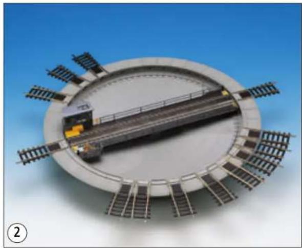
natural_image
3D rendering of a train track inside a circular platform with rail tracks extending outward (no text or symbols visible)Zum Vorbild
natural_image
Diagram of a mechanical or electrical component with multiple wires and a central connector, set against a yellow background (no text or symbols)natural_image
Circular industrial machine with rail tracks and a central platform, no visible text or symbols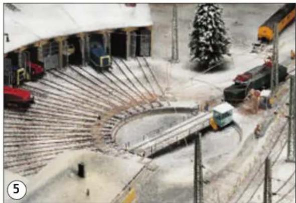
natural_image
Aerial view of a railway construction site with excavators, snow-covered tracks, and a Christmas tree (no visible text or symbols)natural_image
Exterior view of a train station with two green and white trains parked on tracks, surrounded by rail barriers and buildings (no visible text or signage)D Das Modell
Technische Daten
natural_image
Product photo of a train track system with cable, connector, and control panel (no visible text or symbols)natural_image
Two industrial conveyor systems with metal frame and green mesh components, shown against a plain blue background (no text or symbols visible)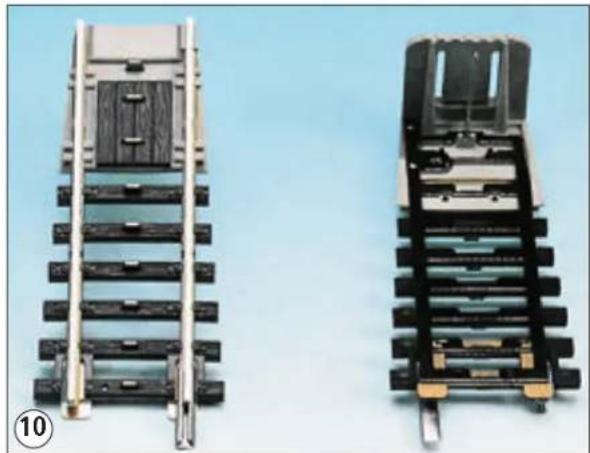
natural_image
Two views of a mechanical device with metal brackets and mounting holes, shown against a plain blue background (no text or symbols visible)natural_image
Pure electrical circuit lines without any symbolsnatural_image
Close-up of a hand adjusting a detailed architectural model of a building structure (no visible text or symbols)D
natural_image
Close-up of a hand interacting with a model of a building structure, showing structural details and red arrows indicating motion (no text or symbols)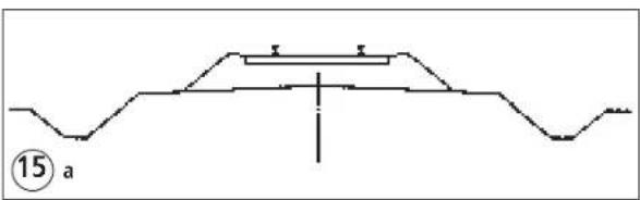
text_image
15 a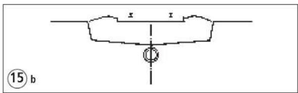
text_image
x x ⑮ b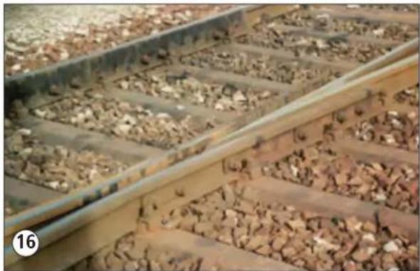
natural_image
Close-up of railway tracks with gravel and dust patches, no visible text or symbolsnatural_image
Four gray plastic chair accessories arranged in a row, each labeled with an angle (1° to 9°) and number (17), shown against a plain white background.Wichtig:
natural_image
Mechanical assembly diagram showing a circular platform with internal components and a magnified inset of a component (no text or symbols visible)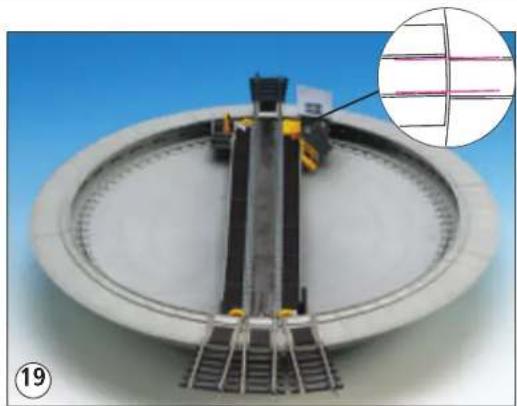
natural_image
Mechanical assembly with a central vertical rail bar and surrounding components, shown with an inset magnified view (no text or symbols)Roco
natural_image
Top-down view of a mechanical assembly with green circuit board and mechanical components, set against a blue background (no text or symbols visible)D
natural_image
Two black electrical connectors with copper wires, one connected to a circular logo (no text or symbols visible)natural_image
Cutaway view of an internal mechanical device with visible components and wiring (no text or symbols)natural_image
Black rectangular electronic device with four pins and a small internal component, shown against a blue gradient background (no text or symbols visible)D
natural_image
Diagram of a fan-shaped structure with internal flow lines and directional arrows, no text or symbols presenttext_image
Racer V1 V2 ① ③ ③ ② ②9natural_image
Close-up of a black electronic device with a rotary dial and indicator lights (no visible text or symbols)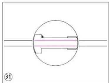
natural_image
Pure mechanical cross-section diagram without any text, numbers, or symbols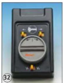
natural_image
Close-up of a black electronic device with a circular dial and control buttons (no readable text or symbols)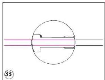
natural_image
Pure mechanical cross-section diagram without any text, numbers, or symbolsRoco
natural_image
Close-up of a black electronic device with a rotary dial and indicator lights (no readable text or symbols)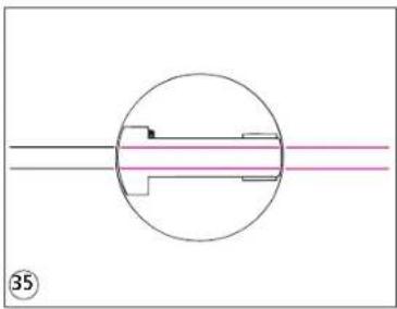
natural_image
Pure mechanical cross-section diagram without any text, numbers, or symbolsD
natural_image
Close-up of a black electronic device with a dial and control buttons (no readable text or symbols)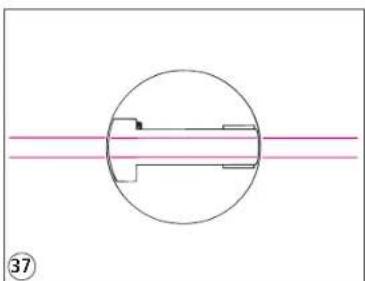
natural_image
Pure mechanical cross-section diagram without any text, numbers, or symbolsnatural_image
Diagram of a mechanical or architectural component with directional arrows and geometric outlines, no readable text or symbols present.Dear Model Railway Hobbyist!
A great wish has been fulfilled with the purchase - or gift received - of this under-table drive as well as simple, understandable electrical components. ROCO LINE turntable. We are aware of your expectations and have given In the following pages we discuss in detail the prototype, technical details, special attention to the design and construction of this operating model. The installation and operation of the ROCO LINE turntable. Please take your time result is a reproduction of a 22 meter (72 ft) standard turntable in exact-scar reading these instructions. Then you will be able to perform the installation le with versatile possibilities (fig. 1: installation with constant separation; successfully and will have many years of pleasure with the reliable operation fig.2: installation with different separations), a durable, quiet and reliable of your new turntable.
About the Prototype
Turntables are almost as old as rails and certainly older than railways; in theods or - today the usual design - made in site concrete (see fig. 4, prototype mines of the early 18th century they were used - in place of turnouts which situation, e.g. in Freilassing, and fig. 5 as model). Until the end of the 80s were invented much later-to interconnect different rail tracks. Along mine- or industrial tracks they are still used today as wagon turntable for this purpose. Compared to the "turntables" used by the "big" railways today, which are actually "turn-bridges" (in some European languages they are actually called by this term), these wagon- and mine turntables are real "tables" with covered pits. With early railways, turntables performed the function of turnouts, especially by the "giants" among the steam locomotives such as class 45, class 05 and in terminal stations. Whether they were built as real turntables or only as table segments they were used not only for turn-around of locomotives but tables were not large enough and finally 27 meter tables were developed for shunting the engines to bypass the trains. Additionally, several station tracks were cross-connected by wagon turntables (see fig. 3) to make it easily few large operations centres where these large engines were stationed or to remove single wagons from the trains and move them, perpendicular to had to turn such engines at the end of their runs. or were supposed to have the station tracks, to other tracks to include them in other trains or for separate shunting. As locomotives and wagons became longer (and heavier), cond World war. With the change in motive power turntables did not become turn tables were no longer used as substitute turnouts; especially the track entirely unnecessary (even though transfer tables took their place at newly cross-connections within stations by means of wagonturntables disappeared. Instead turntables became indispensable components of railway operating centres. Since then, they were designed as true bridges, either with upper chord (relatively rare today) with shallow pit and ballast roadbed or turning even driving trailers with 26.4 meter length as is done routinely in with lower chord (this version is generally used today) and deep pit which the operations centre Freilassing (see fig.6). either secured with masonry and stabilized to the centre pivot with Radial tie
GB The Model
Technical Data
Prototype design 22-meter standard turntable
Model Scale 1:87 (model size HO)
Bridge length of model 253 mm (9.96")
Usable bridge length . . . . . . . . . . . . . . . . . . . . . . . . . . . . . . . . . . . . . . . all rolling stock with total wheelbase not exceeding 250 mm (9.84").
Diameter concrete wall simulation in segments 307 mm (12.1")
Number of possible track connections 40
Diameter overall including all access tracks 393 mm (15.47")
Required diameter of circular cutout in layout table . . . . . . . . . . . 280 mm (11.02")
Required minimum depth of empty space required for installation of turntable beneath the cutout, measured from upper edge of cutout or lower edge of access tracks. . . . . . . . . . . . 50 mm (1.96")
Smallest departure angle between two adjacent tracks . . . . . . . . . 9°
Possible departure angle between adjacent tracks. . . . . . . . . . in steps of 1° starting at 9°
Smallest angle between two track centres for reliable recognition of track connection by the turntable control . . . . . . . . 3° (see fig. 7)
Angle of available concrete segment(filler pieces) 1°, 3°, 6° and 9°
Control modes (track selection) ..... a) single-step progress with manual control (operating switch included with set);
b) direct selection of track wanted through pre-selector control Art. no.42618
c) control via PC (however required interface currently not planned for production!).
Powertransmission....via combined, two-stage worm gear and multi-stage spur gears; the second worm gear is directly attached to the bridge pivot and connected to it by a slip clutch so that the bridge can be turned by hand without damaging either of the two worm gears!
Roco
Contents of Set
GB
The following parts and assemblies are included in the turntable set as delivered:
- 1 turntable pit, equipped with complete bridge (including motor shed, imitation of hand crank with locking lever, etc.), permanently installed under-floor drive, complete 360° attached concrete filler pieces with 24 pieces 9° and 24 pieces 6° segments, without access tracks.
- 1 package art.no. 42616 with four access tracks for 2-rail 2-conductor DC layouts; (*)
• 1 bag with 12 pieces 3° and 12 pieces 1° filler pieces; - 1 bag with 2 simulated bridge signals and two contact coil springs for position indication of the turntable bridge;
• 1 manual control unit;
• 1 Power distributer - 1 8-conductor connecting cable turntable/manual control unit with 8-pole flat connectors attached at each end:
- 1 5-conductor connecting cable manual control unit/control transformer with 5-pole flat connector attached at manual control unit and ends
with insulation removed at the other end for attaching to the control transformer:
• 1 four-colour instruction booklet (German language);
• 1 B&W, text only, manual (English).
(*) = The factory-delivered turntable contains one set of access tracks for 2.1 mm (code 83) 2-rail DC layouts. If the turntable is to be used for a 3-rail AC layout your stockist will, at your request and without charge, exchange the supplied package with 2.1mm 2-rail track against one containing 2.5 mm 3-rail AC access tracks.
Please Note!
Only complete packages will be exchanged, i.e. one package art.no. 42616 against one package art.no. 42617, but not individual access tracks!
Also refer to the explanation of the intentionally different number of tracks in art.no. 42616 (4 access tracks) and art.no.42617 (3 access tracks) in the last paragraph on page 6.
Installation Requirements
1) Power supply
a) Control and drive motor: 14-16 volt AC
b) Running current within the turntable area: same as used on the layout everywhere else:
- either 0 -12/14 volt DC (international standard 2-rail DC system);
- or 0-16 volt AC (3-rail AC system with centre conductor; on access track with centre-stud contacts, on the bridge with simulated ribbed sheet metal cover between rails).
It is recommended to assign a separate control transformer to the turntable and its surrounding operating area in both 2-rail DC and 3-rail AC systems; the illumination/ magnetic ar-ticle output terminatsof this transformer are used for operation of theturntable and possible' illumination of the area, while the running power output terminals are used to supply running power on the turntable and surrounding areas. A control transformer with extended slow-speed range of the running power is particularly well-suited (e.g. ROCO 10704) since it permits very sensitive shunting.
2) Mechanical track standards:
a) Bridge
The rail profiles on the bridge are designed to accept wheel profiles according to NEM (and MNRA) as welt as wheel sets used with 3-rail AC systems which generally use higher wheel rims.
b) Access tracks:
As shown In the list of supplied items (page 5 of these instructions) the turntable is factory delivered with a package art.no. 42626. If the turntable is to be used on a layout built with 3-rail AC track, the access track package 42616 (with four access tracks without centre studs) should be exchanged, at time of purchase, against a access track package 42617 (containing three access tracks with centre stud contact, as previously described in chapter "Contents of Set" on page 5. In case of "K" track of the 3-rail AC system no additional parts are required, for "M" track the system-specific conversion tracks from "M" to "K" track must be provided additionally.
The different number of access tracks in package 42616 (fig. 9, access track for 2-rail DC layouts) and 42617 (fig. 10, access track for 3-rail AC layouts) are not errors in packaging but compensate the difference in manufacturing cost and selling price so that access track packages can be exchanged against each other without price differential).
Notes:
a)
If the turntable is used on 2-rail DC layouts with 2.5 mm (code 100) profile track (e.g. standard ROCO track system) where only rolling stock with wheelsets conforming to NEM or NMRA standards are used, the access tracks from package 42616 can be used. All access tracks which are directly joined to 2.5 mm rails of the layout must be connected with the transfer fishplates (rail joiners) 42612 (see fig. 11).
For simplicity it is recommended to use the ROCO LINE track without road - bed for the connecting shed tracks which have no further connection to the remainder of the layout even though the entire layout is set up with 2.5 mm profile track.
b)
When using the turntable on layouts with hollow profile rails (especially existing PIKO- or HRUSKA track systems) the transfer tracks 42414 must be used instead of transfer fishplates (see flg. 12). The recommendation made in a) above is equally applicable to the shed tracks.
c)
Use of the turntable on layouts with rolling stock having so-called "fine-scale" wheelsets (RP 25 of NMRA) is possible without limitation or change when using access tracks 41616.
3) Installation location:
To assure trouble-free operation of the turntable for many years it is important to make sure that the area of the layout where the turntable will be located is absolutely flat and horizontal. Only then is it possible to avoid hardly visible twisting of the turntable pit during installation which will result in uneven movement of the bridge and unreliable operation!
GB
Installation Procedures: Mechanical
a) Insertion and removal of access tracks and filler pieces:
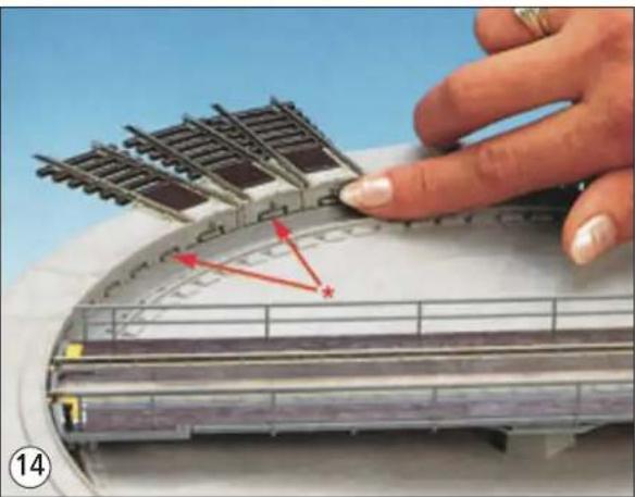
Around the concrete pit of the turntable a segment-receiving groove, open towards the top, is provided (fig. 13, detail*; along its inner (higher) edge runs a locking collar around the entire pit (fig. 13, detail**). The access tracks as well as che filler pieces have a flexible locking projection along their front sides (fig. 14, detail*). If an access track or filler piece is pushed into the groove to the detent, the locking projection will engage audibly into the locking collar of the pit. To remove a filler piece or access track the locking projection must first be pushed in slightly with a finger nail or small screw driver (see fig. 14) and then lift off the part while still pushing in the locking projection.
b) Preparation of the surface:
Regardless whether the layout is built as frame-or panel system it is recommended to construct the locomotive service area consisting of turntable, loco shed and other facilities on a sturdy panel with framing supports, paying attention to install the panel flat and horizontally. A circular hole with 280 mm (11") diameter is cut into the panel. The outside diameter of the turntable pit has only about 270 mm diameter, the remaining 2x5 mm difference are needed for placement of the interrogation contact connections underneath the access tracks for the track pre-selection control (art.no. 42618). These spaces in the vicinity of the access tracks must be available under any circumstances; otherwise damage to these contacts can occur and cause malfunctioning of the track pre-selection control! Since prototype tracks are usually placed in "sunken roadbeds" (see figs.15b and 16) throughout the operating centre, as has been indicated in the access tracks to the turntable, it is recommended to use ROCO LINE track without ballast roadbed for the shed tracks and those of the loco servicing facilities and to switch to ROCO LINE track with roadbed only where the service area tracks join the remainder of the layout. Analogous considerations apply to other track systems (for 3-rail AC system "K" track should be used for the service area and, if wanted, "M" track for the remainder of the layout).
c) Direct siding track of the turntable to ballast roadbed track (ROCO-LINE with ballast roadbed track or ROCO geoLINE):
However, if the loco shed area including the shed tracks is to be equipped with ballast roadbed tracks, the upper edge of the track of the turntable platform and its spur tracks must be elevated to match the level of the ballast roadbed tracks leading to the turntable first. This is done by placing plywood, cardboard, or rigid Styrofoam (thickness of approx. 6 mm) underneath the filler pieces and the spur tracks. Continue building the tracks as follows:
- For ROCO-LINE ballast roadbed tracks: It is now possible to connect these directly to the spur tracks of the turntable since track profile, railroad tie shape, and track rail bond match one another. The spur tracks themselves must be positioned with ballast as needed (suitable track ballast: Item No. 42652); the space between the spur tracks can also be filled with the ballast plate (Item No. 42653) if and as needed.
- For ROCO-geoLINE ballast roadbed tracks: The easiest solution here to create the transition from the geoLINE track to the respective spur track is to use the junction track Item No. 61120. Continue as described for the ROCO-LINE ballast roadbed track.
If this solution is not feasible (for example, due to space restrictions), the geoLINE track can be slightly "modified" to directly connect to the respective spur track by using the ROCO hobby saw Item No. 10900 or a similar tool to saw off the guide tongue located directly underneath the rail bond on the geoLINE track end to be connected to the spur track of the turntable. This is possible because track profiles and rail bond match exactly between the new ROCO-geoLINE track and the ROCO-LINE track without ballast and with that the twin-conductor DC spur tracks of the turntable as well. Continue as described for the ROCO-LINE ballast roadbed track with this solution, too.
d) Fitting the turntable Into the cutout of the layout.
After having cut the required hole into the baseplate of the operations centre area, the turntable is temporarily equipped with 3 access tracks at 120° or 4 access tracks at 90° separation and then placed into the cutout. It is not necessary to have alt possible filter pieces installed! In the cutout the turntable including pit, access tracks and filler pieces is rotated carefully to check if the free space in the cutout is sufficient for the later, permanent installation. If one of the interrogation contacts touches anywhere along the cutout edge, even though the turnout itself is centered in the cutout, the cutout edge must be reworked sufficiently at this point! Otherwise damage to the contacts can take place during final installation of the turntable! If this insertion test is entirely satisfactory, the turntable is removed for final attachment of tracks and filler pieces.
e) Installing turntable access tracks:
As long as the turntable is not equipped with all possible access tracks it is recommended to select the part of the concrete rim which is factory equip - ped with 9° filler pieces for the largest section without access tracks, to remove the adjacent 6° filler pieces as described under a) of this chapter and then attach the first access track directly adjacent to a 9° filler pieces According to the planned loco service and engine shed tracks, all additional access tracks are attached with the desired angles, whereby angles between adjacent tracks do not have to be equal (see page 2, fig. 1, equal angles, and fig. 2, different angles) but can be freely selected (also see the following suggestions especially regarding "opposite access tracks"!). Afterwards the remaining empty spaces between tracks are covered with matching filler pieces. Depending on the extent of the open space one or more filler pieces with 1°-, 3°-, 6°- or 9° segmentation will be required - see fig. 17. If the connecting tracks sections are already within the engine shed, the service- or entrance/departure area, the exact position of the access tracks should be checked by temporary insertion of the turntable into the cutout hole before the filler pieces are attached. A necessary correction of location or angle of an access track which does not exactly match its connections to another track can be done much easier before the filler pieces are attached then afterwards'
Important:
If, at a certain position of the bridge, access tracks should connect at both ends it is important to make sure that the rail profiles of both access tracks are exactly in line with those of the bridge raits! This is done easiest as follows:
- First insert only one of the access tracks at the location wanted into the receiving groove until it engages audibly.
- Turn the turntable manually to this access track and align it so that the inner edges of the bridge rail profiles are exactly in line with the profiles of the access track! As soon as this done the bridge must not be moved again.
- Attach the second access track at the opposite, still open end of the bridge by inserting it until fully engaged.
- Align the second access track by slight movement to the right or left until the inner rail edges of this access track match exactly with the inner edges of the bridge rail profiles (see fig.18).
- Finally perform a visual check by sighting along one inner rail edge from the front access to the rear access track across the bridge rails. No offset must exist between the inner edges of all three rail sections (not like fig.19). Otherwise the alignment procedure as described must be repeated to assure trouble-free passage across the bridge.
If however at two opposite access tracks an (angular) offset should be in - stalled deliberately (e.g. to avoic tight radius curves or unsightly kinks) care must be taken that the offset to the exact alignment is at least 3° (see fig. 7, page 4) so that the turntable control can reliably recognize the diffe
Roco
operations centre and the location of the turntable in it care must be taken that the turntable. after permanent attachment, remains easily accessible from the underside as well after the scenery has been completed. This makes the placement of electrical cables and possibly the retrofit installation of the return indication unit of the pre-selection control art.no. 42618 easier
and also facilitates the occasionally necessary maintenance- and lubrication work (see fig. 21). It should be avoided to place tunnel tracks or hidden storage sidingsdirectly below the turntable which will prevent or reduce access to the underside.
GB
Installation Procedures: Mechanical
a) Wiring:
As a result of cleverly designed controls and utilization of the ROCO flat cable- and connector system the wiring of the turntable has been reduced to an essential minimum; the required cables are furnished with the turntable set, complete with flat connectors attached. The 8-conductor flat cable, factory-equipped with connectors at each end, is used to connect the protected but easily accessible 8-pole contact terminal of the under-floor turntable drive with the 8-pole (i.e. broader) contact terminal of the hand control unit (see fig. 22, detail *).
Additional connections between turntable and control unit or turntable and remainder of layout are not necessary!
The 5-conductor flat cable connects the manual control unit with the control transformer assigned to the operating centre area (see fig. 22, detail **). The brown and green wires supply running power to the turntable bridge track and access tracks and are connected to the running power output terminals of the control transformer (0 to 12/14 volt DC if the turntable is used on a layout operated with the 2-rail DC system; 0 to 16 volt AC on layouts with 3-rail AC system). The yellow (slightly shorter) wire in the centre of the flat cable has no function and is not connected. The grey and pink wires supply power for control, turntable drive motor and locking magnets. The entire control, etc. operate with alternating current (AC), therefore these two wires are connected to the illumination/magnetic accessories output terminal of the control transformer (see fig. 22, detail **). The DC required for the bridge motor is produced within the manual control unit by a built-in rectifier.
The turntable control must never be operated with direct current (DC); even though this would not destroy the control circuits and manual unit it would lead to malfunctions of important turntable functions. Both the 8- and 5-conductor cables can be extended to practically any length with the 8-conductor (art.no. 10628) or 5-conductor (art.no. 10625) flat cables, the matching flat connectors (8-pole = art.no. 10608, 5-pole = art.no. 10605) and the matching connector platelets from set art.no. 10598.
Note:
When attaching the flat connectors to the contact terminals of the turntable and manual control unit it is most important to assure that the one-sided contact surfaces of the connectors face the contact surfaces of the turntable and manual control unit terminals, otherwise neither running power nor control commands can be transmitted!
b) Preparation of the turntable control:
The turntable can be operated with the manual control unit supplied or the pre-setector control which is not yet available. To correctly process the control commands received the turntable must know whether the commands come from the manual or preselector control. At the underside of the turntable, on the cover of the underfloor turntable drive, are two slide switches, the upper has the symbol = and \~, the lower the numbers 0 and 1 (see fig. 22, detail ° for the turntable and fig. 25, detail * for the manual control unit):
- If the lower switch is at position "1", the turntable will interpret all commands all commands as coming from the manual control unit.
- If the switch is moved to position "0", the turntable will interpret all incoming commands as coming from the pre-selector control, but it can process the commands only if additionally all interrogation switches below the access tracks have been connected to the pre-selector control.
How this is done will be described in the installation- and operating instructions of the preselector control when it becomes available.
Attention:
For operation of the turntable with the manual control unit this switch must be in position "1"!
c) Selection of the running power system:
Since the turntable has been designed for operation with both the 2-rail DC and 3-rail AC system, the model railway hobbyist makes the final decision regarding the running power system by his choice of access track type (art. no. 42616 for DC, art.no. 42617 for AC system), additionally it is necessary to switch the electrical power path within the turntable area. This is done by the sliding switch with the symbols = and \~ at the underfloor drive of the turntable (see fig. 22, detail °) and an equally designated slide switch on the underside of the manual control unit (see fig. 25, detail *).
Please note:
Reliable operation with the system selected is only assured when both running power switches are placed to the same system symbol: either both on = or \~! Different switch positions will inevitably cause trouble during operations.
Note:
As delivered from the factory, the turntable and manual control unit are set for 2-rail DC operation (both switches are set to position "=").
d) Separation of running power supply between turntable/engine shed area and remainder of layout:
At prototype facilities, the operation centre is a separate area as far as operations and safety are concerned: in small to medium-sized centres the relevant turnouts are manually operated and engines proceed pedestrian speed with "on sight" control. Only large operations centres have their own signal box and possibly internal signal controls. All entry- and exit tracks between the centre and other railway facilities are protected by waiting- and/or track locking signals, in case of greater distances between the centre and other facilities, block signals may be added.
The correct and trouble-free operation of the turntable requires similar considerations before placing it in a layout. This means: all tracks leading from the turntable to the other parts of the layout must be electrically isolated; isolating fishplates (rail joiners) for 2-rail DC systems and centre rail insulators for 3-rail AC systems must be inserted at least the length of a large locomotive (approx. 30 to 35 cm/12 to 14") distant from a turntable access track which connects to remainder of the layout (not necessary for dead-end sidings or engine shed tracks). For DC operation it must be differentiated if the power to the turntable area is supplied from the same control transformer as the rest of the layout (for operating and electrical reasons, the more unsatisfactory situation since an additional polarity-reversing switch must be provided in the running power supply cable (see fig. 26, arrow) or if two, electrically independent control transformers are to be used (the preferable situation). If only one control transformer is used, two isolating fishplates must be used at each circuit separation location in the track(s) leading to the turntable (one isolating fishplate in each rail (see fig. 27). When two electrically independent control transformers are used, one isolating fishplate per separation point is sufficient (see fig. 27, detail*). More reliable, versatile and in view of future changes (possible change-over to digital operation) it is generally
GB
advisable to equip all circuit separation points in 2-rail DC system with two isolating fishplates (see fig. 27 details * and**, also fig. 28).
Note:
On layouts with digital control these separations must, in all locations, be done in two polarities i.e. with one isolation fish plate on each rail profile!
The separation of the access tracks is principally necessary for two reasons:
• Operational reason:
Without this stopping section ahead of the turntable pit it would be possible that a locomotive does not stop in time ahead of the pit and runs into the pit if the bridge has not (yet) lined up with the access track. This "event" is sometimes quite "prototypical" but neither in reality nor on the model railway desirable...
• Electrical reason (as protection primarily during DC operation):
First, the running power of all access tracks leading to the bridge should always be controlled from the bridge i.e. the manual control unit or the pre-selector control because only in this situation the model railway operator has effective control overturntable operations.
Secondly it is also an electric protection because, without this electrical separation, the danger of short-circuits in the running power circuit exists at certain positions of the bridge. Synchronization of the running current polarity is, without greater complexity, only possible with two separate control transformers (one for the turntable area, another for the adjacent layout area). It is recommended to install polarity indicator with LEDs which is easily built by the modeler (described in ROCO Report
no. 20, page 11, German text). It will greatly simplify the operations within the operations centre and turntable area.
Notes:
1) As long as engine shed, storage sidings and maintenance facility tracks do not have any connections to the other tracks on the layout and are only connected to the turntable, no electrical separations are required in such tracks.
2) Normally, only two or three track connections will exist between the turntable and the other tracks, namely one track connecting the turntable with locomotive servicing facilities (slag removal-/coaling- and run-around track and leading to the major entry-/exit of the operating centre, another, the so-called auxiliary exit track which is often placed to bypass the service tracks and leads in the direction opposite to the major exit track. If the bypass track is not connected at both ends to service track by turnouts but if one end leads directly to the turntable, the third direct connection exists (see fig. 28: black shows the shortened operation centre track plan, green the normal connection of the bypass track via turnout, blue the alternative connection via turntable). Consequently in the usual situation, only two tracks have to be equipped with stopping sections and require installation of isolating fishplates.
3) Engine shed tracks which are only connected to the turntable and not with any other layout tracks do not require isolating fishplates in one or both rails since the power-on and off change is performed by the turn - table control.
Operating with the manual control unit
Functions of the manual control unit:
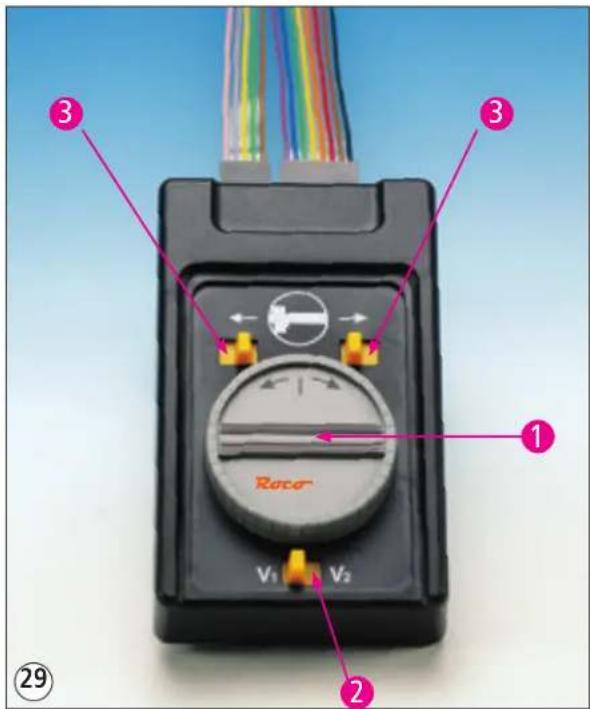
The manual control unit, together with the speed control knob of the control transformer assigned to the turntable area, represents the command post of the turntable operator and therefore all operations in the vicinity of turntable and engine shed. Fig. 29 shows the operating elements of the manual control unit. They perform the following functions:

station selector knob: As long as it is at rest the bridge remains fixed in its last position. If the knob is turned shortly to the right and released again so that it returns to its rest position, the turntable will move towards the left until it reaches the next track connection. In this case both bridge ends have "equal weight".
The same applies to a short turn of the knob to the right when the bridge will turn towards the right until it reaches the next track connection. Direct approach to a specific track, if other tracks are interspersed, i.e. without stopping at the intervening tracks is only possible by holding the knob in the direction wanted until no more tracks are between current bridge position and the wanted track.

speed selector switch for rotation speed of the bridge. The ROCO LINE turntable has, the same as its prototype, a slow and a moderately fast rotation speed. If the switch is in position V1 the bridge rotates slowly and in position V2 it rotates faster. A (prototypical) change of speeds during the rotation is possible. In accordance with the prototype regulations it is recommended to use the slow speed for short turns, the faster for longer rotations especially when a locomotive is being turned by 180°.

elector switch for running power switch-on/off in the tracks connected to the bridge. The following applies:
a) If the switch is adjacent to the turntable symbol, the running power in the adjacent track is turned off. If the switch is moved in direction of the arrow away from the symbol the running power in the track adjacent to the bridge is connected to the bridge power and will always have the same polarity as the bridge!
b) Please note that the left side switch always controls the running power of the turntable (access) track adjacent to the bridge end carrying the engine shed, white the right side switch controls the running power of the (access) track adjacent to the bridge end which is at the side opposite from the engine shed.
text_image
① Rocor V1 V2 ② ③ ③ ③ ②9Roco
This results in four possible combinations of switch positions:
- Both switches are next to the turntable symbol: running power is applied only to the turntable bridge track itself (see figs. 30 and 31, page 15).
- The left switch is set away from the turntable symbol in the direction of the arrow, the right switch is next to the turntable symbol: the track adjacent to the engine-shed end of the bridge is powered, the other track is turned off (if in the current bridge position tracks connect to each bridge end)(see figs. 32 and 33).
-
The right switch is set away from the turntable symbol in the direction of the arrow, the left switch is next to the turntable symbol: the track adjacent to the engine-shed end of the bridge is turned off, the other track is powered (if in the current bridge position tracks connect to each bridge end) (see figs. 34 and 35).
-
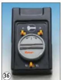
Both switches are set away from the turntable symbol in direction of the arrows: if in this situation access tracks are in line at both ends of the bridge, they are now continuously powered as through-track. This makes sense when a locomotive, coming from the service facilities, should proceed directly across the bridge into an engine shed track at the opposite side, or proceed from the engine shed directly to an exit- or bypass track without having to be turned in between (see figs. 36 and 37).
GB
Generally, the following applies:
Case 2 or 3 are applicable when a locomotive should proceed on to the bridge or leave it. Not absolutely necessary, but as safety measure for normal layout operation it is recommended to set case I while the bridge is turning and to set the speed control at the control transformer to "0". This will definitely prevent unpleasant "surprises"!
Maintenance of the drive unit:
a) Lubrication of the drive unit:
As is the case with all motorized ROCO models, great care was taken to make the mechanical parts of the drive unit as rugged, wear-resistant and maintenance-free as possible; this includes an effective protective cover for the entire under-floor drive mechanism. Nevertheless, from time to time the turntable "underground" should be inspected. To this end, initially remove the protective lid from the circuit board of the underfloor drive. As is shown in Figure 38 the small crosshead screw in the depression of the protective lid must be loosened and completely removed as a first step. Then introduce a flat medium-size screwdriver in the demoulding openings of the mounting claws on the switch side of the protective lid – as also shown in Figure 38 – and slightly force the claws to the outside to separate them from the circuit board. Then tilt the protective lid downwards. Once this has been done the protective lid will automatically release the circuit board on the other side and the protective lid can be completely removed. Now the entire drive mechanism is open and the large drive worm gear can be lubricated (e.g. with the special ROCO gear grease 10905, see fig. 21, page 10, orange arrows. Occasionally, but not too often, the bearings of the worm gear shaft (see fig. 21, page 10, green arrows) should receive a small drop of thin, resin-free sewing machine oil.
The zinc-alloy motor chamber contains all other gears. It is supported by vibration-damping soft-plastic plugs, one each is located between screw-head and motor chamber and between motor chamber and gear frame (pit of the turntable) for each screw to reduce noise. These three screws should be removed to be able to service the second worm gear stage at the motor side. Care must be taken not to lose the soft-plastic plugs and to avoid breaking off the motor wires while carefully removing the motor chamber from the circuit board!
To be able to lubricate the second worm gear, directly next to the motor and the adjacent multi-stage spur gear, both screws of the gear cover near the motor must be unscrewed and the cover removed (see page 12, fig. 24, black arrows). The worm gear located above the slip-clutch on the motor shaft should also receive a little ROCO special grease (see page 12, fig. 24, blue arrows). Finally, the worm gear wheel bearings (red arrows) should also be lubricated with and occasional drop of resin-free, thin sewing machine oil. Please do not lubricate too much! Only one "lube-service" per year is necessary even for frequent operation of the turntable.
After completion of the lubrication the motor chamber must be screwed back in its correct position (do not forget the vibration-damping soft-plastic plugs and the correct insertion of the drive shaft to the large worm gear!). Then the protective cover is clipped back in the correct position. Please pay attention to the two operating mode switches to so that they are placed into the openings of the cover rather than being pushed down. If everything has been properly assembled check the position of both operating mode switches and id necessary, correct to conform to the turntable operating mode applicable to your layout.
b) Replacement of the motor brushes or of the drive motor:
To have access to the drive unit, consisting of motor, slip clutch and motor worm gear, proceed in the same manner as described above for lubrication.
- Replacement of the drive unit: Remove the slip clutch and motor worm gear located on the drive shaft together with the motor itself, after taking off the motor protective cover (unscrew two screws for this), carefully from the gear box, then lift the motor out of the contact springs at the commutator side of the motor.
Install new drive unit (replacement part no. 105284) in reverse order of disassembly, make sure that the contact surfaces of the brush-bearing screws come to rest correctly between the contact springs of the circuit board and are not bent. See fig. 21, black arrows. - Replacement of the drive motor commutator brushes: Proceed exactly as described above for "Replacement of the drive unit" until has been removed from the housing. Then unscrew the brush bearing screws from the motor frame (Careful! the springs located inside the brush bearing screws tend to jump away while doing this work and are then hard to find especially on carpeted floors...), remove brush springs and worn brushes, and if necessary clean brush channels and commutator with a lintfree cloth patch (possibly soaked in lighter fluid). Insert the new brushes (replacement part no. 89743) and brush springs into the brush bearing screws and screw these into the bearing. Assure that the screws are inserted straight and not at an angle, otherwise the threads could be damaged.
The remaining assembly proceeds as already described above under "Replacement of the drive unit".
"Manual operation" of the turntable with control power switched on
Due to the presence of the slip clutch it is always possible, if necessary, to turn the bridge by hand. Corresponding to the last direction of rotation set by the manual control unit, it will continue to turn automatically until it rea
ches the next following access track in the direction of rotation. Here it will stop. This operating possibility can be useful if the manual control unit has been placed at an appreciable distance away from the turntable.
Scenic completion of the operations centre
The turntable is certainly the central object in every operations centre or train dispatch facility, as it is called in Austria. Therefore a great number of buildings and facilities which are essential for supply and maintenance of locomotives are located in its vicinity. Many suitable building and structure kits a
re available, among others those of the firm Faller. As a suggestion, several pictures of an operations centre layout, excellently built with Faller material by Bruno Kaiser, Cologne, are shown.
GB
To this end, initially remove the protective lid from the circuit board of the underfloor drive. As is shown in Figure 38 the small crosshead screw in the depression of the protective lid must be loosened and completely removed as a first step. Then introduce a flat medium-size screwdriver in the demoul ding openings of the mounting claws on the switch side of the protective lid – as also shown in Figure 38 – and slightly force the claws to the outside to separate them from the circuit board. Then tilt the protective lid down - wards. Once this has been done the protective lid will automatically release the circuit board on the other side and the protective lid can be completely removed.
After this, clip on the protective lid in the correct position. When doing so please pay attention also to the two operating mode selector switches so that these engage correctly in the appropriate recesses of the protective lid and are not forced down! Once the protective lid has been clipped on correctly and the two switches are neatly seated in their respective protective lid recesses, re-insert the small crosshead screw in its depression and finally tighten it. Please do not overtighten the screw to avoid damaging the thread. Once everything has been down correctly please check the position of the two operating mode selector switches and readjust in accordance with the operating conditions for your turntable applicable to your system if required.
Drive current polarity display
a) Basics:
Since it is necessary for the control of the radiating tracks (shed tracks, maintenance tracks, other siding tracks and access tracks to the turntable) that the radiating tracks are supplied with drive current from the turntable platform, all tracks leading to the remaining system must be insulated on both poles as shown in drawing 26. Only then is it possible for the control of the radiating tracks from the turntable to operate correctly. Based on this type of drive current feed however there is a risk that "hostile" polarities will meet at the transition point formed by the insulating rail connectors of the access track fed from the platform to the remaining system so that a complete short circuit is created at the moment this point is passed.
Since with digital operation the actual respective polarities in the tracks left and right of the insulating rail connectors play no role with regard to the direction of travel of the locomotive passing that point and it merely needs to be ensured that the polarities on both sides of the insulating rail connectors are identical, this problem can be resolved in digital mode by using the return loop module as already described at another point in these instructions.
In classic DC mode for which the turntable is also designed the situation is slightly different. Here the respective polarities left and right of the insulating rail connectors need not only be identical – as in digital mode – but they also decide in which direction the locomotive will continue to operate. We therefore have to ensure that the polarities do not only correspond to each other but that they are also applied correctly – coming from the turntable platform – so that our locomotive is able to continue moving in the desired direction.
b) Practical application:
With the two-pole changeover switch depicted in drawing 26 (see arrow) this polarity adaptation can be accomplished easily. However this does not provide any information as to whether the polarities are really matched. With a total of four light emitting diodes (practically two green and two yellow) and two resistors for current limitation in the light emitting diodes per connecting track and the remaining system it is possible to very economically establish the monitoring circuit shown in the detail magnifier (drawing 26a).
If the light emitting diodes are correctly installed the lighting up of both green light emitting diodes will not only indicate that the polarities match on both sides of the insulating rail connectors, but also that the direction of travel so set leads from the turntable away to the rest of the system. However if both yellow light emitting diodes light up this means that the polarities on both sides of the insulating rail connectors match again, but that the direction of travel now set leads away form the remaining system to the turntable platform.
However, should a green and a yellow light emitting diode light light up this means "imminent danger" that a locomotive will cause a complete short circuit when passing the insulating rail connectors since the polarities are not matched. In this case it does not matter on which side of the insulating rail connectors the yellow and on which the green light emitting diode should light up. To purely avoid the short circuit it is immaterial which of the two light emitting diode colours happens to be "active". However the decisive point is that the light emitting diodes with the same colour light up on both sides of the insulating rail connectors.
For practical purposes it is advisable to install the two-pole changeover switch and the total of four light emitting diodes (one green and one yellow on the left, the other green and yellow on the right) in a common box accommodated in the vicinity of the manual control unit for the turntable.
c) Note:
The two-pole changeover switch, the light emitting diodes and the resistors are not part of the scope of supply of the turntable.
This circuit cannot be used for digital operation or in a 3-conductor alternating current system!
Roco
F