
SpectraView 1990p - Monitor NEC - Free user manual and instructions
Find the device manual for free SpectraView 1990p NEC in PDF.
| Brand | NEC |
| Model | SpectraView 1990p |
| Product Type | Color LCD Monitor |
| Screen Size | 19 inches (diagonal) |
| Optimal Resolution | 1280 x 1024 pixels |
| Video Inputs | DVI-I (digital/analog), Mini D-Sub 15-pin |
| Power Consumption | Reduction up to 50% in Eco Mode |
| Power Supply | 220-240 V AC, 50/60 Hz (power cord supplied according to country) |
| Ergonomics Adjustments | Tilt 30°, swivel, rotation (landscape/portrait), height adjustable |
| Main Functions | OSM (on-screen manager), auto brightness, color control (7 presets), sharpness, auto adjustment, video detection, programmable shutdown, IPM (power saving) |
| Ambibright Sensor | Ambient light detection for automatic brightness adjustment |
| Built-in Speakers | Optional (MultiSync Soundbar) |
| VESA Mount Compatibility | Yes, 100 mm pitch (4 screws provided) |
| Maintenance and Cleaning | Soft non-abrasive cloth, no solvent or glass cleaner for the screen; housing with diluted neutral detergent |
| Safety | Do not open the housing, disconnect if damaged, avoid liquids and objects, use only suitable cord |
| Spare Parts and Serviceability | No user-serviceable parts; refer service to qualified technician |
| Certifications | ENERGY STAR, CE compliance (EN 60950-1, EN 55022, etc.) |
| Included Accessories | Signal cables (DVI-D, D-Sub to DVI-A), power cord, CD-ROM, cable cover, mounting screws |
Frequently Asked Questions - SpectraView 1990p NEC
User questions about SpectraView 1990p NEC
0 question about this device. Answer the ones you know or ask your own.
Ask a new question about this device
Download the instructions for your Monitor in PDF format for free! Find your manual SpectraView 1990p - NEC and take your electronic device back in hand. On this page are published all the documents necessary for the use of your device. SpectraView 1990p by NEC.
USER MANUAL SpectraView 1990p NEC
MultiSync LCD1990SXi
SpectraView 1990
User's Manual
natural_image
Close-up of a human eye with blue iris and eyelashes, no text or symbols visibleEmpowered by Innovation
NEC
Canadian Department of Communications Compliance Statement
DOC: This Class B digital apparatus meets all requirements of the Canadian Interference-Causing Equipment Regulations.
C-UL: Bears the C-UL Mark and is in compliance with Canadian Safety Regulations according to CAN/CSA C22.2 No. 60950-1.
FCC Information
- Use the attached specified cables with the MultiSync LCD1990SXi or the SpectraView 1990 colour monitor so as not to interfere with radio and television reception.
(1) The power supply cord you use must have been approved by and comply with the safety standards of U.S.A., and meet the following condition.
| Power supply cord Non Length 2.0 m Plug shape | shield type, 3-conductor U.S.A |
(2) Please use the supplied shielded video signal cable, 15-pin mini D-SUB to DVI-A cable or DVI-D to DVI-D cable. Use of other cables and adapters may cause interference with radio and television reception.
-
This equipment has been tested and found to comply with the limits for a Class B digital device, pursuant to part 15 of the FCC Rules. These limits are designed to provide reasonable protection against harmful interference in a residential installation. This equipment generates, uses, and can radiate radio frequency energy, and, if not installed and used in accordance with the instructions, may cause harmful interference to radio communications. However, there is no guarantee that interference will not occur in a particular installation. If this equipment does cause harmful interference to radio or television reception, which can be determined by turning the equipment off and on, the user is encouraged to try to correct the interference by one or more of the following measures:
-
Reorient or relocate the receiving antenna.
- Increase the separation between the equipment and receiver.
- Connect the equipment into an outlet on a circuit different from that to which the receiver is connected.
- Consult your dealer or an experienced radio/TV technician for help.
If necessary, the user should contact the dealer or an experienced radio/television technician for additional suggestions. The user may find the following booklet, prepared by the Federal Communications Commission, helpful: "How to Identify and Resolve Radio-TV Interference Problems." This booklet is available from the U.S. Government Printing Office, Washington, D.C., 20402, Stock No. 004-000-00345-4.
Declaration of Conformity
This device complies with Part 15 of FCC Rules. Operation is subject to the following two conditions. (1) This device may not cause harmful interference, and (2) this device must accept any interference received, including interference that may cause undesired operation.
U.S. Responsible Party: NEC Display Solutions of America, Inc.
Address: 500 Park Blvd, Suite 1100
Itasca, Illinois 60143
Tel. No.: (630) 467-3000
Type of Product: Display Monitor
Equipment Classification: Class B Peripheral
Models: MultiSync LCD1990SXi and SpectraView 1990 (L195RR)

We hereby declare that the equipment specified above conforms to the technical standards as specified in the FCC Rules.
TCO'03
TCODevelopment

Congratulations!
The display you have just purchased carries the TCO'03 Displays label. This means that your display is designed, manufactured and tested according to some of the strictest quality and environmental requirements in the world. This makes for a high performance product, designed with the user in focus that also minimizes the impact on our natural environment.
Some of the features of the TCO'03 Display requirements:
Ergonomics
- Good visual ergonomics and image quality in order to improve the working environment for the user and to reduce sight and strain problems. Important parameters are luminance, contrast, resolution, reflectance, colour rendition and image stability.
Energy
- Energy-saving mode after a certain time – beneficial both for the user and the environment
- Electrical safety
Emissions
• Electromagnetic fields
- Noise emissions
Ecology
- The product must be prepared for recycling and the manufacturer must have a certified environmental management system such as EMAS or ISO 14 001
- Restrictions on: - chlorinated and brominated flame retardants and polymers - heavy metals such as cadmium, mercury and lead.
The requirements included in this label have been developed by TCO Development in co-operation with scientists, experts, users as well as manufacturers all over the world. Since the end of the 1980s TCO has been involved in influencing the development of IT equipment in a more user-friendly direction. Our labelling system started with displays in 1992 and is now requested by users and IT-manufacturers all over the world.
For more information, please visit
www.tcodevelopment.com
Manufacturer's Recycling and Energy Information
NEC DISPLAY SOLUTIONS is strongly committed to environmental protection and sees recycling as one of the company's top priorities in trying to minimize the burden placed on the environment. We are engaged in developing environmentally-friendly products, and always strive to help define and comply with the latest independent standards from agencies such as ISO (International Organisation for Standardization) and TCO (Swedish Trades Union).
For more information, and for help in recycling your old NEC monitors, please visit our website at
http://www.nec-display-solutions.com (in Europe) or
http://www.nec-display.com (in Japan) or
http://www.necdisplay.com (in USA).
Country-specific recycling programmes can also be found at:
Sweden - http://www.el-retur.se
Germany - http://www.recyclingpartner.de/
This monitor features an advanced energy saving capability. When a VESA Display Power Management Signaling (DPMS) Standard signal is sent to the monitor, the Energy Saving mode is activated. The monitor enters a single Energy Saving mode.
| Mode Power consumption LED colour | ||
| Normal Operation Approx. 46W Green or Blue | ||
| Energy Saving Mode Less than 1W Amber | ||
| Off Mode Less than 1W Unlit | ||
Disposing of your old NEC product

natural_image
Simple line drawing of a trash bin with diagonal lines crossing it, no text or symbols present.Within the European Union
EU-wide legislation, as implemented in each Member State, requires that waste electrical and electronic products carrying the mark (left) must be disposed of separately from normal household waste. This includes monitors and electrical accessories, such as signal cables or power cords. When you need to dispose of your NEC display products, please follow the guidance of your local authority, or ask the shop where you purchased the product, or if applicable, follow any agreements made between yourself and NEC.
The mark on electrical and electronic products only applies to the current European Union Member States.
Outside the European Union
If you wish to dispose of used electrical and electronic products outside the European Union, please contact your local authority so as to comply with the correct disposal method.
Index
Warning, Caution ...... English-1
Declaration ...... English-1
Contents ...... English-2
Quick Start ...... English-3
Controls ...... English-7
Recommended use ...... English-12
TO PREVENT FIRE OR SHOCK HAZARDS, DO NOT EXPOSE THIS UNIT TO RAIN OR MOISTURE. ALSO, DO NOT USE THIS UNIT'S POLARIZED PLUG WITH AN EXTENSION CORD RECEPTACLE OR OTHER OUTLETS UNLESS THE PRONGS CAN BE FULLY INSERTED.
REFRAIN FROM OPENING THE CABINET AS THERE ARE HIGH VOLTAGE COMPONENTS INSIDE. REFER SERVICING TO QUALIFIED SERVICE PERSONNEL.

CAUTION

CAUTION: TO REDUCE THE RISK OF ELECTRIC SHOCK, MAKE SURE POWER CORD IS UNPLUGGED FROM WALL SOCKET. TO FULLY DISENGAGE THE POWER TO THE UNIT, PLEASE DISCONNECT THE POWER CORD FROM THE AC OUTLET.DO NOT REMOVE COVER (OR BACK). NO USER SERVICEABLE PARTS INSIDE. REFER SERVICING TO QUALIFIED SERVICE PERSONNEL.

This symbol warns user that uninsulated voltage within the unit may have sufficient magnitude to cause electric shock. Therefore, it is dangerous to make any kind of contact with any part inside this unit.

This symbol alerts the user that important literature concerning the operation and maintenance of this unit has been included. Therefore, it should be read carefully in order to avoid any problems.
Caution:
When operating the MultiSync LCD1990SXi or the SpectraView 1990 with a 220-240V AC power source in Europe, use the power cord provided with the monitor.
In the UK, a BS approved power cord with a moulded plug has a Black (five Amps) fuse installed for use with this equipment. If a power cord is not supplied with this equipment please contact your supplier.
When operating the MultiSync LCD1990SXi or the SpectraView 1990 with a 220-240V AC power source in Australia, use the power cord provided with the monitor. If a power cord is not supplied with this equipment please contact your supplier.
For all other cases, use a power cord that matches the AC voltage of the power outlet and has been approved by and complies with the safety standard of your particular country.
Declaration
Declaration of the Manufacturer
We hereby certify that the colour monitors
MultiSync LCD1990SXi and SpectraView 1990
(L195RR) are in compliance with
Council Directive 73/23/EEC:
- EN 60950-1
Council Directive 89/336/EEC:
EN 55022
- EN 61000-3-2
- EN 61000-3-3
- EN 55024
and marked with

NEC Display Solutions, Ltd.
4-13-23, Shibaura,
Minato-Ku
Tokyo 108-0023, Japan

ISO 13406-2

Windows is a registered trademark of Microsoft Corporation. NEC is a registered trademark of NEC Corporation.
ENERGY STAR is a U.S. registered trademark.
OmniColor is a registered trademark of NEC Display Solutions Europe GmbH in the countries of EU and Switzerland.
ErgoDesign is a registered trademark of NEC Display Solutions, Ltd. in Austria, Benelux, Denmark, France, Germany, Italy, Norway, Spain, Sweden, U.K.
NaViSet is a registered trademark of NEC Display Solutions Europe GmbH in the countries of EU and Switzerland.
All other brands and product names are trademarks or registered trademarks of their respective owners.
As an ENERGY STAR® Partner, NEC Display Solutions of America, Inc. has determined that this product meets the ENERGY STAR guidelines for energy efficiency. The ENERGY STAR emblem does not represent EPA endorsement of any product or service.
Contents
Your new NEC monitor box* should contain the following:
• MultiSync LCD1990SXi or SpectraView 1990 monitor with tilt/swivel/pivot/height adjust stand
• Power Cord (European Continental)
• Power Cord (UK)
• Video Signal Cable (15-pin mini D-SUB male to DVI-A)
• Video Signal Cable (DVI-D to DVI-D cable)
- User's Manual
- CD-ROM
- Cable Cover
- Screw (x 4) (to mount the monitor to a flexible arm (page 6))
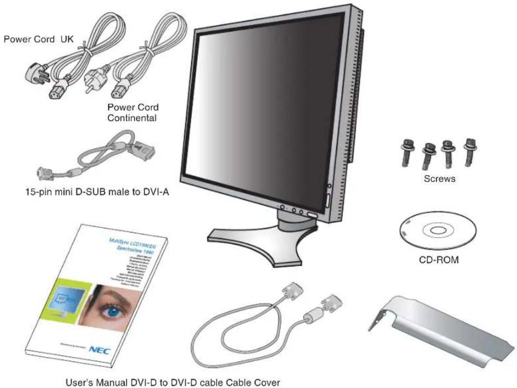
NOTE: This monitor can be equipped with optional loudspeakers: "MultiSync Sound bar". Please ask your dealer or check our website http://www.nec-display-solutions.com
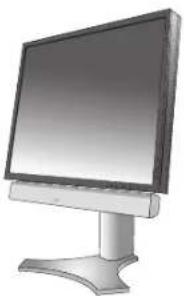
natural_image
Illustration of a flat-screen computer monitor with a stand (no text or symbols visible)* Remember to save your original box and packing material to transport or ship the monitor.
Quick Start
To attach the LCD monitor to your system, follow these instructions:
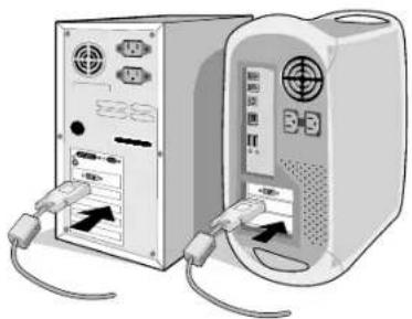
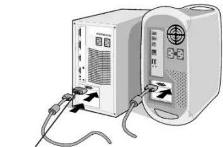
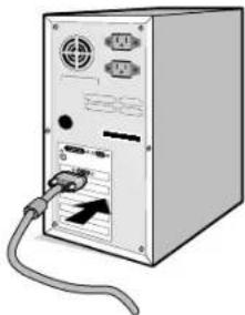
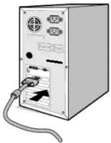
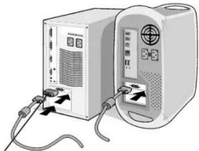
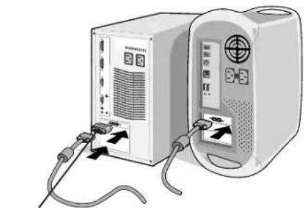
- Turn off the power to your computer.
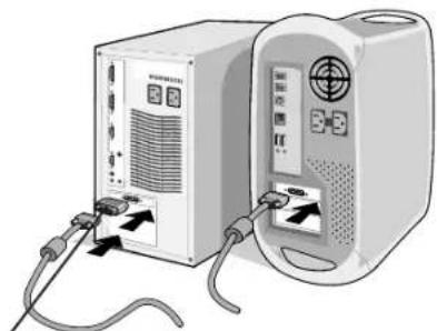
- For the PC or MAC with DVI digital output: Connect the DVI signal cable to the connector of the display card in your system (Figure A.1). Tighten all screws.
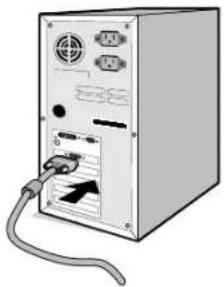
For the PC with Analog output: Connect the 15-pin mini D-SUB to DVI-A signal cable to the connector of the display card in your system (Figure A.2).
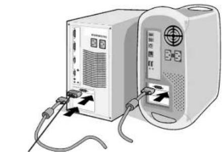
For the MAC: Connect the Macintosh cable adapter to the computer, then attach the 15-pin mini D-SUB signal cable to the Macintosh cable adapter (Figure B.1).
natural_image
Two computer units connected by cables, one with ports and arrows indicating data transfer (no visible text or symbols)Figure A.1 Figure B.1
natural_image
Front view of a computer tower with attached cables and ports (no visible text or labels)Figure A.2
natural_image
Illustration of two connected devices with cables and ports, no visible text or symbolsMacintosh Cable Adapter (not included)
NOTE: Some Macintosh systems do not require a Macintosh cable adapter.
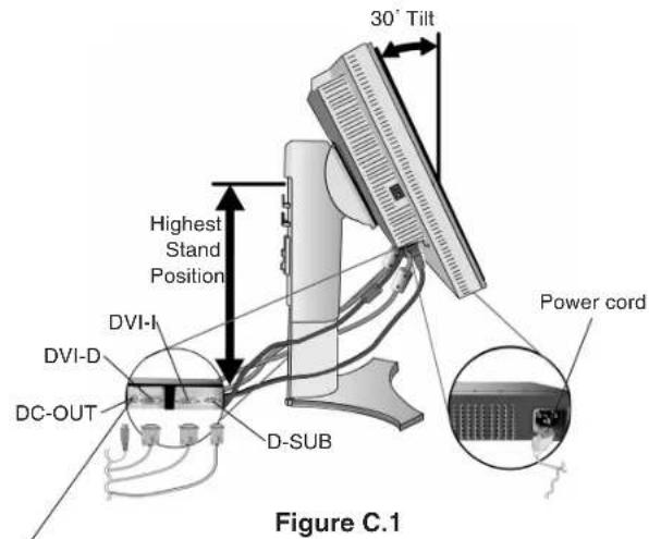
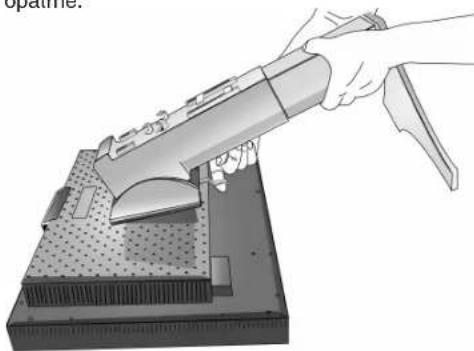
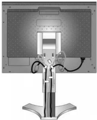
- Place hands on each side of the monitor to tilt the LCD panel 30-degree angle and lift up to the highest position (Figure C.1).
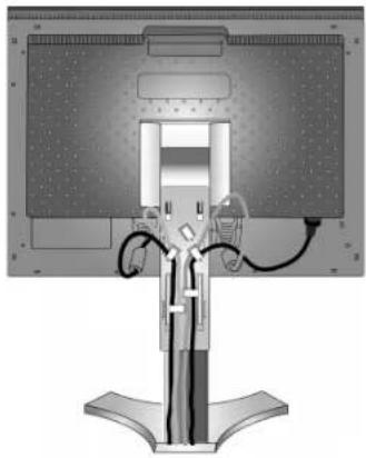
- Connect all cables to the appropriate connectors (Figure C.1).
NOTE: Incorrect cable connections may result in irregular operation, damage display quality/components of LCD module and/or shorten the module's life.
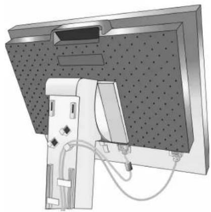
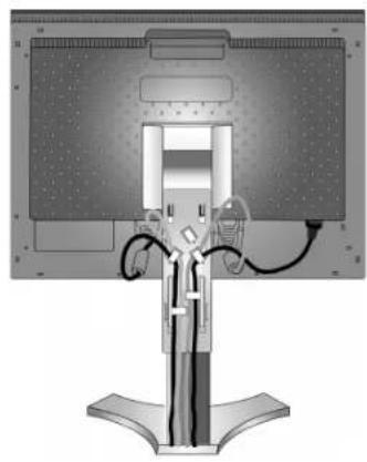
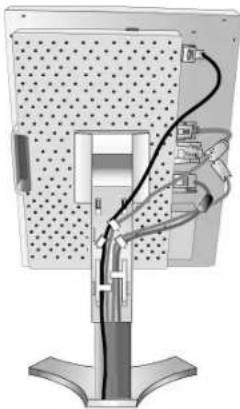
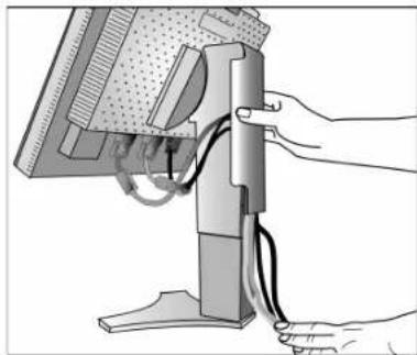
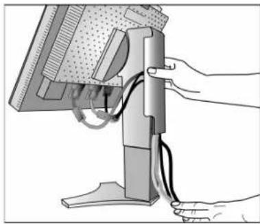
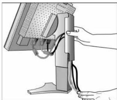
- To keep the cables neatly organized, place them into the cable management system that is built into the stand.
Place the D-Sub cable (not included) and the power cable into the specific hooks as indicated (Figure C.2).
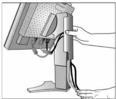
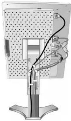
Place the DVI cable and the 15-pin mini D-Sub to DVI-A cable into the hooks as indicated (Figure C.3).
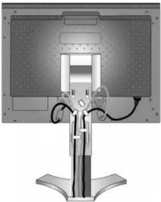
When using the monitor in Portrait mode, place the DVI cable and the 15-pin mini D-Sub to DVI-A cable into the hooks as indicated (Figure C.4).
- Make sure all cables are resting flat against the stand (Figure C.3).
Please check Tilt, Rise and Lower monitor screen and screen rotation when you manage cables.
NEC optional product attachment. Do not use this connector unless specified.
natural_image
Technical illustration of a mechanical assembly with a mounted component and wiring (no text or symbols visible)Figure C.2

natural_image
Diagram of a computer monitor with cable and stand (no text or symbols visible)Figure C.3

natural_image
Diagram of a computer monitor with cable and port connections (no text or symbols)Figure C.4
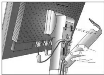
- Hold all cables firmly and place the cable cover onto the stand (Figure D.1). To remove the cable cover, lift the cover off as shown in Figure D.2.
- Connect one end of the power cord to the AC inlet on the back of the monitor and the other end to the power outlet.
NOTE: Please refer to Caution section of this manual for proper selection of AC power cord.
natural_image
Illustration of a hand operating a mechanical device with a tool, no visible text or symbolsFigure D.1
natural_image
Illustration of hands connecting cables to a computer monitor (no text or symbols visible)Figure D.2
- The Vacation Switch on the left side of the monitor must be turned on. Turn on the monitor with the front power button (Figure E.1) and the computer.
NOTE: The Vacation Switch is a true on/off switch. If this switch is on the OFF position, the monitor cannot be turned on using the front button. DO NOT switch on/off repeatedly.
- No-touch auto adjust automatically adjusts the monitor to optimal settings upon initial setup for most timings. For further adjustments, use the following OSM controls:
• Auto Contrast (Analog input only)
• Auto Adjust (Analog input only)
Refer to the Controls section of this User's Manual for a full description of these OSM controls.
NOTE: If you have any problems, please refer to the Troubleshooting section of this User's Manual.
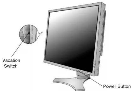
Figure E.1
English-4
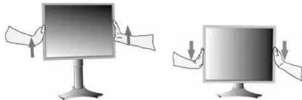
Raise and Lower Monitor Screen
The monitor may be raised or lowered in either Portrait or Landscape mode.
To raise or lower screen, place hands on each side of the monitor and lift or lower to the desired height (Figure RL.1).
NOTE: Handle with care when raising or lowering the monitor screen.
natural_image
Two illustrations of hands holding a computer monitor, one with an upward arrow and the other with downward arrows (no text or symbols)Figure RL.1
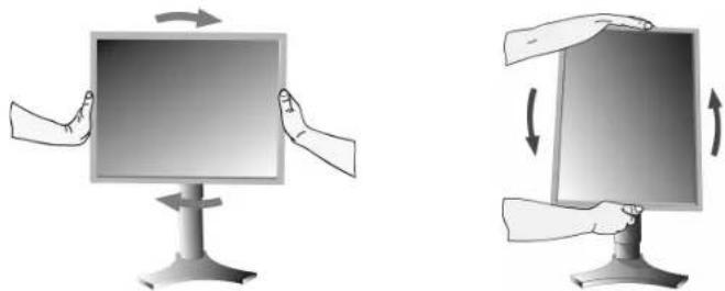
Screen Rotation
Before rotating, the screen must be raised to the highest level to avoid knocking the screen on the desk or pinching with your fingers.
To raise the screen, place hands on each side of the monitor and lift up to the highest position (Figure RL.1).
To rotate screen, place hands on each side of the monitor screen and turn clockwise from Landscape to Portrait or counterclockwise from Portrait to Landscape (Figure R.1).
To rotate OSM menu between landscape and portrait, refer to "Controls" section.
natural_image
Two illustrations of a computer monitor with hands, showing left and right rotation (no text or symbols)Figure R.1
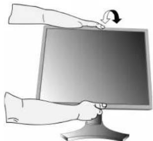
Tilt
Grasp top and bottom sides of the monitor screen with your hands and adjust the tilt as desired (Figure TS.1).
natural_image
Illustration of a hand pressing down on a computer monitor with a scroll arrow (no text or symbols)Figure TS.1
NOTE: Handle with care when tilting the monitor screen.
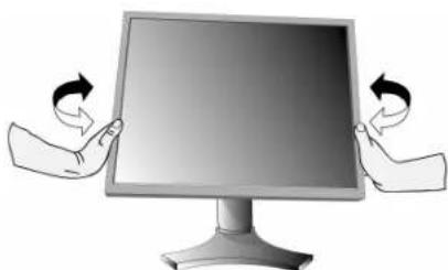
Swivel
Grasp both sides of the monitor screen with your hands and adjust the swivel as desired (Figure TS.2).

natural_image
Illustration of two hands holding a computer monitor with arrows indicating rotation (no text or symbols)Figure TS.2
English-5
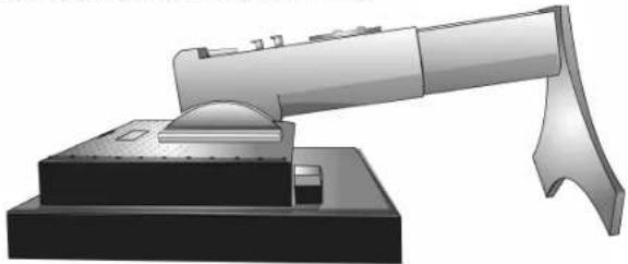
Remove Monitor Stand for Mounting
To prepare the monitor for alternate mounting purposes:
- Disconnect all cables.
- Place hands on each side of the monitor and lift up to the highest position.
- Place monitor face down on a non-abrasive surface (Figure S.1).
natural_image
3D rendering of a robotic arm with a curved handle and base platform (no text or symbols visible)Figure S.1
- Place one hand around the base and one hand on the Quick Release Lever. Move the Quick Release Lever in the direction indicated by the arrows (Figure S.2).
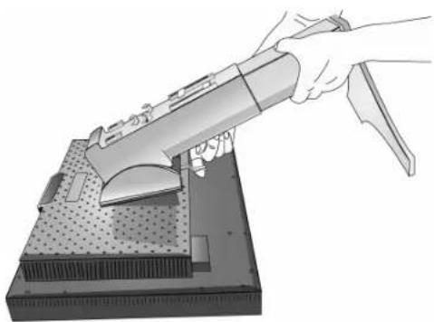
- Lift up the bottom of the stand to unhook it from the monitor (Figure S.3). The monitor can now be mounted using and alternate method. Reverse process to reattach stand.
NOTE: Use only VESA-compatible alternative mounting method (100 mm pitch).
NOTE: Handle with care when removing monitor stand.
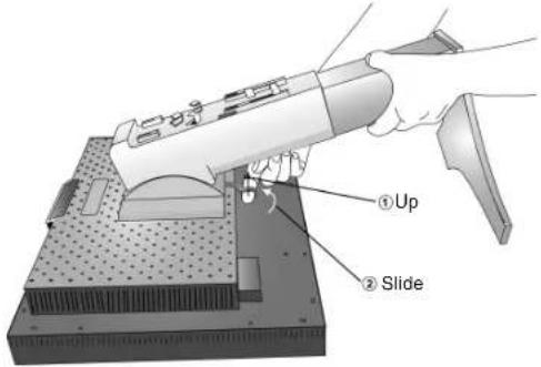
Figure S.2
natural_image
Illustration of a hand using a tool to clean or inspect a mechanical component (no text or symbols visible)Figure S.3
Flexible Arm Installation
This LCD monitor is designed for use with a flexible arm.
- Follow the instructions on how Remove Monitor Stand for Mounting to remove the stand.
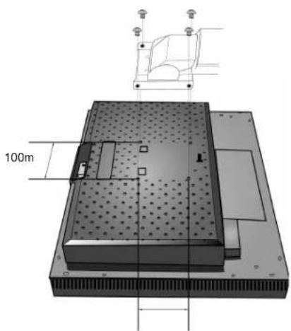
- Using the 4 screws from the stand removal and attach the arm to the monitor (Figure F.1).
Caution: Use ONLY the screws (4 pcs) that are included when mounting to avoid damage to the monitor and stand. To fulfil the safety requirements the monitor must be mounted to an arm which guarantees the necessary stability under consideration of the weight of the monitor. The LCD monitor should only be used with an approved arm (e.g. GS mark).
natural_image
Technical diagram of a mechanical assembly with 100m measurement annotation and component outline (no readable text or symbols)Figure F.1
English-6
Controls
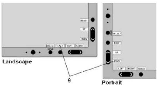
OSM (On-Screen Manager) control buttons on the front of the monitor function as follows:
To access OSM menu, press any of the control buttons (EXIT, LEFT, RIGHT, UP, DOWN). To change signal input, press the SELECT button.
NOTE: OSM must be closed in order to change signal input.
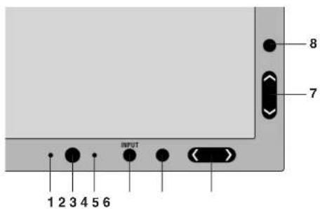
| 1 Ambibright Sensor | Detects the level of ambient lighting allowing the monitor to make adjustments to various settings resulting in a more comfortable viewing experience. Do not cover this sensor. |
| 2 Power | Turns the monitor on and off. |
| 3 LED | Indicates that the power is on.Can be changed between blue and green in the Advanced OSM Control menu. |
| 4 INPUT/SELECT | Enters the OSM Control menu. Enters OSM sub menus.Changes the input source when not in the OSM Control menu. |
| 5 EXIT | Exits the OSM sub menu. Exits OSM Control menu. |
| 6 LEFT/RIGHT | Navigates to the left or right through the OSM Control menu. |
| 7 UP/DOWN | Navigates up or down through the OSM Control menu. |
| 8 RESET/ROTATE OSM | Resets the OSM back to factory settings.When pressed when the OSM is not showing, rotates the OSM Control menu between portrait and landscape mode (Refer to CD-ROM version Page 22, Tag9 “OSM ROTATION”).* |
| 9 KEY GUIDE | The Key Guide appears on screen when the OSM control menu is accessed.The Key Guide will rotate when the OSM control menu is rotated. |
* The "LEFT/RIGHT" and "UP/DOWN" buttons functionality is interchangeable depending on the orientation (landscape/portrait) of the OSM.

Brightness/Contrast Controls
BRIGHTNESS
Adjusts the overall image and background screen brightness.
CONTRAST
Adjusts the image brightness in relation to the background.
AUTO CONTRAST (Analog input only)
Adjusts the image displayed for non-standard video inputs.
ECO MODE
Decreases the amount of power consumed by reducing the brightness level.
1: Decreases the brightness by 25%.
2: Decreases the brightness by 50%.
CUSTOM: Decreases the brightness level as determined by the user.
Refer to the Advanced OSM menu for custom setting instructions.
AUTO BRIGHTNESS
There are three settings for Auto Brightness.
OFF: No function.
1: Adjusts the brightness automatically, by detecting the brightness level of your environment and adjusting the monitor with the best BRIGHTNESS setting ^*1 .
2: Adjusts the brightness automatically for the best BRIGHTNESS setting based on the white display area. The environmental brightness sensor (Ambibright sensor) has no function.
NOTE: Do not cover environmental brightness sensor (Ambibright sensor).
*1: Please refer to Page 24 (CD-ROM Version) for full "Auto Brightness" information.
BLACK LEVEL
Adjust the black level.

Auto Adjust (Analog input only)
Automatically adjusts the Image Position and H. Size settings and Fine settings.

Image Controls
LEFT / RIGHT
Controls Horizontal Image Position within the display area of the LCD.
DOWN / UP
Controls Vertical Image Position within the display area of the LCD.
H.SIZE (V.SIZE) (Analog input only)
Adjusts the horizontal size by increasing or decreasing this setting.
If the "AUTO Adjust function" do not give you a satisfactory picture setting, a further tuning can be performed using the "H.Size (or V.Size)" function (dot clock). For this a Moiré test pattern could be used. This function may alter the width of the picture. Use Left/Right Menu to center the image on the screen. If the H.Size (or V.Size) is wrongly calibrated, the result would look like on the left drawing. The image should be homogeneous.
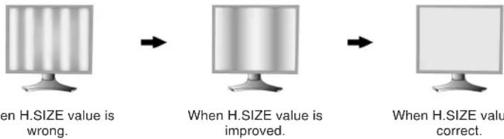
flowchart
graph LR
    A["When H.SIZE value is wrong."] --> B["When H.SIZE value is improved."]
    B --> C["When H.SIZE value correct."]
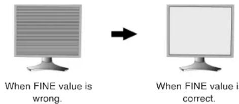
FINE (Analog input only)
Improves focus, clarity and image stability by increasing or decreasing this setting.
If the "Auto Adjust function" and the "H.Size" function do not give you a satisfactory picture setting, a fine tuning can be performed using the "Fine" function.
For this a Moiré test pattern could be used. If the Fine value is wrongly calibrated, the result would look like on the left drawing. The image should be homogeneous.
English-8
AUTO FINE (Analog input only)
This function automatically and periodically adjusts the "FINE" setting for change in signal condition. This function adjusts approximately every 33 minutes or when a change in signal timing is detected.
EXPANSION
Sets the zoom method.
FULL: The image is expanded to 1280 x 1024, regardless of the resolution.
ASPECT: The image is expanded without changing the aspect ratio.
OFF: The image is not expanded.
CUSTOM: Refer to the ADVANCED OSM Controls menu section of the user's manual for detailed instructions.

Color Control Systems
Colour Control Systems: Seven colour presets select the desired colour setting (sRGB, NATIVE and PROGRAMMABLE colour presets are standard and cannot be changed).
1, 2, 3 and 5: Increases or decreases Colour temperature, Red, Yellow, Green, Cyan, Blue, Magenta depending upon which is selected. The change in colour will appear on screen and the direction (increase or decrease) will be shown by the colour bars.
NATIVE, sRGB: Original colour presented by the LCD panel that is unadjustable.
PROGRAMMABLE: The colour tone that was set up with the downloaded application software is reflected.
NOTE: To reset a poor image setting, turn on the monitor by using front power button while holding "EXIT" and "SELECT" buttons at the same time.

Tools 1
SHARPNESS
This function is digitally capable to keep crisp image at any timings. It is continuously adjustable to get distinct image or soft one as you prefer, and set independently by different timings.
DVI SELECTION
This function selects the DVI input mode (DVI-I). When the DVI selection has been changed, the computer has to be restarted.
AUTO: By using the DVI-D to DVI-D cable, the DVI SELECTION is DIGITAL. By using the D-SUB to DVI-A cable, the DVI SELECTION is ANALOG.
DIGITAL: DVI digital input is available.
ANALOG: DVI analog input is available.
NOTE: For the MAC with digital output: Before turning on the MAC, the DVI Input mode must be set to DIGITAL in "DVI SELECTION" of OSM by pressing "SELECT" button then "CONTROL" button when the DVI signal cable is connected to the DVI-I connector (DVI-I) of the monitor. Otherwise the MAC may not turn on.
NOTE: Depending on the PC and Video card used, or when another Video signal cable is attached, this function may not operate.
VIDEO DETECT
Selects the method of video detection when more than one computer is connected.
FIRST: The video input has to be switched to "FIRST" mode. When current video input signal is not present, then the monitor searches for a video signal from the other video input port. If the video signal is present in the other port, then the monitor switches the video source input port to the new found video source automatically. The monitor will not look for other video signals while the current video source is present.
LAST: The video input has to be switched to the "LAST" mode. When the monitor is displaying a signal from the current source and a new secondary source is supplied to the monitor, then the monitor will automatically switch to the new video source. When current video input signal is not present, then the monitor searches for a video signal from the other video input port. If the video signal is present in the other port, then the monitor switches the video source input port to the new found video source automatically.
NONE: The Monitor will not search the other video input port unless the monitor is turned on.
OFF TIMER
Monitor will automatically power-down when the end user has selected a pre-determined amount of time. Before powering off, a message will appear on the screen asking the user if they want to delay the turn off time by 60 minutes. Press any OSM button to delay the turn off time.
IPM
The Intelligent Power Manager allows the monitor to enter into a power saving mode after a period of inactivity. The IPM has three settings.
OFF: Monitor does not go into power save mode when the input signal is lost.
STANDARD: Monitor enters power save mode automatically when the input signal is lost.
OPTION: Monitor enters power save mode automatically when the amount of surrounding light goes below the level that is determined by the user. The level can be adjusted in Tag 7 of the Advanced OSM Control menu.
When in power save mode, the LED on the front of the monitor blinks amber. While in power save mode, push any of the front buttons, except for POWER and SELECT to return to normal.
When the amount of surrounding light returns to normal levels, the monitor will automatically return to normal mode.
COLORCOMP
This function electronically compensates for the slight variations in the white uniformity level, as well as for deviations in color that may occur throughout the display area of the screen. These variations are characteristic of LCD panel technology. This function improves the colour and evens out the luminance uniformity of the display.
NOTE: Using the COLORCOMP feature reduces the overall peak luminance of the display. If greater luminance is desired over the uniform performance of the display, then COLORCOMP should be turned off.

MENU Tools
LANGUAGE
OSM control menus are available in eight languages.
OSM LEFT/RIGHT
You can choose where you would like the OSM control image to appear on your screen. Selecting OSM Location allows you to manually adjust the position of the OSM control menu left or right.
OSM DOWN/UP
You can choose where you would like the OSM control image to appear on your screen. Selecting OSM Location allows you to manually adjust the position of the OSM control menu Up or Down.
OSM TURN OFF
The OSM control menu will stay on as long as it is use. In the OSM Turn Off submenu, you can select how long the monitor waits after the last touch of a button to shut off the OSM control menu. The preset choices are 10-120 seconds by 5 seconds step.
OSM LOCK OUT
This control completely locks out access to all OSM control functions. When attempting to activate OSM controls while in the Lock Out mode, a screen will appear indicating the OSM controls are locked out.
There are four types of OSM LOCK OUT:
OSM LOCK OUT with BRIGHTNESS and CONTRAST control: To activate the OSM Lock Out function, press SELECT, then "UP" button and hold down simultaneously. To deactivate the OSM Lock Out, press SELECT, then "UP" button and hold down simultaneously while in the OSM menu. BRIGHTNESS and CONTRAST can be adjusted while in the lock out mode.
OSM LOCK OUT with no control: To activate the OSM Lock Out function, press SELECT, then "Right" button and hold down simultaneously. To deactivate the OSM Lock Out, press SELECT, then "Right" button and hold down simultaneously while in the OSM menu. No controls can be adjusted while in the lock out mode.
OSM LOCK OUT with BRIGHTNESS (only) control: To activate the OSM Lock Out function, press SELECT, then "Down" and "Left" buttons and hold down simultaneously. To deactivate the OSM Lock Out, press SELECT, then "Down" and "Left" buttons and hold down simultaneously while in the OSM menu. BRIGHTNESS can be adjusted while in the lock out mode.
CUSTOM: Refer to the Advanced OSM Menu.
OSM TRANSPARENCY
Adjusts the transparency of the OSM Menu.
OSM COLOR
"Tag window frame color", "Item select color" and "Adjust window frame color" can be changed to Red, Green, Blue, or Gray.
RESOLUTION NOTIFIER
This optimal resolution is 1280 x 1024. If ON is selected, a message will appear on the screen after 30 seconds, notifying you that the resolution is not at 1280 x 1024.
HOT KEY
You can adjust the brightness and contrast directly. When this function is set to ON, you can adjust the brightness with "Left" or "Right", contrast with "Down" or "Up" buttons, while the OSM menu is off. The standard OSM can be accessed with the EXIT button.
FACTORY PRESET
Selecting Factory Preset allows you to reset all OSM control settings (BRIGHTNESS, CONTRAST, ECOMODE, AUTO BRIGHTNESS, BLACK LEVEL, IMAGE CONTROL, COLOR CONTROL SYSTEM, SHARPNESS, OFF TIMER, IPM, OSM LEFT/RIGHT, OSM UP/DOWN, OSM TURN OFF, OSM TRANSPARENCY) back to the factory settings. Individual settings can be reset by highlighting the control to be reset and pressing the RESET button.

Information
Provides information about the current resolution display and technical data including the preset timing being used and the horizontal and vertical frequencies. Indicates the model and serial numbers of your monitor.
OSM Warning
OSM Warning menus disappear with Exit button.
NO SIGNAL: This function gives a warning when there is no Horizontal or Vertical Sync. After power is turned on or when there is a change of input signal, the No Signal window will appear.
RESOLUTION NOTIFIER: This function gives a warning of use with optimized resolution. After power is turned on or when there is a change of input signal or the video signal doesn't have proper resolution, the Resolution Notifier window will open. This function can be disabled in the TOOL menu.
OUT OF RANGE: This function gives a recommendation of the optimized resolution and refresh rate. After the power is turned on or there is a change of input signal or the video signal doesn't have proper timing, the Out Of Range menu will appear.
NOTE: If "i CHANGE DVI SELECTION" is displayed, switch to DVI SELECTION.
For advanced user menu see "Appendix".
Recommended use
Safety Precautions and Maintenance

FOR OPTIMUM PERFORMANCE, PLEASE NOTE THE FOLLOWING WHEN SETTING UP AND USING THE LCD COLOUR MONITOR:

- DO NOT OPEN THE MONITOR. There are no user serviceable parts inside and opening or removing covers may expose you to dangerous shock hazards or other risks. Refer all servicing to qualified service personnel.
- Do not spill any liquids into the cabinet or use your monitor near water.
- Do not insert objects of any kind into the cabinet slots, as they may touch dangerous voltage points, which can be harmful or fatal or may cause electric shock, fire or equipment failure.
- Do not place any heavy objects on the power cord. Damage to the cord may cause shock or fire.
- Do not place this product on a sloping or unstable cart, stand or table, as the monitor may fall, causing serious damage to the monitor.
- Do not place any objects onto the monitor and do not use the monitor outdoors.
- The inside of the fluorescent tube located within the LCD monitor contains mercury. Please follow the bylaws or rules of your municipality to dispose of the tube properly.
- Do not bend power cord.
- Do not use monitor in high temperatured, humid, dusty, or oily areas.
- Do not cover vent on monitor.
- If monitor or glass is broken, do not come in contact with the liquid crystal and handle with care.
Immediately unplug your monitor from the wall outlet and refer servicing to qualified service personnel under the following conditions:
- When the power supply cord or plug is damaged.
- If liquid has been spilled, or objects have fallen into the monitor.
- If the monitor has been exposed to rain or water.
- If the monitor has been dropped or the cabinet damaged.
- If the monitor does not operate normally by following operating instructions.

CAUTION
- Allow adequate ventilation around the monitor so that heat can properly dissipate. Do not block ventilated openings or place the monitor near a radiator or other heat sources. Do not put anything on top of monitor.
- The power cable connector is the primary means of detaching the system from the power supply. The monitor should be installed close to a power outlet which is easily accessible.
- Handle with care when transporting. Save packaging for transporting.
Image Persistence: Image persistence is when a residual or "ghost" image of a previous image remains visible on the screen. Unlike CRT monitors, LCD monitors' image persistence is not permanent, but constant images being displayed for a long period of time should be avoided.
To alleviate image persistence, turn off the monitor for as long as the previous image was displayed. For example, if an image was on the monitor for one hour and a residual image remains, the monitor should be turned off for one hour to erase the image.
NOTE: As with all personal display devices, NEC DISPLAY SOLUTIONS recommends using a moving screen saver at regular intervals whenever the screen is idle or turning off the monitor when not in use.

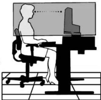
CORRECT PLACEMENT AND ADJUSTMENT OF THE MONITOR CAN REDUCE EYE, SHOULDER AND NECK FATIGUE. CHECK THE FOLLOWING WHEN YOU POSITION THE MONITOR:

- For optimum performance, allow 20 minutes for warm-up.
- Adjust the monitor height so that the top of the screen is at or slightly below eye level. Your eyes should look slightly downward when viewing the middle of the screen.
- Position your monitor no closer than 40 cm and no further away than 70 cm from your eyes. The optimal distance is 50 cm.
- Rest your eyes periodically by focusing on an object at least 20 feet away. Blink often.
- Position the monitor at a 90° angle to windows and other light sources to minimize glare and reflections. Adjust the monitor tilt so that ceiling lights do not reflect on your screen.
• If reflected light makes it hard for you to see your screen, use an anti-glare filter. - Clean the LCD monitor surface with a lint-free, non-abrasive cloth. Avoid using any cleaning solution or glass cleaner!
- Adjust the monitor's brightness and contrast controls to enhance readability.
- Use a document holder placed close to the screen.
- Position whatever you are looking at most of the time (the screen or reference material) directly in front of you to minimize turning your head while you are typing.
- Avoid displaying fixed patterns on the monitor for long periods of time to avoid image persistence (after-image effects).
- Get regular eye checkups.
natural_image
Silhouette of a person sitting at a desk with a computer, no text or symbols visibleErgonomics
To realize the maximum ergonomics benefits, we recommend the following:
- Adjust the Brightness until the background raster disappears.
- Do not position the Contrast control to its maximum setting.
- Use the preset Size and Position controls with standard signals.
- Use the preset Colour Setting.
- Use non-interlaced signals with a vertical refresh rate more than 60 Hz.
- Do not use primary colour blue on a dark background, as it is difficult to see and may produce eye fatigue to insufficient contrast.
Cleaning the LCD Panel
- When the liquid crystal panel is stained with dust or dirt, please wipe with soft cloth gently.
- Please do not rub the LCD panel with hard material.
- Please do not apply pressure to the LCD surface.
- Please do not use OA cleaner it will cause deterioration or discolor on the LCD surface.
Cleaning the Cabinet
- Unplug the power supply
• Gently wipe the cabinet with a soft cloth
• To clean the cabinet, dampen the cloth with a neutral detergent and water, wipe the cabinet and follow with a dry cloth.
NOTE: Many plastics are used on the surface of the cabinet. DO NOT clean with benzene, thinner, alkaline detergent, alcoholic system detergent, glass cleaner, wax, polish cleaner, soap powder, or insecticide. Do not touch rubber or vinyl to the cabinet for a long time. These types of fluids and fabrics can cause the paint to deteriorate, crack or peel.


English-14


VAROVÁNÍ

CHRAŃTE ZAŘÍZENÍ PŘED DEŠTĚM A VLHKEM. ZABRÁNÍTE TAK NEBEZPEČÍ POŽÁRU NEBO ÚRAZU ELEKTRICKÝM PROUDEM. POLARIZOVANOU ZÁSTRČKU JEDNOTKY NEPOUŽÍVEJTE VE SPOJENÍ SE ZÁSUVKOU PRODLUŽOVACÍ ŠNŮRY NEBO JINÝMI ZÁSUVKAMI, POKUD KOLÍKY NELZE ZCELA ZASUNOUT.
UVNITŘ ZAŘÍZENÍ SE NACHÁZÍ VYSOKONAPĚTOVĚ KOMPONENTY, PROTO SKŘÍŇ NEOTEVÍREJTE. SERVIS SVĚRĚTE KVALIFIKOVANÉ OSOBĚ.

UPOZORNĚNÍ

UPOZORNĚNÍ: PRO SNÍŽENÍ RIZIKA ÚRAZU ELEKTRICKÝM PROUDEM ZKONTROLUJTE, ZDA JE NAPÁJECÍ ŠNŮRA ODPOJENA ZE ZÁSUVKY. PRO ÚPLNÉ ODPOJENÍ ZDROJE NAPÁJENÍ OD JEDNOTKY ODPOJTE NAPÁJECÍ ŠNŮRU Z ELEKTRICKÉ ZÁSUVKY (NEOSTRAŇUJTE KRYT). UVNITŘ SE NENACHÁZEJÍ DÍLY, DO KTERÝCH UŽIVATEL MŮŽE ZASAHOVAT. SERVIS SVĚRTE KVALIFIKOVANÉ OSOBĚ.

NEC Display Solutions, Ltd.
4-13-23, Shibaura,
Minato-Ku
Tokyo 108-0023, Japan

ISO 13406-2

natural_image
Illustration of a flat-screen computer monitor with a stand (no text or symbols visible)Rychlý start
natural_image
Two computer units connected by cable, one with ports and arrows indicating connection (no visible text or symbols)natural_image
Front view of a computer tower with attached cable and ports (no visible text or labels)Obrázek A.2

natural_image
Illustration of two electronic devices connected by cables, one with ports and cable connectors (no visible text or symbols)natural_image
Technical illustration of a computer monitor with wiring and connectors, no visible text or symbolsObrázek C.2
Česky-3
natural_image
Diagram of a computer monitor with cable and stand (no text or symbols)Obrázek C.3

natural_image
Diagram of a computer monitor with cable and connector, showing internal components (no text or symbols)Obrázek C.4
natural_image
Diagram of a hand operating a mechanical device with wires and components, no visible text or symbolsObrázek D.1

natural_image
Illustration of a computer monitor with cable being inserted, showing hands interacting with the screen (no text or symbols present)Obrázek D.2
natural_image
Two illustrations of a computer monitor with arrows indicating direction (no text or symbols)Obrázek RL.1

Otočení obrazovky
natural_image
Two illustrations showing a computer monitor with arrows indicating rotation or movement (no text or symbols present)Obrázek R.1
Sklon monitoru
natural_image
Illustration of a hand pressing down on a computer monitor with a scroll arrow (no text or symbols)Obrázek TS.1
Otáčení
natural_image
Illustration of two hands interacting with a computer monitor (no text or symbols)Obrázek TS.2
natural_image
3D rendering of a mechanical device with a cylindrical component and a base, no visible text or symbolsObrázek S.1
Obrázek S.2
natural_image
Illustration of a hand using a tool to cut a mechanical component on a workbench (no text or symbols visible)Obrázek S.3
natural_image
Silhouette of a person sitting at a desk with a computer, no text or symbols visible
Ergonomika
NEC Display Solutions, Ltd.
4-13-23, Shibaura,
Minato-Ku
Tokyo 108-0023, Japan
natural_image
Illustration of a computer monitor with a blank screen and stand (no text or symbols)natural_image
Two computer units connected by cables, one with ports and arrows indicating data transfer (no visible text or symbols)natural_image
Front view of a computer tower with power cord and cable (no visible text or labels)Abbildung A.2
natural_image
Illustration of two electronic devices connected by cables, one with ports and cable connectors (no visible text or symbols)natural_image
Technical illustration of a mechanical assembly with a mounted device and wiring, no visible text or symbolsAbbildung C.2
Deutsch-3
natural_image
Diagram of a computer monitor with cable and stand (no text or symbols visible)Abbildung C.3
natural_image
Diagram of a computer monitor with cable and connector, showing internal components (no text or symbols)Abbildung C.4
natural_image
Mechanical assembly diagram showing a hand operating a tool with a caliper and attached components (no text or symbols visible)Abbildung D.1

natural_image
Illustration of hands connecting cables to a computer monitor (no text or symbols visible)Abbildung D.2
natural_image
Two illustrations of hands holding a computer monitor, one with an upward arrow and the other with downward arrows (no text or symbols)Abbildung RL.1
Bildschirmdrehung
natural_image
Illustration of two computer monitors with hands holding and rotating, showing directional arrows (no text or symbols)Abbildung R.1
Neigen
natural_image
Illustration of a hand pressing down on a computer monitor with an arrow indicating rotation (no text or symbols present)Abbildung TS.1
natural_image
Illustration of two hands interacting with a computer monitor (no text or symbols)Abbildung TS.2
Deutsch-5
natural_image
3D rendering of a robotic arm with a curved handle and base platform (no text or symbols visible)Abbildung S.1
natural_image
Illustration of a hand using a tool to cut a metal component on a workbench (no text or symbols visible)Abbildung S.3
natural_image
Silhouette of a person sitting at a desk with a computer, no text or symbols presentErgonomie
NEC Display Solutions, Ltd.
4-13-23, Shibaura,
Minato-Ku
natural_image
Illustration of a flat-screen computer monitor with a stand (no text or symbols visible)natural_image
Two computer units connected by cables, one with ports and arrows indicating data transfer (no visible text or symbols)Σχήμα Α.1 Σχήμα Β.1
natural_image
Front view of a computer tower with power cord and cable (no visible text or labels)Σχήμα Α.2

natural_image
Two electronic devices connected by cables, one with a labeled card and ports, the other with a display (no visible text or symbols)natural_image
Technical illustration of a computer monitor with attached cable and sensor components (no text or symbols)Σχήμα Γ.2
Ελληνικά-3
natural_image
Diagram of a computer monitor with cable and stand (no text or symbols visible)Σχήμα Γ.3
natural_image
Diagram of a computer monitor with cable and connector, showing internal components (no text or symbols)Σχήμα Γ.4
natural_image
Mechanical assembly diagram showing a hand operating a tool with wires and components (no visible text or symbols)Σχήμα Δ.1

natural_image
Illustration of hands connecting cables to a computer monitor (no text or symbols visible)Σχήμα Δ.2
natural_image
Two illustrations of a computer monitor with arrows indicating direction (no text or symbols)Σχήμα ΡΛ.1
natural_image
Two illustrations showing a computer monitor with hand gestures, one with left-hand rule and the other with right-hand rule (no text or symbols)Σχήμα P.1
Ρύθμιση τησ κλίσησ
natural_image
Illustration of a hand pressing down on a computer monitor with an arrow indicating rotation (no text or symbols)Σχήμα ΤΣ.1
Περιστροφή
natural_image
Illustration of two hands interacting with a computer monitor (no text or symbols present)Σχήμα ΤΣ.2
natural_image
3D rendering of a mechanical assembly with a cylindrical component and base (no text or symbols visible)Σχήμα Σ.1
natural_image
Illustration of a hand using a tool to clean or prepare a mechanical component (no text or symbols visible)Σχήμα Σ.3
SHARPNESS (KAΘAPOTHTA)
natural_image
Silhouette of a person sitting at a desk with a computer, viewed from behind (no text or symbols)Directiva 89/336/CEE:
- EN 55022
- EN 61000-3-2
- EN 61000-3-3
- EN 55024
y lleva la marca

NEC Display Solutions, Ltd. 4-13-23, Shibaura, Minato-Ku
natural_image
Illustration of a flat-screen computer monitor with a stand (no text or symbols visible)natural_image
Two computer units connected by cable, one with ports and arrows indicating connection (no visible text or symbols)Figura A.1 Figura B.1
natural_image
Front view of a computer tower drive with cable and ports (no visible text or labels)Figura A.2

natural_image
Illustration of two connected devices with cables and ports, no visible text or symbolsnatural_image
Technical illustration of a computer monitor with wiring and sensor components (no text or symbols)Figura C.2
Español-3
natural_image
Diagram of a computer monitor with cable and stand (no text or symbols visible)Figura C.3

natural_image
Diagram of a computer monitor with cable and connector, showing internal components (no text or symbols)Figura C.4
natural_image
Mechanical assembly diagram showing a hand operating a tool with wires and components (no visible text or symbols)Figura D.1

natural_image
Illustration of hands connecting cables to a computer monitor (no text or symbols visible)Figura D.2
natural_image
Two illustrations of hands holding a computer monitor, one with an upward arrow and the other with downward arrows (no text or symbols)Figura RL.1
natural_image
Two illustrations showing a computer monitor with arrows indicating rotation or movement (no text or symbols present)Figura R.1
Inclinación
natural_image
Illustration of a hand pressing down on a computer monitor with a scroll icon (no text or symbols)Figura TS.1
natural_image
Illustration of two hands interacting with a computer monitor (no text or symbols)Figura TS.2
Español-5
natural_image
3D rendering of a mechanical assembly with a cylindrical component and base (no text or symbols visible)Figura S.1
natural_image
Illustration of a hand using a tool to cut a metal component on a workbench (no text or symbols visible)Figura S.3
natural_image
Silhouette of a person sitting at a desk with a computer, no text or symbols visibleErgonomía
NEC Display Solutions, Ltd.
4-13-23, Shibaura, Minato-Ku
Tokyo 108-0023, Japon

ISO 13406-2

natural_image
Illustration of a flat-screen computer monitor with a stand (no text or symbols visible)natural_image
Two computer units connected by cable, one with ports and arrows indicating signal or data transfer (no visible text or symbols)Figure A.1 Figure B.1

natural_image
Front view of a computer tower drive with cable and ports (no visible text or labels)Figure A.2
natural_image
Illustration of a computer setup with two connected devices, one showing ports and cables (no text or symbols visible)natural_image
3D technical illustration of a computer monitor with wiring and sensor components (no text or symbols)Figure C.2
Français-3

natural_image
Diagram of a computer monitor with visible internal components and cable connections (no text or symbols)Figure C.3

natural_image
Diagram of a computer monitor with cable and stand, showing internal components (no text or symbols)Figure C.4
natural_image
Mechanical assembly diagram showing a hand operating a tool with wires and components (no visible text or symbols)Figure D.1
natural_image
Illustration of hands connecting cables to a computer monitor (no text or symbols visible)Figure D.2
natural_image
Two illustrations of hands holding a computer monitor, one with upward arrows and the other with downward arrows (no text or symbols)Figure RL.1
Rotation de l'écran
natural_image
Two illustrations showing a computer monitor with arrows indicating rotation or movement (no text or symbols present)Figure R.1
Inclinaison
natural_image
Illustration of a hand holding a computer monitor with a scroll icon above it (no text or symbols)Figure TS.1
Pivotement
natural_image
Illustration of a computer monitor with two hands and curved arrows indicating rotation (no text or symbols)Figure TS.2
natural_image
3D rendering of a mechanical assembly with a cylindrical component and base (no text or symbols visible)Figure S.1
natural_image
Illustration of a hand using a tool to cut or apply a component on a workbench (no text or symbols visible)Figure S.3
Installation du bras flexible
natural_image
Silhouette of a person sitting at a desk in an office chair, facing a computer screen (no text or symbols visible)Ergonomie
NEC Display Solutions, Ltd.
4-13-23, Shibaura,
Minato-Ku
natural_image
Illustration of a computer monitor with a blank screen and stand (no text or symbols)natural_image
Two computer units connected by cable, one with ports and arrows indicating data transfer (no visible text or symbols)Figura A.1 Figura B.1

natural_image
Front view of a computer tower with attached cable and ports (no visible text or labels)Figura A.2

natural_image
Illustration of two connected devices with cables and connectors (no visible text or symbols)natural_image
3D technical illustration of a computer monitor with wiring and sensor components (no text or symbols)Figura C.2
Italiano-3

natural_image
Diagram of a computer monitor with cable and stand (no text or symbols visible)Figura C.3

natural_image
Diagram of a computer monitor with cable and connector, showing internal components (no text or symbols)Figura C.4
natural_image
Diagram of a computer monitor with cable and hand operating a handheld device (no text or symbols visible)Figura D.1
natural_image
Illustration of hands connecting cables to a computer monitor (no text or symbols visible)Figura D.2
natural_image
Two illustrations of a computer monitor with arrows indicating direction (no text or symbols)Figura RL.1
natural_image
Two illustrations showing a computer monitor with hands and arrows indicating rotation (no text or symbols)Figura R.1
Inclinazione
natural_image
Illustration of a hand pressing down on a computer monitor with a scroll arrow (no text or symbols)Figura TS.1
Rotazione
natural_image
Illustration of two hands interacting with a computer monitor (no text or symbols present)Figura TS.2
natural_image
3D rendering of a mechanical assembly with a cylindrical component and base (no text or symbols visible)Figura S.1
natural_image
Illustration of a hand using a tool to cut or apply a component on a workbench (no text or symbols visible)Figura S.3
flowchart
graph LR
    A["Computer monitor with 5 rows"] --> B["Computer monitor with 1 column"]
    B --> C["Computer monitor with 1 column"]
natural_image
Two computer monitors with blank screens, one showing a grid pattern and the other showing an arrow (no text or symbols)natural_image
Silhouette of a person sitting at a desk with a computer, no text or symbols visibleErgonomia
NEC Display Solutions, Ltd.
4-13-23, Shibaura,
Minato-Ku
Tokyo 108-0023, Japan

ISO 13406-2

natural_image
Illustration of a flat-screen computer monitor with a stand (no text or symbols visible)natural_image
Two computer units connected by cables, one with ports and cable connectors (no visible text or symbols)natural_image
Front view of a computer tower with attached cables and ports (no visible text or labels)Illustratie A.2

natural_image
Illustration of a computer setup with two connected devices, one front-mounted and one back-mounted, showing ports and cables (no text or symbols visible)natural_image
3D technical illustration of a mechanical assembly with wires and components, no visible text or symbolsIllustratie C.2
Nederlands-3

natural_image
Diagram of a computer monitor with cable and stand (no text or symbols visible)Illustratie C.3

natural_image
Diagram of a computer monitor with cable and connectors, no visible text or symbolsIllustratie C.4
natural_image
Mechanical assembly diagram showing a tool interacting with a mechanical component (no text or symbols visible)Illustratie D.1

natural_image
Illustration of hands connecting cables to a computer monitor (no text or symbols visible)Illustratie D.2
natural_image
Two illustrations of a computer monitor with hands holding arrows, showing front and side views (no text or symbols)Illustratie RL.1
Scherm roteren
natural_image
Two illustrations showing a computer monitor with arrows indicating rotation or change, no text or symbols present.Illustratie R.1
Kantelen
natural_image
Illustration of a hand pressing down on a computer monitor with an arrow indicating rotation (no text or symbols present)Illustratie TS.1
natural_image
Illustration of a computer monitor with two hands and curved arrows indicating rotation (no text or symbols)Illustratie TS.2
natural_image
3D rendering of a mechanical assembly with a cylindrical component and base (no text or symbols visible)Illustratie S.1
natural_image
Illustration of a hand using a tool to cut or apply a component on a textured base (no text or symbols visible)Illustratie S.3
Zwenkarm monteren
DOWN/UP (OMHOOG/OMLAAG)
SHARPNESS (SCHERPTE)
natural_image
Silhouette of a person sitting at a desk with a computer, no text or symbols visibleNEC Display Solutions, Ltd.
4-13-23, Shibaura,
Minato-Ku
Tokyo 108-0023, Japonia

ISO 13406-2

natural_image
Illustration of a computer monitor with a stand and curved legs (no text or symbols)natural_image
Two computer units connected by cables, one with ports and arrows indicating data transfer (no visible text or symbols)natural_image
Front view of a computer tower with attached cable and ports (no visible text or symbols)Rysunek A.2

natural_image
Illustration of a computer setup with two connected devices and cables (no visible text or symbols)natural_image
3D technical illustration of a mechanical assembly with wires and components, no visible text or symbolsRysunek C.2

natural_image
Diagram of a computer monitor with cable and stand, showing internal components (no text or symbols)Rysunek C.3

natural_image
Diagram of a computer monitor with cable and connector, no text or symbols presentRysunek C.4
natural_image
Mechanical assembly diagram showing a hand operating a tool with a tool handle, no visible text or symbolsRysunek D.1

natural_image
Illustration of hands connecting cables to a computer monitor (no text or symbols visible)Rysunek D.2
natural_image
Two illustrations of hands holding a computer monitor, one with an upward arrow and the other with downward arrows (no text or symbols)Rysunek RL.1
Obroty ekranu
natural_image
Illustration of two hands holding a computer monitor with an arrow indicating rotation (no text or symbols)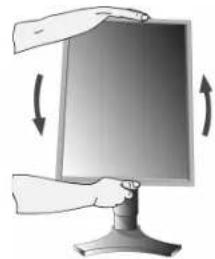
natural_image
Illustration of a hand holding a computer monitor with directional arrows indicating rotation (no text or symbols)Rysunek R.1
Pochylenie ekranu
natural_image
Illustration of a hand pressing down on a computer monitor with an arrow indicating rotation (no text or symbols present)Rysunek TS.1
Obrót ekranu
natural_image
Illustration of two hands holding a computer monitor with arrows indicating rotation (no text or symbols)Rysunek TS.2
natural_image
3D rendering of a robotic arm with a curved handle and base platform (no text or symbols visible)Rysunek S.1
natural_image
Illustration of a hand using a tool to clean or inspect a device on a workbench (no text or symbols visible)Rysunek S.3
DOWN/UP (POZYCJA PIONOWA)
natural_image
Silhouette of a person sitting at a desk with a computer, no text or symbols presentErgonomia
NEC Display Solutions, Ltd.
4-13-23, Shibaura,
Minato-Ku
Tokyo 108-0023, Japan

ME 06

ISO 13406-2

natural_image
Illustration of a flat-screen computer monitor with a stand (no text or symbols visible)natural_image
Two computer units connected by cable, one with ports and arrows indicating signal or data transfer (no visible text or symbols)natural_image
Front view of a computer tower with ports and cables (no visible text or labels)Рисунок А.2
natural_image
Illustration of two connected devices with cables and ports, no visible text or symbolsnatural_image
3D diagram of a computer monitor with attached circuit board and wiring (no text or symbols)natural_image
Diagram of a computer monitor with cable and stand (no text or symbols visible)Рисунок С.3

natural_image
Diagram of a computer monitor with cable and ventilation slots, no text or symbols presentРисунок С.4
natural_image
Mechanical assembly diagram showing a hand operating a tool with a tool handle, no visible text or symbolsРисунок D.1
natural_image
Illustration of hands connecting a computer monitor to a vertical cable or connector (no text or symbols visible)Рисунок D.2
natural_image
Illustration of a computer monitor with two arms pointing at it (no text or symbols)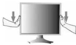
natural_image
Illustration of two hands holding a computer monitor with downward arrows indicating action (no text or symbols)Рисунок RL.1
Поворот экрана
natural_image
Illustration of two hands holding a computer monitor with an arrow indicating rotation (no text or symbols)
natural_image
Illustration of a computer monitor with an open lid and directional arrows indicating rotation (no text or symbols)Рисунок R.1
Наклон
natural_image
Illustration of a hand pressing down on a computer monitor with a scroll arrow (no text or symbols)Рисунок TS.1
natural_image
Illustration of two hands interacting with a computer monitor (no text or symbols)Рисунок TS.2
Русский-5
natural_image
3D rendering of a robotic arm with a curved handle and base platform (no text or symbols visible)Рисунок S.1
natural_image
Technical diagram of a mechanical assembly with labeled components and dimension lines (no readable text or symbols)Рисунок F.1
Органы управления
flowchart
graph LR
    A["Computer monitor with 5 vertical bars"] --> B["Computer monitor with 12 vertical bars"]
    B --> C["Computer monitor with blank space"]
natural_image
Two computer monitors, one with ventilation grilles and the other blank, shown in a transformation arrow (no text or symbols)natural_image
Silhouette of a person sitting at a desk with a computer, viewed from behind (no text or symbols)Эргономика
NEC Display Solutions, Ltd.
4-13-23, Shibaura,
Minato-Ku
Tokyo 108-0023, Japonya

ISO 13406-2

natural_image
Illustration of a computer monitor with a blank screen and stand (no text or symbols)natural_image
Two computer units connected by cable, one with ports and arrows indicating signal or data transfer (no visible text or symbols)Şekil A.1 Şekil B.1

natural_image
Front view of a computer tower drive with cable and ports (no visible text or labels)Şekil A.2
natural_image
Illustration of two connected devices with cables and ports, no visible text or symbolsnatural_image
Technical illustration of a computer monitor with wiring and sensor array (no text or symbols)Şekil C.2
Türkçe-3

natural_image
Diagram of a computer monitor with cable and stand (no text or symbols)Şekil C.3

natural_image
Diagram of a computer monitor with cable and connector, showing internal components (no text or symbols)Şekil C.4
natural_image
Technical illustration of a mechanical assembly with a hand operating a tool (no text or symbols visible)Şekil D.1

natural_image
Illustration of hands connecting a computer monitor to a vertical toolbar with cables (no text or symbols visible)Şekil D.2
natural_image
Two illustrations of hands holding a computer monitor, one with an upward arrow and the other with downward arrows (no text or symbols)Şekil RL.1
Ekranın Dönmesi
natural_image
Two illustrations showing a computer monitor with arrows indicating rotation or movement (no text or symbols present)Şekil R.1
Eğim
natural_image
Illustration of a hand pressing down on a computer monitor with an arrow indicating rotation (no text or symbols present)Şekil TS.1
natural_image
Illustration of two hands interacting with a computer monitor (no text or symbols)Şekil TS.2
Türkçe-5
natural_image
3D rendering of a mechanical assembly with a cylindrical component and base (no text or symbols visible)Şekil S.1
natural_image
Illustration of a hand using a tool to cut a metal component on a workbench (no text or symbols visible)Şekil S.3
Esnek Kol Montaji
flowchart
graph LR
    A["Screen Display"] --> B["Arrow to Screen Display"]
    B --> C["Arrow to Desktop Display"]
SHARPNESS (KESKİNLIK)
natural_image
Silhouette of a person sitting at a desk in an office chair, facing a computer screen (no text or symbols visible)Empowered by Innovation
NEC

Printed on recycled paper
Printed in China Part No. 1E504581


- MultiSync LCD1990SXi
- SpectraView 1990
- Canadian Department of Communications Compliance Statement
- FCC Information
- Declaration of Conformity
- TCO'03
- TCODevelopment
- Congratulations!
- Ergonomics
- Energy
- Emissions
- Ecology
- Manufacturer's Recycling and Energy Information
- Country-specific recycling programmes can also be found at:
- Disposing of your old NEC product
- Within the European Union
- Outside the European Union
- Index
- CAUTION
- Caution:
- Declaration
- Declaration of the Manufacturer
- Contents
- Quick Start
- Raise and Lower Monitor Screen
- Screen Rotation
- Tilt
- Swivel
- Remove Monitor Stand for Mounting
- Flexible Arm Installation
- Controls
- OSM (On-Screen Manager) control buttons on the front of the monitor function as follows:
- Brightness/Contrast Controls
- BRIGHTNESS
- CONTRAST
- AUTO CONTRAST (Analog input only)
- ECO MODE
- AUTO BRIGHTNESS
- BLACK LEVEL
- Auto Adjust (Analog input only)
- Image Controls
- LEFT / RIGHT
- DOWN / UP
- H.SIZE (V.SIZE) (Analog input only)
- FINE (Analog input only)
- AUTO FINE (Analog input only)
- EXPANSION
- Color Control Systems
- Tools 1
- SHARPNESS
- DVI SELECTION
- VIDEO DETECT
- OFF TIMER
- IPM
- COLORCOMP
- MENU Tools
- LANGUAGE
- OSM LEFT/RIGHT
- OSM DOWN/UP
- OSM TURN OFF
- OSM LOCK OUT
- OSM TRANSPARENCY
- OSM COLOR
- RESOLUTION NOTIFIER
- HOT KEY
- FACTORY PRESET
- Information
- OSM Warning
- Recommended use
- Safety Precautions and Maintenance
- FOR OPTIMUM PERFORMANCE, PLEASE NOTE THE FOLLOWING WHEN SETTING UP AND USING THE LCD COLOUR MONITOR:
- CORRECT PLACEMENT AND ADJUSTMENT OF THE MONITOR CAN REDUCE EYE, SHOULDER AND NECK FATIGUE. CHECK THE FOLLOWING WHEN YOU POSITION THE MONITOR:
- Cleaning the LCD Panel
- Cleaning the Cabinet
- VAROVÁNÍ
- UPOZORNĚNÍ
- Rychlý start
- Otočení obrazovky
- Sklon monitoru
- Otáčení
- Ergonomika
- Bildschirmdrehung
- Neigen
- Ergonomie
- Ρύθμιση τησ κλίσησ
- Περιστροφή
- SHARPNESS (KAΘAPOTHTA)
- Español-3
- Inclinación
- Ergonomía
- Français-3
- Rotation de l'écran
- Inclinaison
- Pivotement
- Installation du bras flexible
- Inclinazione
- Rotazione
- Ergonomia
- Nederlands-3
- Scherm roteren
- Kantelen
- Zwenkarm monteren
- DOWN/UP (OMHOOG/OMLAAG)
- SHARPNESS (SCHERPTE)
- Obroty ekranu
- Pochylenie ekranu
- Obrót ekranu
- DOWN/UP (POZYCJA PIONOWA)
- Поворот экрана
- Наклон
- Органы управления
- Эргономика
- Ekranın Dönmesi
- Eğim
- Esnek Kol Montaji
- SHARPNESS (KESKİNLIK)
- NEC
Brand : NEC
Model : SpectraView 1990p
Category : Monitor