
MultiSync LCD1560VM - Monitor NEC - Free user manual and instructions
Find the device manual for free MultiSync LCD1560VM NEC in PDF.

| Product Type | LCD Monitor |
| Brand | NEC |
| Model | MultiSync LCD1560VM |
| Screen Size | 15 inches (diagonal) |
| Optimal Resolution | 1024 x 768 |
| Weight (with stand) | 3.5 kg max |
| Power Supply | 220-240 V AC, 50/60 Hz |
| Connectors | VGA (D-Sub 15-pin), DVI (optional), audio input, headphone output |
| Adjustments | Tilt, raise/lower, rotate (pivot) |
| Display Functions | On-Screen Manager (OSM), auto adjustment, color control (RGB, sRGB, NATIVE) |
| Audio | Built-in speakers, headphone jack, mute |
| Maintenance | Soft, lint-free cloth, no liquid cleaner |
| Safety | Do not open the case, unplug if liquid spilled, use with approved cord |
| Standards | EN 60950, EN 55022, EN 61000-3-2, EN 61000-3-3, EN 55024; ENERGY STAR |
| Alternative Mounting | VESA compatible (75 x 75 mm), use with flexible arm (screws provided) |
| Included Accessories | Power cord, VGA video cable, audio cable, user manual, CD-ROM |
| Warranty | Consult the manual or dealer |
Frequently Asked Questions - MultiSync LCD1560VM NEC
User questions about MultiSync LCD1560VM NEC
0 question about this device. Answer the ones you know or ask your own.
Ask a new question about this device
Download the instructions for your Monitor in PDF format for free! Find your manual MultiSync LCD1560VM - NEC and take your electronic device back in hand. On this page are published all the documents necessary for the use of your device. MultiSync LCD1560VM by NEC.
USER MANUAL MultiSync LCD1560VM NEC
For the Customer to use in U.S.A. or Canada
Canadian Department of Communications Compliance Statement
DOC: This Class B digital apparatus meets all requirements of the Canadian Interference-Causing Equipment Regulations.
C-UL: Bears the C-UL Mark and is in compliance with Canadian Safety Regulations according to CSA C22.2 No. 950.
- Use the attached specified cables with the MultiSync LCD1560VM colour monitor so as not to interfere with radio and television reception.
(1) The power supply cord you use must have been approved by and comply with the safety standards of U.S.A., and meet the following condition.
| Power supply cord Non Length 2.0 m Plug shape | shield type, 3-conductor U.S.A |
(2) Shielded video signal cable. Use of other cables and adapters may cause interference with radio and television reception.
-
This equipment has been tested and found to comply with the limits for a Class B digital device, pursuant to part 15 of the FCC Rules. These limits are designed to provide reasonable protection against harmful interference in a residential installation. This equipment generates, uses, and can radiate radio frequency energy, and, if not installed and used in accordance with the instructions, may cause harmful interference to radio communications. However, there is no guarantee that interference will not occur in a particular installation. If this equipment does cause harmful interference to radio or television reception, which can be determined by turning the equipment off and on, the user is encouraged to try to correct the interference by one or more of the following measures:
-
Reorient or relocate the receiving antenna.
- Increase the separation between the equipment and receiver.
- Connect the equipment into an outlet on a circuit different from that to which the receiver is connected.
- Consult your dealer or an experienced radio/TV technician for help.
If necessary, the user should contact the dealer or an experienced radio/television technician for additional suggestions. The user may find the following booklet, prepared by the Federal Communications Commission, helpful: "How to Identify and Resolve Radio-TV Interference Problems." This booklet is available from the U.S. Government Printing Office, Washington, D.C., 20402, Stock No. 004-000-00345-4.
Declaration of Conformity
This device complies with Part 15 of FCC Rules. Operation is subject to the following two conditions. (1) This device may not cause harmful interference, and (2) this device must accept any interference received, including interference that may cause undesired operation.
U.S. Responsible Party: NEC-Mitsubishi Electronics Display of America, Inc. Address: 1250 N. Arlington Heights Road Itasca, Illinois 60143-1248
Tel. No.: (630) 467-3000
Type of Product: Display Monitor
Equipment Classification: Class B Peripheral
Model: MultiSync LCD1560VM

We hereby declare that the equipment specified above conforms to the technical standards as specified in the FCC Rules.
TCO'99
Congratulations! You have just purchased a TCO'99 approved and labeled product! Your choice has provided you with a product developed for professional use. Your purchase has also contributed to reducing the burden on the environment and also to the further development of environmentally adapted electronics products.

Why do we have environmentally labelled computers?
In many countries, environmental labelling has become an established method for encouraging the adaptation of goods and services to the environment. The main problem, as far as computers and other electronics equipment are concerned, is that environmentally harmful substances are used both in the products and during the manufacturing. Since it has not been possible for the majority of electronics equipment to be recycled in a satisfactory way, most of these potentially damaging substances sooner or later enter Nature.
There are also other characteristics of a computer, such as energy consumption levels, that are important from the viewpoints of both the work (Internal) and natural (external) environments. Since all methods of conventional electricity generation have a negative effect on the environment (acidic and climate-influencing emissions, radioactive waste, etc.), it is vital to conserve energy. Electronics equipment in offices consume an enormous amount of energy since they are often left running continuously.
What does labelling involve?
This product meets the requirements for the TCO'99 scheme which provides for international and environmental labelling of personal computers. The labelling scheme was developed as a joint effort by the TCO (The Swedish Confederation of Professional Employees), Svenska Naturskyddsforeningen (The Swedish Society for Nature Conservation) and Statens Energimyndighet (The Swedish National Energy Administration).
The requirements cover a wide range of issues: environment, ergonomics, usability, emission of electrical and magnetic fields, energy consumption and electrical and fire safety.
The environmental demands concern restrictions on the presence and use of heavy metals, brominated and chlorinated flame retardants, CFCs (freons) and chlorinated solvents, among other things. The product must be prepared for recycling and the manufacturer is obliged to have an environmental plan which must be adhered to in each country where the company implements its operational policy. The energy requirements include a demand that the computer and/or display, after a certain period of inactivity, shall reduce its power consumption to a lower level in one or more stages. The length of time to reactivate the computer shall be reasonable for the user.
Labelled products must meet strict environmental demands, for example, in respect of the reduction of electric and magnetic fields, physical and visual ergonomics and good usability.
Environmental Requirements
Flame retardants
Flame retardants are present in printed circuit boards, cables, wires, casings and housings. In turn, they delay the spread of fire. Up to thirty percent of the plastic in a computer casing can consist of flame retardant substances. Most flame retardants contain bromine or chloride and these are related to another group of environmental toxins, PCBs, which are suspected to give rise to severe health effects, including reproductive damage in fisheating birds and mammals, due to the bioaccumulative* processes. Flame retardants have been found in human blood and researchers fear that disturbances in foetus development may occur.
TCO'99 demand requires that plastic components weighing more than 25 grams must not contain flame retardants with organically bound chlorine and bromine. Flame retardants are allowed in the printed circuit boards since no substitutes are available.
Lead\*\*
Lead can be found in picture tubes, display screens, solders and capacitors. Lead damages the nervous system and in higher doses, causes lead poisoning.
TCO'99 requirement permits the inclusion of lead since no replacement has yet been developed.
Cadmium\*\*
Cadmium is present in rechargeable batteries and in the colour generating layers of certain computer displays. Cadmium damages the nervous system and is toxic in high doses.
TCO'99 requirement states that batteries, the colourgenerating layers of display screens and the electrical or electronics components must not contain any cadmium.
Mercury\*\*
Mercury is sometimes found in batteries, relays and switches, Mercury damages the nervous system and is toxic in high doses.
TCO'99 requirement states that batteries may not contain any Mercury. It also demands that no mercury is present in any of the electrical or electronics components associated with the display unit.
CFCs (freons)
CFCs (freons) are sometimes used for washing printed circuit boards. CFCs break down ozone and thereby damage the ozone layer in the stratosphere, causing increased reception on Earth of ultraviolet light with consequent increased risks of skin cancer (malignant melanoma).
The relevant TCO'99 requirement; Neither CFCs nor HCFCs may be used during the manufacturing and assembly of the product or its packaging.
*Bio-accumulative is defined as substances which accumulate within living organisms.
**Lead, Cadmium and Mercury are heavy metals which are Bio-accumulative.
To obtain complete information on the environmental criteria document, order from:
TCO Development Unit
SE-114 94 Stockholm
SWEDEN
FAX Number: +46 8 782 92 07
E-mail (Internet): development@tco.se
You may also obtain current information on TCO'99 approved and labelled products by visiting their website at:
http://www.tcodevelopment.com
Index
Warning, Caution ...... English-1
Declaration ...... English-1
Contents..... English-2
Quick Start ...... English-2
Controls..... English-6
Recommended use ...... English-9
TO PREVENT FIRE OR SHOCK HAZARDS, DO NOT EXPOSE THIS UNIT TO RAIN OR MOISTURE. ALSO, DO NOT USE THIS UNIT'S POLARIZED PLUG WITH AN EXTENSION CORD RECEPTACLE OR OTHER OUTLETS UNLESS THE PRONGS CAN BE FULLY INSERTED.
REFRAIN FROM OPENING THE CABINET AS THERE ARE HIGH VOLTAGE COMPONENTS INSIDE. REFER SERVICING TO QUALIFIED SERVICE PERSONNEL.

CAUTION

RISK OF ELECTRIC SHOCK • DO NOT OPEN
CAUTION: TO REDUCE THE RISK OF ELECTRIC SHOCK, DO NOT REMOVE COVER (OR BACK). NO USER SERVICEABLE PARTS INSIDE. REFER SERVICING TO QUALIFIED SERVICE PERSONNEL.

This symbol warns user that uninsulated voltage within the unit may have sufficient magnitude to cause electric shock. Therefore, it is dangerous to make any kind of contact with any part inside this unit.

This symbol alerts the user that important literature concerning the operation and maintenance of this unit has been included. Therefore, it should be read carefully in order to avoid any problems.
Caution:
When operating the MultiSync LCD1560VM with a 220-240V AC power source in Europe, use the power cord provided with the monitor.
In the UK, a BS approved power cord with a moulded plug has a Black (five Amps) fuse installed for use with this equipment. If a power cord is not supplied with this equipment please contact your supplier.
When operating the MultiSync LCD1560VM with a 220-240V AC power source in Australia, use the power cord provided with the monitor. If a power cord is not supplied with this equipment please contact your supplier.
For all other cases, use a power cord that matches the AC voltage of the power outlet and has been approved by and complies with the safety standard of your particular country.
Declaration
Declaration of the Manufacturer
We hereby certify that the colour monitor
MultiSync LCD1560VM (L152EM) is in compliance with
Council Directive 73/23/EEC: -EN 60950
Council Directive 89/336/EEC:
- EN 55022
- EN 61000-3-2
- EN 61000-3-3
- EN 55024
and marked with

NEC-Mitsubishi Electric Visual Systems, Corp.
MS Shibaura Bldg., 13-23, Shibaura 4-chome,
Minato-Ku, Tokyo 108-0023, Japan
ENERGY STAR is a U.S. registered mark.
As an ENERGY STAR ^® Partner, NEC-Mitsubishi Electronics Display of America, Inc. has determined that this product meets the ENERGY STAR guidelines for energy efficiency. The ENERGY STAR emblem does not represent EPA endorsement of any product or service.
IBM PC/XT/AT, PS/2, MCGA, VGA, 8514/A and XGA are registered trademarks of International Business Machines Corporation.
Apple and Macintosh are registered trademarks of Apple Computer Inc.
Microsoft and Windows are registered trademarks of the Microsoft Corporation.
NEC is a registered trademark of NEC Corporation.
All other trademarks or registered trademarks are property of their respective owners.
Contents
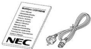
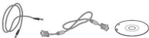
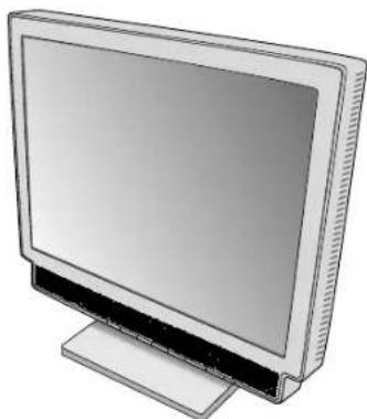
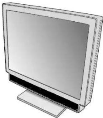
Your new NEC MultiSync LCD monitor box* should contain the following:
- MultiSync LCD1560VM monitor with tilt base
- Power Cord
• V ideo Signal Cable - Audio Cable
- User's Manual
- CD ROM (includes complete User's Manual in PDF format). Tosee the User's Manual, Acrobat Reader 4.0 must be installed on your PC.
User's Manual
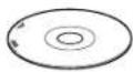
natural_image
Illustration of three electronic components: a coiled cable, connected cables with connectors, and a CD (no text or symbols)Power Cord
Audio Cable
Video Signal Cable
CD ROM
natural_image
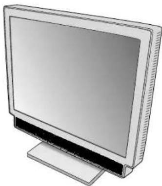
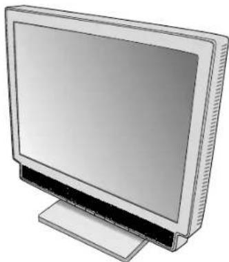
Illustration of a flat-screen computer monitor with a stand (no text or symbols visible)* Remember to save your original box and packing material to transport or ship the monitor.
Quick Start
Toattach the MultiSync LCD monitor to your system, follow these instructions:
- Turn off the power to your computer.
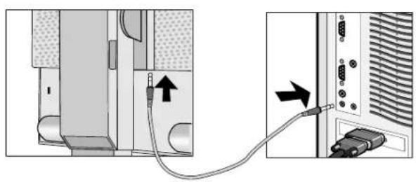
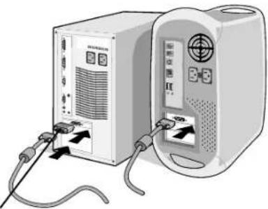
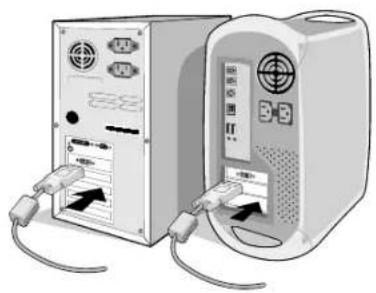
- Connect the audio cable to "AUDIO INPUT" on the back of the monitor and the other end to the "Audio out" terminal of the computer (Figure A.1).
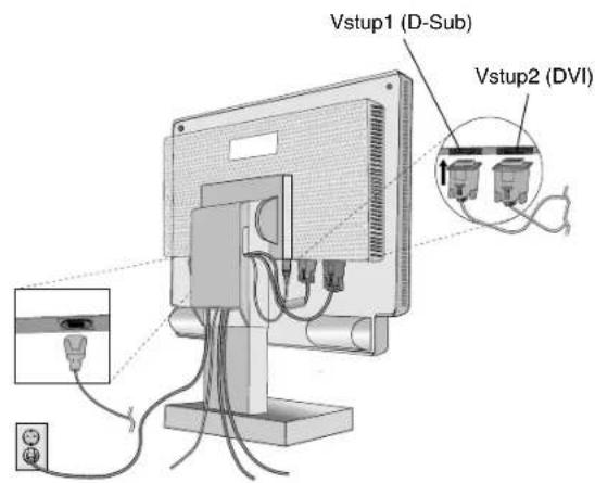
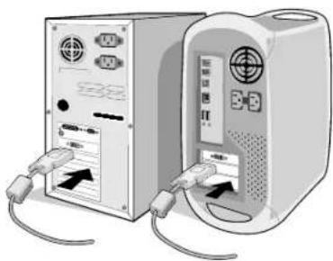
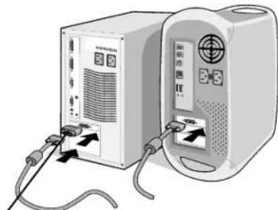
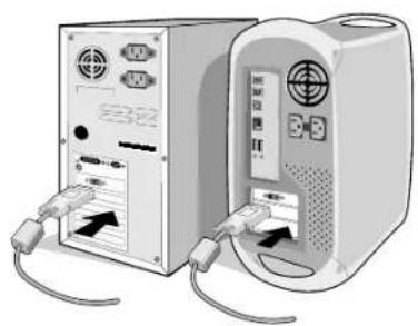
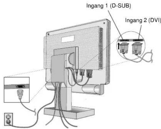
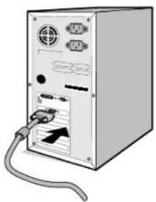
- For the PC or MAC with DVI digital output: Connect the DVI signal cable (not included) to the connector of the display card in your system (Figure B.1). Tighten all screws.
For the PC with Analog output: Connect the 15-pin mini D-SUB signal cable to the connector of the display card in your system (Figure B.2). Tighten all screws.
For the MAC: Connect the MultiSync Macintosh cable adapter to the computer, then attach the 15-pin mini D-SUB signal cable to the MultiSync Macintosh cable adapter (Figure C.1). Tighten all screws.
NOTE: Some Macintosh systems do not require a Macintosh cable adapter.
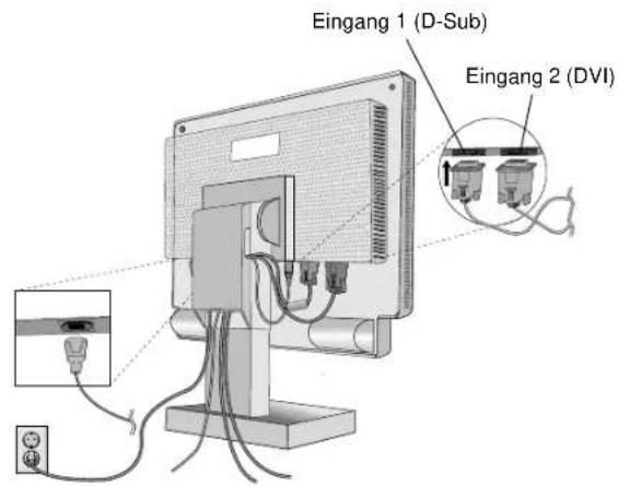
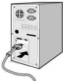
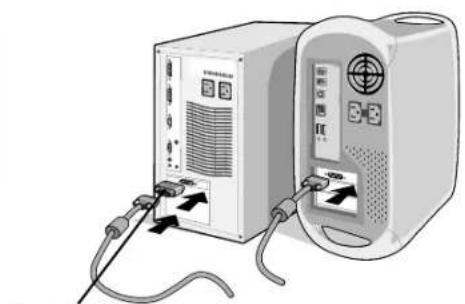
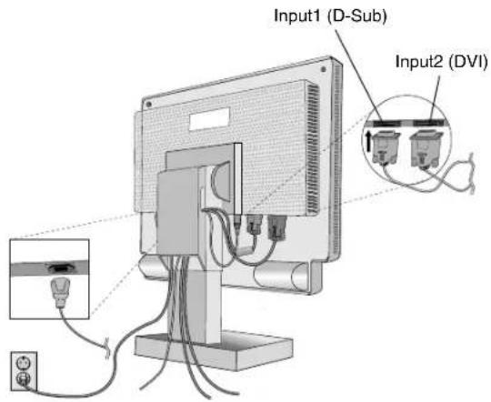
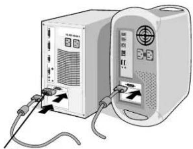
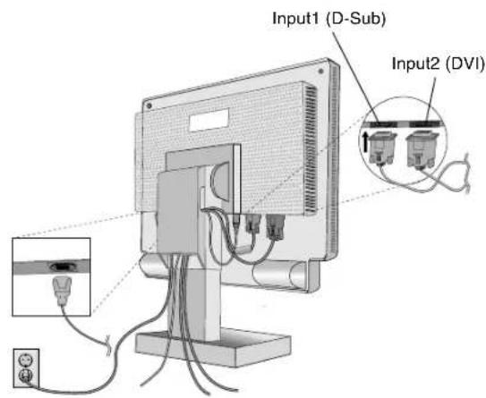
- Remove cable cover. Connect the 15-pin mini D-SUB of the video signal cable and DVI signal cable (not included) to the appropriate connector on the back of the monitor (Figure D.1).
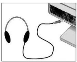
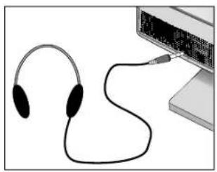
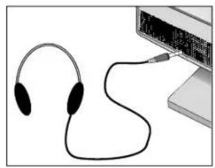
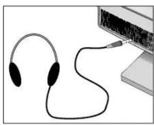
- Headphones may be connected to the "Headphones" output on the front of the monitor's bezel marked "○" (Figure E.1). While the headphones are connected, the sound from the speakers will be disabled. Headphones can be purchased from your local electronics store.
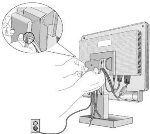
- Connect one end of the power cord to the monitor and the other end to the power outlet.
Collect cables and keep them at backside of the stand (Figure D.2). And cover the cables by the optional Cable management Cover (Figure D.3).
Please check Tilt, Rise and Lower monitor screen when you manage cables.
NOTE: Please refer to Caution section of this manual for proper selection of AC power cord.
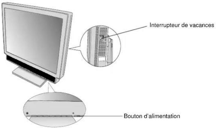
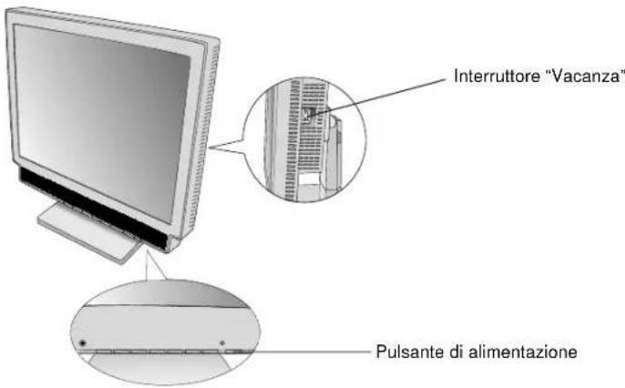
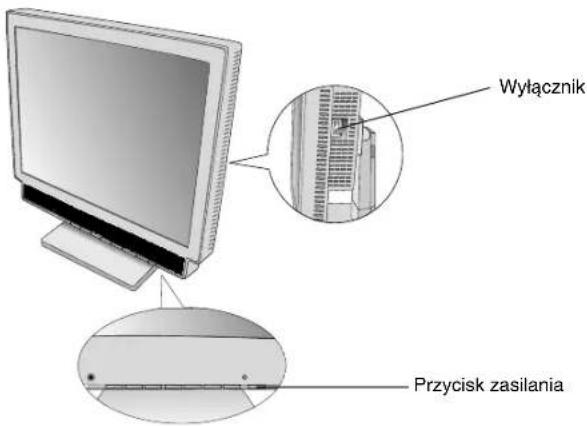
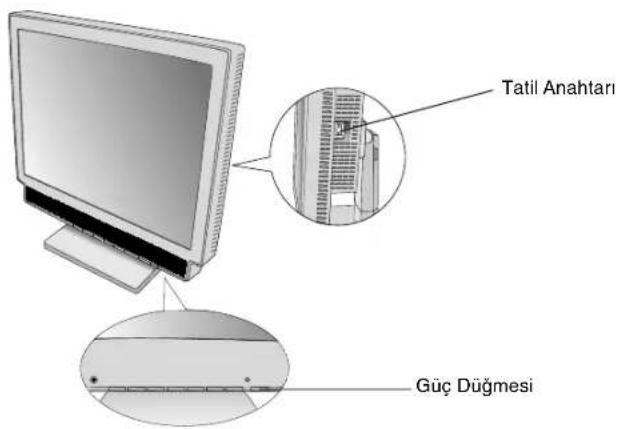
- The Vacation Switch on the right side of the monitor must be turned on (Figure F.1). Turn on the monitor with the Power Button and the computer.
NOTE: The Vacation Switch is a true on/off switch. If this switch is on the OFF position, the monitor cannot be turned on using the front button. DO NOT switch on/off repeatedly. - Analog input only: No-touch auto adjust automatically adjusts the monitor to optimal settings upon initial setup for most timings. For further adjustments, use the following OSM controls:
• Auto Adjust Contrast
- Auto Adjust
Refer to the Controls section of this User's Manual for a full description of these OSM controls.
NOTE: If you have any problems, please refer to the Troubleshooting section of this User's Manual.
natural_image
Diagram showing cable connection between a device panel and a separate panel with connectors (no text or symbols)Figure A.1

natural_image
Two computer monitors connected by cable, one with ports and connectors (no visible text or symbols)Figure B.1 Figure C.1

natural_image
Illustration of a computer tower with ports and cables (no visible text or symbols)Figure B.2

natural_image
Two electronic devices connected by cables, one with a labeled power supply unit and cable connectors (no visible text or symbols)Macintosh Cable Adapter (not included)
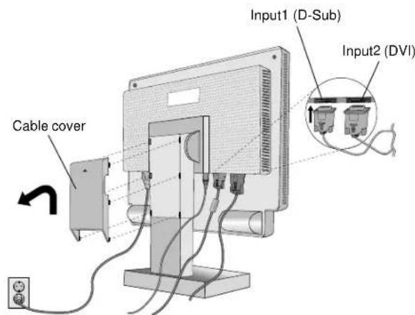
Figure D.1

natural_image
Illustration of a hand inserting cable into a computer monitor (no text or symbols visible)Figure D.2

Figure D.3

natural_image
Illustration of a pair of headphones connected to a computer monitor (no text or symbols visible)Figure E.1
English-3

Figure F.1
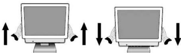
Raise and Lower Monitor Screen
The monitor may be raised or lowered.
To raise or lower screen, place hands on each side of the monitor and lift or lower to the desired height (Figure RL.1).
natural_image
Two computer monitors with upward and downward arrows indicating orientation (no text or symbols)Figure RL.1
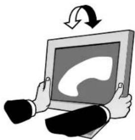
Tilt
Grasp both sides of the monitor screen with your hands and adjust the tilt as desired (Figure TS.1).
natural_image
Illustration of a person holding a tablet with a speech bubble icon, no text or symbols presentFigure TS.1
Remove Monitor Stand for Mounting
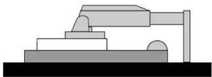
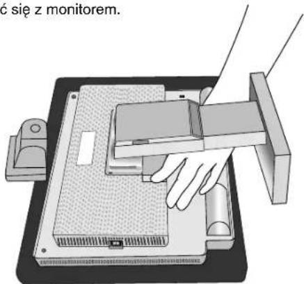
To prepare the monitor for alternate mounting purposes:
- Disconnect all cables.
- Place hands on each side of the monitor and lift up to the highest position.
- Place monitor face down on a non-abrasive surface. (Figure S.1)
natural_image
Pure mechanical diagram showing a lever and base structure without any text, numbers, or symbolsFigure S.1
English-4
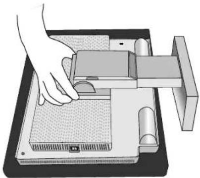
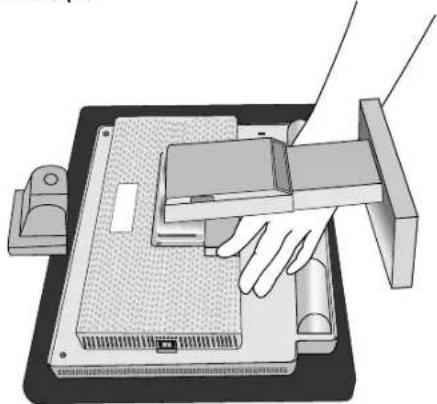
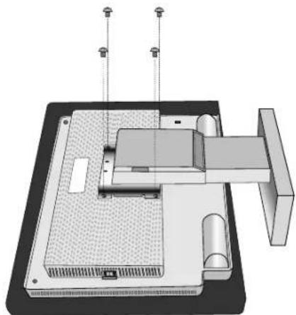
- Remove the hinge cover. (Figure R.1 and Figure R.2)
- Remove the 4 screws connecting the monitor to the stand and lift off the stand assembly (Figure R.3) the monitor is now ready for mounting in an alternate manner.
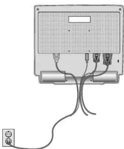
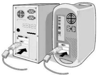
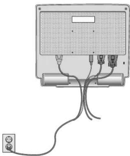
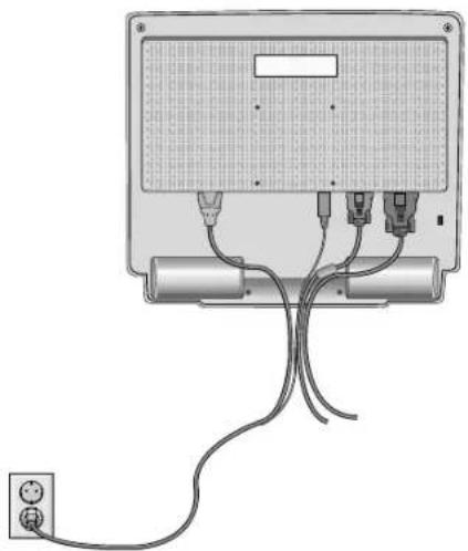
- Connect the AC cord, signal cable and audio cable to the back of the monitor (Figure R.4).
- Reverse this process to reattach stand.
NOTE: Use only VESA-compatible alternative mounting method.
Handle with care when removing monitor stand.
natural_image
Illustration of a hand operating a mechanical device with a tray and base (no text or symbols visible)
natural_image
Illustration of a hand operating a computer monitor with a handle, showing internal components and no text or symbols.Figure R.1 Figure R.2

natural_image
3D technical diagram of a mechanical assembly with mounting holes and internal components (no text or symbols)Figure R.3
natural_image
Diagram of a device with cables and connectors, no text or symbols presentFigure R.4
English-5
NOTE: This LCD monitor is designed for use with a flexible arm. Please use the attached screws (4pcs) when mounting. To meet the safety requirements the monitor must be mounted to an arm which guarantees the necessary stability under consideration of the weight of the monitor. The LCD monitor shall only be used with an approved arm (e.g. GS mark).
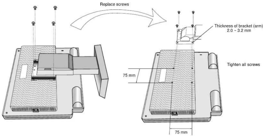
4 SCREWS
(MAX depth: 8.6 mm)
If use other screw,
check depth of hole.
natural_image
Illustration of a computer monitor with two buttons and a blank screen (no text or symbols)Weight of LCD assembly: 3.5kg (MAX)
Controls
OSM (On-Screen-Manager) Controls
The OSM controls on the front of the monitor function as follows: To access OSM press any of the control buttons (<, >, -, +, EXIT). To change signal input, press the SELECT button.
NOTE: OSM must be closed in order to change signal input.
Control Menu
EXIT Exits the OSM controls.
Exits to the OSM main menu.
</> Moves the highlighted area left/right to select control menus.
Moves the highlighted area up/down to select one of the controls.
- / + Moves the bar left/right to increase or decrease the adjustment.
SELECT Active Auto Adjust function. Enter the OSM controls. Enter the OSM sub menu.
RESET/MUTE Resets the highlighted control menu to the factory setting.
When no OSM menu is shown, the speaker sound will be muted.
NOTE: When RESET is pressed in the main and sub-menu, a warning window will appear allowing you to cancel the RESET function by pressing the EXIT button.
English-6

Sound

VOLUME
Control the sound volume of speakers and headphones. Tomute the speaker sound, press the MUTE key.

Brightness/Contrast Controls

BRIGHTNESS
Adjusts the overall image and background screen brightness.

CONTRAST
Adjusts the image brightness in relation to the background.

AUTO ADJUST (Analog input only)
Adjusts the image displayed for non-standard video inputs.
AUTO
Auto Adjust (Analog input only)
Automatically adjusts the Image Position, the H. Size and Fine setting.

Position Controls (Analog input only)

LEFT/RIGHT
Controls Horizontal Image Position within the display area of the LCD.

DOWN/UP
Controls Vertical Image Position within the display area of the LCD.

H. SIZE
Adjusts the horizontal size by increasing or decreasing this setting.
Should the "AUTO Adjust function" do not give you a satisfactory picture setting, a further tuning can be performed using the "H.Size" function (dot clock). For this a Moiré test pattern could be used. This function may alter the width of the picture. Use Left/Right Menu to center the image on the screen. If the H.Size is wrongly calibrated, the result would look like on the left drawing. The image should be homogeneous.
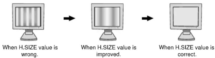
flowchart
graph LR
    A["When H.SIZE value is wrong."] --> B["When H.SIZE value is improved."]
    B --> C["When H.SIZE value is correct."]

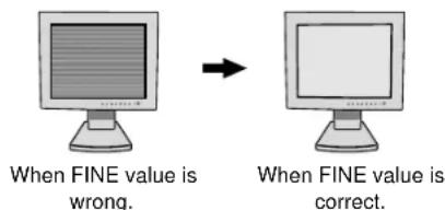
FINE
Improves focus, clarity and image stability by increasing or decreasing this setting.
Should the "Auto Adjust function" and the "H.Size" function do not give you a satisfactory picture setting, a fine tuning can be performed using the "Fine" function. It improves focus, clarity and image stability by increasing or decreasing this setting.
For this a Moiré test pattern could be used. If the Fine value is wrongly calibrated, the result would look like on the left drawing. The image should be homogeneous.
English-7
RGB Colour Control Systems
Six colour presets select the desired colour setting (sRGB and NATIVE colour presets are standard and cannot be changed).
R, G, B
Increases or decreases Red, Green or Blue colour depending upon which is selected. The change in colour will appear on screen and the direction (increase or decrease) will be shown by the bars.
sRGB
sRGB mode dramatically improves the colour fidelity in the desktop environment by a single standard RGB colour space. With this colour supported environment, the operator could easily and confidently communicate colours without further colour management overhead in the most common situations.
NATIVE
Original colour presented by the LCD panel that is unadjustable.

Tools

LANGUAGE
OSM control menus are available in seven languages.

OSM POSITION
You can choose where you would like the OSM control image to appear on your screen. Selecting OSM Location allows you to manually adjust the position of the OSM control menu left, right, down or up.

OSM TURN OFF
The OSM control menu will stay on as long as it is use. In the OSM Turn Off submenu, you can select how long the monitor waits after the last touch of a button to shut off the OSM control menu. The preset choices are 10, 20, 30, 45, 60 and 120 seconds.

OSM LOCK OUT
This control completely locks out access to all OSM control functions without Mute, Sound volume, Brightness and Contrast. When attempting to activate OSM controls while in the Lock Out mode, a screen will appear indicating the OSM controls are locked out. To activate the OSM Lock Out function, press SELECT, then “+” key and hold down simultaneously. To de-activate the OSM Lock Out, press SELECT, then “+” key and hold down simultaneously.

RESOLUTION NOTIFIER
This optimal resolution is 1024 x 768. If ON is selected, a message will appear on the screen after 30 seconds, notifying you that the resolution is not at 1024 x 768.

HOT KEY
You can adjust the sound volume and brightness directly. When this function is set to ON, you can adjust the sound volume with + or -, brightness with < or > key, while the OSM menu is off. The standard OSM menu can be accessed with the EXIT button.

OFF TIMER
Monitor will automatically power-down when the end user has selected a pre-determined amount of time.

FACTORY PRESET
Selecting Factory Preset allows you to reset all OSM control settings back to the factory settings. The RESET button will need to be held down for several seconds to take effect. Individual settings can be reset by highlighting the control to be reset and pressing the RESET button.
Information

DISPLAY MODE
Indicates the current display resolution and frequency setting of the monitor.

MONITOR INFO.
Indicates the model and serial numbers of your monitor.
OSM Warning
OSM Warning menus disappear with Exit button.
NO SIGNAL: This function gives a warning when there is no signal present. After power is turned on or when there is a change of input signal or video is inactive, the No Signal window will appear.
RESOLUTION NOTIFIER: This function gives a warning of use with optimized resolution. After power is turned on or when there is a change of input signal or the video signal doesn't have proper resolution, the Resolution Notifier window will open. This function can be disabled in the TOOL menu.
OUT OF RANGE: This function gives a recommendation of the optimized resolution and refresh rate. After the power is turned on or there is a change of input signal or the video signal doesn't have proper timing, the Out Of Range menu will appear.
Recommended use
Safety Precautions and Maintenance

FOR OPTIMUM PERFORMANCE, PLEASE NOTE THE FOLLOWING WHEN SETTING UP AND USING THE MULTISYNC LCD COLOUR MONITOR:

- DO NOT OPEN THE MONITOR. There are no user serviceable parts inside and opening or removing covers may expose you to dangerous shock hazards or other risks. Refer all servicing to qualified service personnel.
- Do not spill any liquids into the cabinet or use your monitor near water.
- Do not insert objects of any kind into the cabinet slots, as they may touch dangerous voltage points, which can be harmful or fatal or may cause electric shock, fire or equipment failure.
- Do not place any heavy objects on the power cord. Damage to the cord may cause shock or fire.
- Do not place this product on a sloping or unstable cart, stand or table, as the monitor may fall, causing serious damage to the monitor.
- Do not place any objects onto the monitor and do not use the monitor outdoors.
- The inside of the fluorescent tube located within the LCD monitor contains mercury. Please follow the bylaws or rules of your municipality to dispose of the tube properly.
Immediately unplug your monitor from the wall outlet and refer servicing to qualified service personnel under the following conditions:
- When the power supply cord or plug is damaged.
- If liquid has been spilled, or objects have fallen into the monitor.
- If the monitor has been exposed to rain or water.
- If the monitor has been dropped or the cabinet damaged.
- If the monitor does not operate normally by following operating instructions.
- Do not bend power cord.
- Do not use monitor in high tempered, humid, dusty, or oily areas.
- Do not cover vent on monitor.
- If monitor is broken, do not come in contact with the liquid crystal.
- If glass is broken. Handle with care.

CAUTION
- Allow adequate ventilation around the monitor so that heat can properly dissipate. Do not block ventilated openings or place the monitor near a radiator or other heat sources. Do not put anything on top of monitor.
- The power cable connector is the primary means of detaching the system from the power supply. The monitor should be installed close to a power outlet which is easily accessible.
- Handle with care when transporting. Save packaging for transporting.
- Image Persistence: Image persistence is when a residual or “ghost” image of a previous image remains visible on the screen. Unlike CRT monitors, LCD monitors’ image persistence is not permanent, but constant images being displayed for a long period of time should be avoided.
To alleviate image persistence, turn off the monitor for as long as the previous image was displayed. For example, if an image was on the monitor for one hour and a residual image remains, the monitor should be turned off for one hour to erase the image.
NOTE: As with all personal display devices, NEC-Mitsubishi Electronics Display-Europe recommends using a moving screen saver at regular intervals whenever the screen is idle or turning off the monitor when not in use.

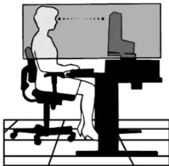
CORRECT PLACEMENT AND ADJUSTMENT OF THE MONITOR CAN REDUCE EYE, SHOULDER AND NECK FATIGUE. CHECK THE FOLLOWING WHEN YOU POSITION THE MONITOR:

- For optimum performance, allow 20 minutes for warm-up.
- Adjust the monitor height so that the top of the screen is at or slightly below eye level. Your eyes should look slightly downward when viewing the middle of the screen.
- Position your monitor no closer than 40 cm and no further away than 70 cm from your eyes. The optimal distance is 50 cm.
- Rest your eyes periodically by focusing on an object at least 6 m away. Blink often.
- Position the monitor at a 90^ angle to windows and other light sources to minimize glare and reflections. Adjust the monitor tilt so that ceiling lights do not reflect on your screen.
- If reflected light makes it hard for you to see your screen, use an antiglare filter.
- Clean the LCD monitor surface with a lint-free, non-abrasive cloth. Avoid using any cleaning solution or glass cleaner!
- Adjust the monitor's brightness and contrast controls to enhance readability.
- Use a document holder placed close to the screen.
- Position whatever you are looking at most of the time (the screen or reference material) directly in front of you to minimize turning your head while you are typing.
- Avoid displaying fixed patterns on the monitor for long periods of time to avoid image persistence (after-image effects).
- Get regular eye checkups.
natural_image
Silhouette of a person sitting at a desk using a computer, with no visible text or symbolsErgonomics
Torealize the maximum ergonomics benefits, we recommend the following:
- Use the preset Size and Position controls with standard signals.
- Use the preset Colour Setting.
- Use non-interlaced signals with a vertical refresh rate between 60-75 Hz.
- Do not use primary colour blue on a dark background, as it is difficult to see and may produce eye fatigue to insufficient contrast.

VAROVÁNÍ

CHRAŃTE ZAŘÍZENÍ PŘED DEŠTĚM A VLHKEM. ZABRÁNÍTE TAK NEBEZPEČÍ POŽÁRU NEBO ÚRAZU ELEKTRICKÝM PROUDEM. POLARIZOVANOU ZÁSTRČKU JEDNOTKY NEPOUŽÍVEJTE VE SPOJENÍ SE ZÁSUVKOU PRODLUŽOVACÍ ŠNŮRY NEBO JINÝMI ZÁSUVKAMI, POKUD KOLÍKY NELZE ZCELA ZASUNOUT.
UVNITŘ ZAŘÍZENÍ SE NACHÁZÍ VYSOKONAPĚTOVÉ KOMPONENTY, PROTO SKŘÍŇ NEOTEVÍREJTE. SERVIS SVĚŘTE KVALIFIKOVANÉ OSOBĚ.

UPOZORNĚNÍ

RIZIKO ÚRAZU ELEKTRICKÝM PROUDEM • NEOTVÍRAT
UPOZORNĚNÍ: Z DŮVODU SNÍŽENÍ RIZIK ÚRAZU ELEKTRICKÝM PROUDEM NEODNÍMEJTE KRYT (NEBO ZADNÍ ČÁST). UVNITŘ SE NENACHÁZEJÍ DÍLY, DO KTERÝCH UŽIVATEL MŮŽE ZASAHOVAT. SERVIS SVĚRTE KVALIFIKOVANÉ OSOBĚ.

MS Shibaura Bldg., 13-23,
Shibaura 4-chome,
Minato-Ku, Tokyo 108-0023, Japan
natural_image
Illustration of three electronic components: a coiled cable, connected cables with connectors, and a CD (no text or symbols)natural_image
Illustration of a flat-screen computer monitor with a stand (no text or symbols visible)natural_image
Diagram showing cable connection between a device panel and a TV outlet, with no visible text or symbols.Obrázek A.1

natural_image
Two computer monitors connected by cable, one with ports and cables, the other with a display (no visible text or symbols)natural_image
Illustration of a computer power supply unit with ports, cables, and a cable (no visible text or labels)Obrázek B.2

natural_image
Illustration of a computer setup with two connected devices, one showing ports and cables (no visible text or symbols)natural_image
Illustration of a hand inserting cables into a computer monitor, showing cable routing and a magnified view of the device (no text or symbols present)Obrázek D.2
Obrázek D.3

natural_image
Illustration of a pair of headphones connected to a computer monitor (no text or symbols visible)Obrázek E.1
Česky-3

natural_image
Two computer monitors with upward and downward arrows indicating orientation (no text or symbols)Obrázek RL.1
Sklon monitoru
natural_image
Illustration of a person holding a computer monitor with a curved screen and arrow symbol (no text or symbols present)Obrázek TS.1
natural_image
Mechanical diagram showing a lever system with blocks and a curved arm (no text or symbols)Obrázek S.1
Česky-4
natural_image
Illustration of a hand using a mechanical device to press or install a component (no text or symbols visible)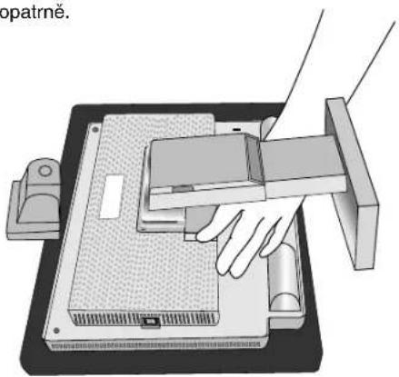
natural_image
3D technical diagram of a mechanical assembly with mounting base and housing (no visible text or symbols)Obrázek R.3

natural_image
Diagram of an electronic device with cables and connectors, no text or symbols presentObrázek R.4
Česky-5
natural_image
Diagram of a computer monitor with two buttons and a blank screen, no text or symbols presentnatural_image
Silhouette of a person sitting at a desk with a computer, viewed from behind (no text or symbols)Ergonomika
MS Shibaura Bldg., 13-23,
Shibaura 4-chome,
Minato-Ku, Tokyo 108-0023, JAPAN
natural_image
Two types of connected cables, one straight and one with connectors (no text or symbols visible)Audiokabel

Signalkabel
CD-ROM
natural_image
Illustration of a flat-screen computer monitor with a stand (no text or symbols visible)natural_image
Diagram showing cable connection between a device panel and a TV outlet, with no visible text or symbols.Abbildung A.1

natural_image
Two computer monitors connected by cable, one with ports and cables, the other showing a device inside (no visible text or symbols)natural_image
Illustration of a computer tower with ports and cables (no visible text or symbols)Abbildung B.2

natural_image
Illustration of two electronic devices connected by cables, one with a label and cable connectors (no readable text or symbols)natural_image
Illustration of a hand inserting cables into a computer monitor, showing cable routing and wiring (no text or symbols)Abbildung D.2
natural_image
Illustration of a pair of headphones connected to a computer monitor (no text or symbols visible)natural_image
Two identical computer monitors with upward and downward arrows indicating orientation (no text or symbols)Abbildung RL.1
Neigen
natural_image
Illustration of a person holding a tablet with a speech bubble and a curved arrow above it (no text or symbols)Abbildung TS.1
natural_image
Pure mechanical diagram showing a lever and base structure without any text, numbers, or symbolsAbbildung S.1
Deutsch-4
natural_image
Illustration of a hand using a mechanical device to press or install a component (no text or symbols visible)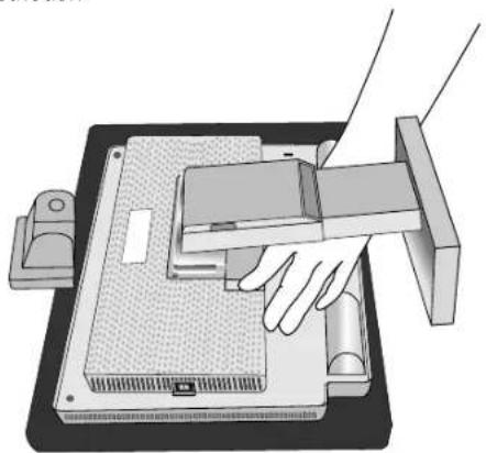
natural_image
Illustration of a hand pressing down on a computer monitor case (no text or symbols visible)natural_image
3D technical diagram of a mechanical assembly with mounting base and support structure (no text or symbols)Abbildung R.3

natural_image
Diagram of an electronic device with cables and connectors, no text or symbols presentnatural_image
Illustration of a computer monitor with two side buttons and a blank screen, no text or symbols present.natural_image
Silhouette of a person sitting at a desk with a computer, no text or symbols presentErgonomie
MS Shibaura Bldg., 13-23,
Shibaura 4-chome,
Minato-Ku, Tokyo 108-0023, JAPAN
natural_image
Illustration of a flat-screen computer monitor with a stand (no text or symbols visible)natural_image
Diagram showing cable connection between a computer monitor and a server unit, with no visible text or symbols.Σχήμα Α.1
natural_image
Two computer units with attached cables and ports, no visible text or symbolsΣχήμα Β.1 Σχήμα Γ.1
natural_image
Front view of a computer tower with attached cable and ports (no visible text or symbols)Σχήμα Β.2
natural_image
Illustration of a computer setup with two connected devices, one showing ports and cables (no visible text or labels)natural_image
Illustration of hands connecting cables to a computer monitor (no text or symbols visible)natural_image
Illustration of a pair of headphones connected to a computer monitor (no text or symbols visible)Σχήμα Ε.1
natural_image
Two identical computer monitors with upward and downward arrows indicating orientation (no text or symbols)Σχήμα ΡΛ.1
Ρύθμιση της κλίσης
natural_image
Illustration of hands holding a tablet with a speech bubble icon and curved arrows indicating rotation (no text or symbols)natural_image
Pure mechanical diagram showing a lever and base assembly without any text, numbers, or symbolsΣχήμα Σ.1
natural_image
Illustration of a hand using a mechanical device to press or install a tray (no text or symbols visible)Σχήμα P.1
Σχήμα P.2

natural_image
3D technical diagram of a mechanical assembly with mounting holes and internal components (no text or symbols)Σχήμα Ρ.3

natural_image
Diagram of a device with cables and connectors, no text or symbols presentH. SIZE (OPIZONTIO MEGEOΣ)
natural_image
Silhouette of a person sitting at a desk using a computer, viewed from behind (no text or symbols present)Εργονομία
Directiva 89/336/CEE:
- EN 55022
- EN 61000-3-2
- EN 61000-3-3
- EN 55024
y lleva la marca

NEC-Mitsubishi Electric Visual Systems, Corp.
MS Shibaura Bldg., 13-23, Shibaura 4-chome,
Minato-Ku, Tokyo 108-0023, JAPÓN
natural_image
Two types of connected cables, one straight and one with connectors (no text or symbols visible)Cable de audio
natural_image
Illustration of a flat-screen computer monitor with a stand (no text or symbols visible)natural_image
Diagram showing cable connection between a computer monitor and a server unit, with no visible text or symbols.Figura A.1

natural_image
Two computer units connected by cables, one with ports and arrows indicating data transfer (no visible text or symbols)Figura B.1 Figura C.1
natural_image
Illustration of a computer power supply unit with attached cable and ports (no text or symbols visible)Figura B.2
natural_image
Illustration of two electronic devices connected by cables, one with a labeled power supply unit (no text or symbols on the device body)natural_image
Illustration of a hand inserting cables into a computer monitor (no text or symbols visible)Figura D.2
Figura D.3
natural_image
Illustration of a pair of headphones connected to a computer monitor (no text or symbols visible)natural_image
Two identical computer monitors with upward and downward arrows indicating orientation (no text or symbols)Figura RL.1
Inclinación
natural_image
Illustration of a person holding a tablet with a speech bubble icon, no text or symbols presentFigura TS.1
natural_image
Pure mechanical diagram showing a lever and base structure without any text, numbers, or symbolsFigura S.1
Español-4
natural_image
Illustration of a hand operating a mechanical device with rollers and a tray (no text or symbols visible)
natural_image
Illustration of a hand operating a computer monitor with a handle, showing no text or symbols.Figura R.1 Figura R.2

natural_image
3D technical diagram of a mechanical assembly with mounting holes and internal components (no text or symbols)Figura R.3
natural_image
Diagram of a device with cables and connectors, no text or symbols presentflowchart
graph LR
    A["Computer monitor with vertical stripes"] --> B["Computer monitor with horizontal bars"]
    B --> C["Computer monitor with horizontal bars"]
APROXIMADO incorrecto APROXIMADO corregido APROXIMADO correcto

FINO
FINO incorrecto FINO correcto
Español-7

RGB Sistemas de control del color
natural_image
Silhouette of a person sitting at a desk with a computer, no text or symbols visibleErgonomía
MS Shibaura Bldg., 13-23,
Shibaura 4-chome,
Minato-Ku, Tokyo 108-0023, JAPON
natural_image
Two types of coiled electrical probes with connectors, shown from different angles (no text or symbols visible)Câble audio
CD-ROM

natural_image
Illustration of a flat-screen computer monitor with a stand (no text or symbols visible)natural_image
Diagram showing cable connection between a device panel and a TV outlet, with no visible text or symbols.Figure A.1
natural_image
Two computer monitors connected by cable, one with ports and cables, the other with a display (no visible text or symbols)Figure B.1 Figure C.1

natural_image
Illustration of a computer power supply unit with ports, cables, and connectors (no visible text or labels)Figure B.2
natural_image
Illustration of two connected devices with cables and ports, no visible text or symbolsnatural_image
Illustration of a hand inserting cables into a computer monitor, showing cable routing and wiring (no text or symbols)Figure D.2
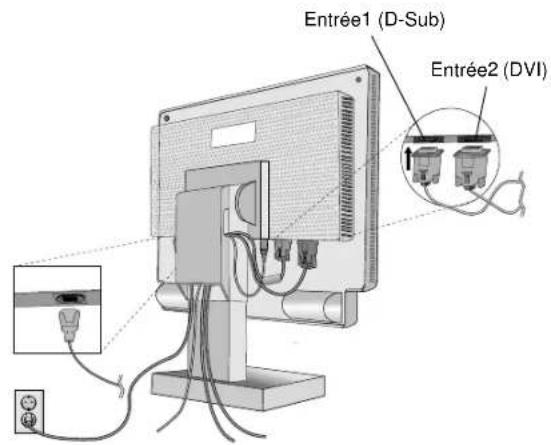
Figure D.3
natural_image
Illustration of a pair of headphones connected to a computer monitor (no text or symbols visible)Figure E.1
Français-3
natural_image
Two identical computer monitors with upward and downward arrows indicating orientation (no text or symbols)Figure RL.1
Inclinaison
natural_image
Illustration of a person holding a tablet with a speech bubble icon, no text or symbols presentFigure TS.1
natural_image
Pure mechanical diagram showing a lever and base structure without any text, numbers, or symbolsFigure S.1
Français-4
natural_image
Illustration of a hand operating a mechanical device with rollers and a tray (no text or symbols visible)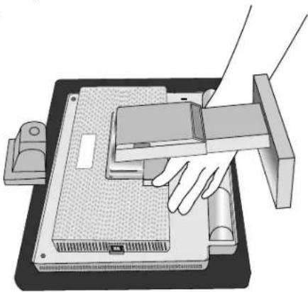
natural_image
Illustration of a hand operating a computer monitor with a handle, showing no text or symbols.Figure R.1 Figure R.2

natural_image
3D technical diagram of a mechanical assembly with mounting holes and internal components (no text or symbols)Figure R.3

natural_image
Diagram of a device with cable routing and a power outlet (no text or symbols)Figure R.4
Français-5
natural_image
Diagram of a computer monitor with two side monitors and a blank screen, no text or symbols presentnatural_image
Silhouette of a person sitting at a desk with a computer, no text or symbols visibleErgonomie
MS Shibaura Bldg., 13-23,
Shibaura 4-chome,
Minato-Ku, Tokyo 108-0023, Japan
natural_image
Illustration of three electronic components: a coiled cable, connected cables with connectors, and a CD (no text or symbols)natural_image
Illustration of a flat-screen computer monitor with a stand (no text or symbols visible)natural_image
Diagram showing cable connection between a computer monitor and a server unit, with no visible text or symbols.Figura A.1
natural_image
Two computer units connected by cables, one with ports and arrows indicating data transfer (no visible text or symbols)Figura B.1 Figura C.1

natural_image
Illustration of a computer power supply unit with attached cable and ports (no text or symbols visible)Figura B.2

natural_image
Illustration of two electronic devices connected by cables, one with a labeled power supply unit (no text or symbols on the device itself)Figura D.1
natural_image
Illustration of a hand inserting cables into a computer monitor (no text or symbols visible)Figura D.2

Figura D.3

natural_image
Illustration of a pair of headphones connected to a computer monitor (no text or symbols visible)Figura E.1
Italiano-3
natural_image
Two computer monitors with upward and downward arrows indicating orientation (no text or symbols)Figura RL.1
Inclinazione
natural_image
Illustration of a person holding a tablet with a speech bubble and circular arrow (no text or symbols)Figura TS.1
natural_image
Pure mechanical diagram showing a lever and base structure without any text, numbers, or symbolsFigura S.1
Italiano-4
natural_image
Illustration of a hand using a mechanical device to press or install a component (no text or symbols visible)
natural_image
Illustration of a hand operating a computer monitor with a handle, showing no text or symbols.Figura R.1 Figura R.2

natural_image
3D technical diagram of a mechanical assembly with mounting holes and internal components (no text or symbols)Figura R.3

natural_image
Diagram of a device with cable and power outlet, no text or symbols presentFigura R.4
Italiano-5
Controlli OSM (On-Screen Manager)
natural_image
Silhouette of a person sitting at a desk with a computer, no text or symbols presentErgonomia
MultiSync LCD1560VM (L152EM) in
overeenstemming is met
MS Shibaura Bldg., 13-23,
Shibaura 4-chome,
Minato-Ku, Tokyo 108-0023, Japan
natural_image
Two types of electrical probes with coiled wires, no visible text or symbolsnatural_image
Diagram showing cable connection between a device panel and a separate panel with connectors (no text or symbols)Illustratie A.1

natural_image
Two computer monitors connected by cable, one with ports and cables, the other with a display (no visible text or symbols)natural_image
Illustration of a computer tower with ports and cables (no visible text or symbols)Illustratie B.2

natural_image
Two electronic devices connected by cables, one with a labeled power outlet and cable connectors (no visible text or symbols)natural_image
Illustration of a hand inserting cables into a computer monitor, showing cable routing and wiring (no text or symbols)Illustratie D.2
Illustratie D.3

natural_image
Illustration of a pair of headphones connected to a computer monitor (no text or symbols visible)natural_image
Two computer monitors with upward and downward arrows indicating orientation (no text or symbols)Illustratie RL.1
Kantelen
natural_image
Illustration of a person holding a tablet with a speech bubble icon, no text or symbols presentIllustratie TS.1
natural_image
Mechanical assembly diagram showing a lever and base components (no text or symbols)Illustratie S.1
Nederlands-4
natural_image
Illustration of a hand using a mechanical device to press or install a component (no text or symbols visible)
natural_image
Illustration of a hand operating a mechanical device with a tray and base (no text or symbols visible)natural_image
3D technical diagram of a mechanical assembly with mounting base and vertical supports (no text or symbols)Illustratie R.3
natural_image
Diagram of a device with three connected cables and a power outlet, no text or symbols presentnatural_image
Illustration of a computer monitor with two side buttons and a screen displaying a blank rectangular area (no text or symbols)DOWN/UP (OMHOOG/OMLAAG)
natural_image
Two computer monitors with blank screens, one showing a right-pointing arrow (no text or symbols)DISPLAY MODE (WEERGAVEMODUS)
natural_image
Silhouette of a person sitting at a desk with a computer, no text or symbols visibleErgonomie
MS Shibaura Bldg., 13-23,
Shibaura 4-chome,
Minato-Ku, Tokyo 108-0023, Japan

natural_image
Two types of electrical connectors with coiled wires, no text or symbols visibleKabel Audio
Dysk CD-ROM
natural_image
Illustration of a flat-screen computer monitor with a stand (no text or symbols visible)natural_image
Diagram showing cable connection between a computer panel and a server unit, with no visible text or symbols.Rysunek A.1

natural_image
Two electronic devices with connected cables, one front and one side, showing ports and wiring (no visible text or symbols)natural_image
Illustration of a computer tower with power cord and cable (no text or symbols)Rysunek B.2
natural_image
Illustration of two connected computer devices with cables and ports (no visible text or symbols)natural_image
Illustration of a hand inserting cable into a computer monitor, showing wiring and components (no text or symbols)Rysunek D.2
Rysunek D.3
natural_image
Illustration of a pair of headphones connected to a computer monitor (no text or symbols visible)Rysunek E.1
natural_image
Two identical computer monitors with upward and downward arrows indicating orientation (no text or symbols)Rysunek RL.1
Pochylenie ekranu
natural_image
Illustration of a person holding a tablet with a speech bubble icon, no text or symbols presentnatural_image
Pure mechanical diagram showing a lever and base structure without any text, numbers, or symbolsRysunek S.1
natural_image
Illustration of a hand operating a mechanical device with a roller and housing (no text or symbols visible)Rysunek R.1
natural_image
3D technical diagram of a mechanical assembly with mounting base and internal components (no text or symbols)Rysunek R.3
Polski-6

natural_image
Diagram of an electronic device with cables and a power outlet, no text or symbols presentRysunek R.4
natural_image
Illustration of a computer monitor with two buttons and a blank screen, no text or symbols presentMasa zestawu LCD: 3,5 kg (MAKS.)
Polski-7
Przyciski
Sterowanie OSM (On-Screen-Manager)
DOWN/UP (POZYCJA PIONOWA)
DISPLAY MODE (TRYB PRACY)
natural_image
Silhouette of a person sitting at a desk with a computer, no text or symbols visibleErgonomia
MS Shibaura Bldg., 13-23,
Shibaura 4-chome,
Minato-Ku, Tokyo 108-0023, Japan

BZ 02
natural_image
Two types of electrical connectors: a coiled wire and a connected terminal (no text or symbols visible)аудиосигнала
natural_image
Illustration of a flat-screen computer monitor (no text or symbols visible on the screen)natural_image
Diagram showing cable connection between a device panel and a terminal, with an arrow indicating direction of connection (no text or symbols present)Рисунок А.1
natural_image
Two computer units connected by cable, one with ports and arrows indicating data transfer (no visible text or symbols)natural_image
Front view of a computer control unit with ports, cables, and an attached connector (no visible text or symbols)Рисунок В.2
natural_image
Illustration of a computer tower connected to a server unit via cables (no text or symbols visible)natural_image
Illustration of hands connecting cables to a computer monitor (no text or symbols visible)Рисунок D.2
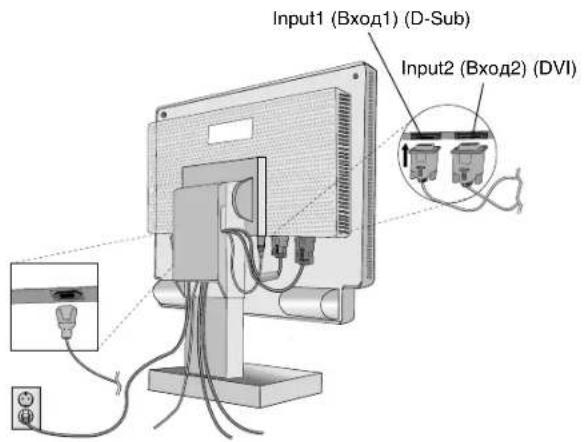
Рисунок D.3
natural_image
Illustration of a pair of headphones connected to a computer monitor (no text or symbols visible)Рисунок Е.1

natural_image
Two identical computer monitors with upward and downward arrows indicating orientation (no text or symbols)Рисунок RL.1
Наклон
natural_image
Illustration of a person holding a tablet with a curved arrow above it, no text or symbols presentРисунок TS.1
Русский-4
natural_image
Pure mechanical diagram showing a lever and base structure without any text, numbers, or symbolsРисунок S.1
natural_image
Illustration of a hand using a mechanical device to press or install a component, with no visible text or symbols.Рисунок R.1
natural_image
Illustration of a hand pressing down on a mechanical device component (no text or symbols visible)Рисунок R.2

natural_image
3D technical diagram of a mechanical assembly with no visible text or symbolsРисунок R.3
natural_image
Diagram of a mounted electronic device with cables and power outlet, no text or symbols presentРисунок R.4
natural_image
Illustration of a computer monitor with multiple lines pointing outward from the screen (no text or symbols)natural_image
Silhouette of a person sitting at a desk with a computer, no text or symbols presentЭргономика
MultiSync LCD1560VM (L152EM)
MS Shibaura Bldg., 13-23,
Shibaura 4-chome,
Minato-Ku, Tokyo 108-0023, JAPONYA
natural_image
Three types of electrical connectors and a circular component: coiled wire, connector, and disc (no text or symbols visible)Ses Kablosu
Video Sinyal Kablosu
CD ROM

natural_image
Illustration of a flat-screen computer monitor with a stand (no text or symbols visible)natural_image
Diagram showing cable connection between a device panel and a separate panel with connectors (no text or symbols)Şekil A.1

natural_image
Two computer monitors connected by cable, one with ports and cables, the other with a display (no visible text or symbols)Şekil B.1 Şekil C.1
natural_image
Illustration of a computer power supply unit with ports, cables, and connectors (no visible text or labels)Şekil B.2

natural_image
Two electronic devices connected by cables, one with a labeled power supply unit and cable connectors (no visible text or symbols)natural_image
Illustration of a hand inserting cables into a computer monitor, showing cable routing and wiring (no text or symbols)Şekil D.2
Şekil D.3
natural_image
Illustration of a pair of headphones connected to a computer monitor (no text or symbols visible)Şekil E.1
Türkçe-3
natural_image
Two computer monitors with upward and downward arrows indicating orientation (no text or symbols)Şekil RL.1
Eğim
natural_image
Illustration of a person holding a tablet with a speech bubble icon, no text or symbols presentŞekil TS.1
natural_image
Pure mechanical diagram showing a lever and base structure without any text, numbers, or symbolsŞekil S.1
Türkçe-4
natural_image
Illustration of a hand using a mechanical device to press or install a textured surface (no text or symbols visible)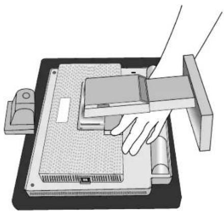
natural_image
Illustration of a hand operating a computer monitor with a handle, showing no text or symbols.Şekil R.1 Şekil R.2
natural_image
3D technical diagram of a mechanical assembly with mounting base and support structure (no text or symbols)Şekil R.3

natural_image
Diagram of a device with cable and power outlet, no text or symbols presentŞekil R.4
Türkçe-5
natural_image
Illustration of a computer monitor with two side buttons and a screen displaying a blank area (no text or symbols)natural_image
Silhouette of a person sitting at a desk with a computer, no text or symbols presentErgonomi
Printed on recycled paper


- For the Customer to use in U.S.A. or Canada
- Canadian Department of Communications Compliance Statement
- Declaration of Conformity
- TCO'99
- Why do we have environmentally labelled computers?
- What does labelling involve?
- Environmental Requirements
- Flame retardants
- Lead\*\*
- Cadmium\*\*
- Mercury\*\*
- CFCs (freons)
- Index
- CAUTION
- Caution:
- Declaration
- Declaration of the Manufacturer
- Contents
- Quick Start
- Raise and Lower Monitor Screen
- Tilt
- Remove Monitor Stand for Mounting
- Controls
- OSM (On-Screen-Manager) Controls
- English-6
- Sound
- VOLUME
- Brightness/Contrast Controls
- BRIGHTNESS
- CONTRAST
- AUTO ADJUST (Analog input only)
- Position Controls (Analog input only)
- LEFT/RIGHT
- DOWN/UP
- SIZE
- FINE
- RGB Colour Control Systems
- R, G, B
- sRGB
- NATIVE
- Tools
- LANGUAGE
- OSM POSITION
- OSM TURN OFF
- OSM LOCK OUT
- RESOLUTION NOTIFIER
- HOT KEY
- OFF TIMER
- FACTORY PRESET
- Information
- DISPLAY MODE
- MONITOR INFO.
- OSM Warning
- Recommended use
- Safety Precautions and Maintenance
- CORRECT PLACEMENT AND ADJUSTMENT OF THE MONITOR CAN REDUCE EYE, SHOULDER AND NECK FATIGUE. CHECK THE FOLLOWING WHEN YOU POSITION THE MONITOR:
- Ergonomics
- VAROVÁNÍ
- UPOZORNĚNÍ
- Sklon monitoru
- Ergonomika
- Neigen
- Ergonomie
- Ρύθμιση της κλίσης
- SIZE (OPIZONTIO MEGEOΣ)
- Εργονομία
- Inclinación
- FINO
- Español-7
- RGB Sistemas de control del color
- Ergonomía
- Inclinaison
- Inclinazione
- Controlli OSM (On-Screen Manager)
- Ergonomia
- Kantelen
- DOWN/UP (OMHOOG/OMLAAG)
- DISPLAY MODE (WEERGAVEMODUS)
- Pochylenie ekranu
- Przyciski
- Sterowanie OSM (On-Screen-Manager)
- DOWN/UP (POZYCJA PIONOWA)
- DISPLAY MODE (TRYB PRACY)
- Наклон
- Эргономика
- Eğim
- Ergonomi
Brand : NEC
Model : MultiSync LCD1560VM
Category : Monitor