
SF133 - Pool safety barrier GRE - Free user manual and instructions
Find the device manual for free SF133 GRE in PDF.
| Product type | Pool safety barrier |
| Brand | Gre |
| Model | SF133 |
| Panel dimensions (L x H) | 300 cm x 110 cm |
| Number of posts per panel | 4 |
| Maximum spacing between posts | 100 cm |
| Main material | Aluminum and polyester mesh |
| Panel weight (approx.) | Approximately 12 kg |
| Installation type | Ground fixing with anchors on hard surface (concrete slab) |
| Minimum clearance height | 1.10 m (compliant with NF P 90-306) |
| Opening system | Removable locking hooks |
| Recommended distance between barrier and water | 1 m minimum, ideally 1 m to 1.5 m |
| Mandatory safety radius (no support points) | 1.10 m on each side |
| Safety standard | NF P 90-306 |
| Maintenance | Regular cleaning, checking locks and components |
| Spare parts available | Hooks, anchors, covers, posts |
| Warranty | 2 years (conformity defects) |
Frequently Asked Questions - SF133 GRE
User questions about SF133 GRE
0 question about this device. Answer the ones you know or ask your own.
Ask a new question about this device
Download the instructions for your Pool safety barrier in PDF format for free! Find your manual SF133 - GRE and take your electronic device back in hand. On this page are published all the documents necessary for the use of your device. SF133 by GRE.
USER MANUAL SF133 GRE
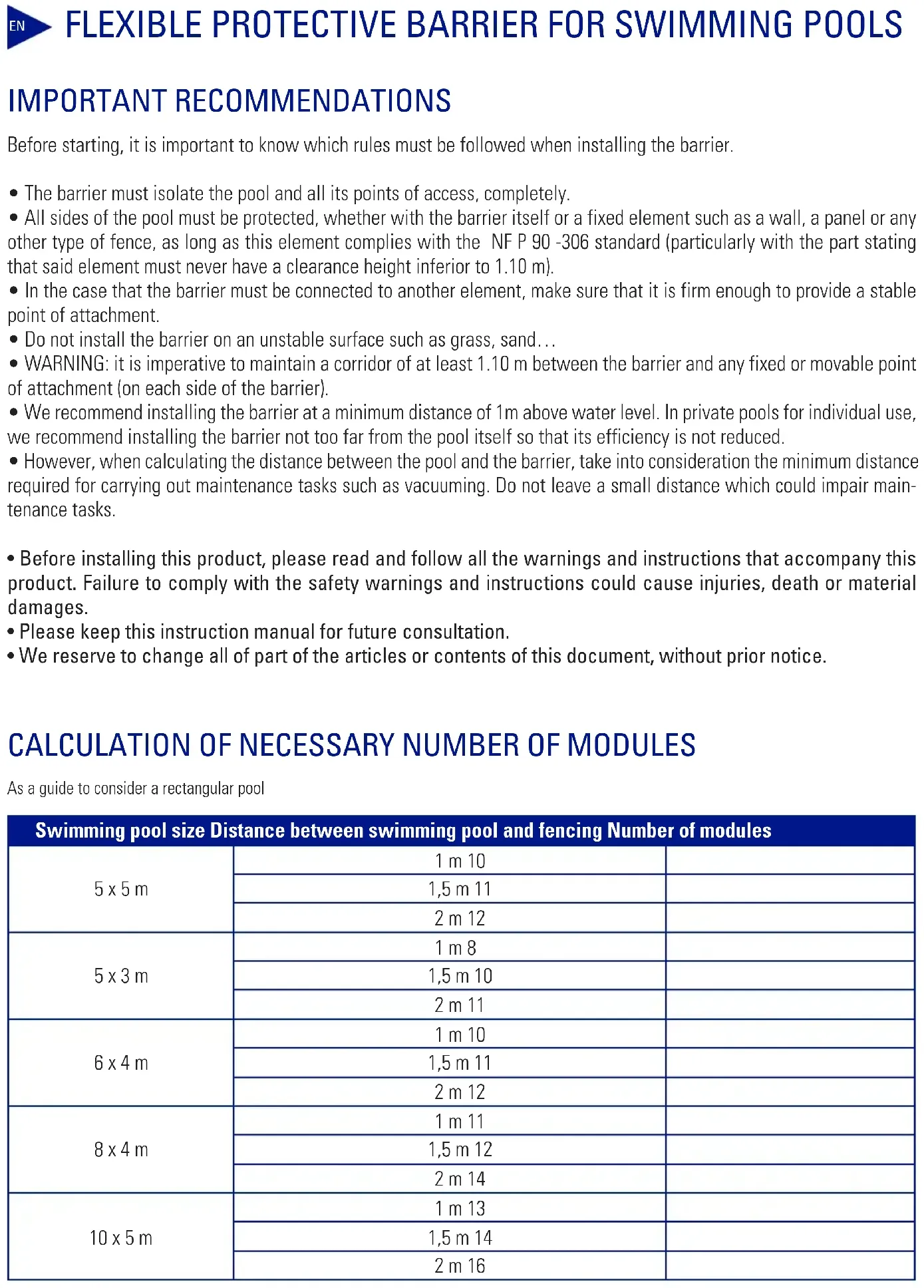
EN SAFETY FENCE FOR SWIMMING POOL
ES BARRERA DE PROTECCION PARA PISCINAS
FR BARRIERE DE PROTECTION POUR PISCINE
DE SCHUTZABSPERRUNG FÜR POOLS
BARRIERA DI PROTEZIONE PER PISCINE
NL VEILIGHEIDSHEKWERK VOOR ZWEMBADEN
BARREIRA DE PROTEÇÃO PARA PISCINAS
Instruction Manual - Manual de Instrucciones Manuel d'instructions - Bedienungsanleitung Manuale delle instruzioni - Handleiding met instructies Manual de instruções
We reserve to change all of part of the articles or contents of this document, without prior notice.
Before starting, it is important to know which rules must be followed when installing the barrier.
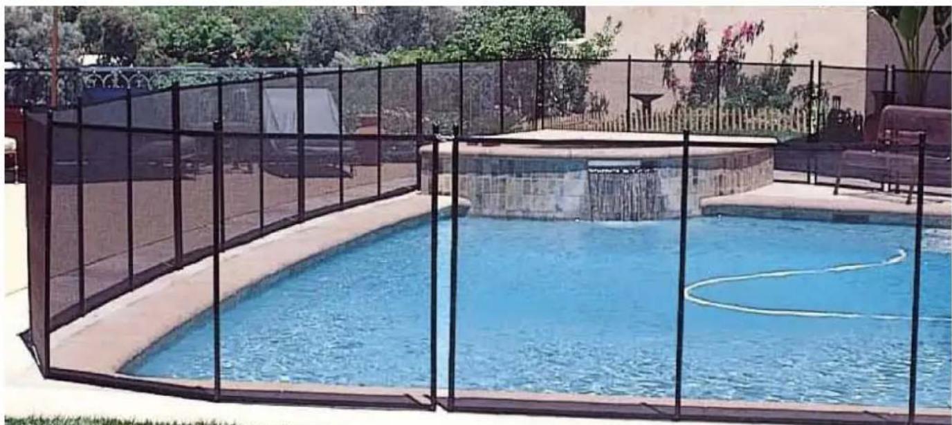
- The barrier must isolate the pool and all its points of access, completely.
- All sides of the pool must be protected, whether with the barrier itself or a fixed element such as a wall, a panel or any other type of fence, as long as this element complies with the NF P 90 -306 standard (particularly with the part stating that said element must never have a clearance height inferior to 1.10m ).
- In the case that the barrier must be connected to another element, make sure that it is firm enough to provide a stable point of attachment.
- Do not install the barrier on an unstable surface such as grass, sand...
- WARNING: it is imperative to maintain a corridor of at least 1.10m between the barrier and any fixed or movable point of attachment (on each side of the barrier).
- We recommend installing the barrier at a minimum distance of 1m above water level. In private pools for individual use, we recommend installing the barrier not too far from the pool itself so that its efficiency is not reduced.
- However, when calculating the distance between the pool and the barrier, take into consideration the minimum distance required for carrying out maintenance tasks such as vacuuming. Do not leave a small distance which could impair maintenance tasks.
- Before installing this product, please read and follow all the warnings and instructions that accompany this product. Failure to comply with the safety warnings and instructions could cause injuries, death or material damages.
- Please keep this instruction manual for future consultation.
We reserve to change all of part of the articles or contents of this document, without prior notice.
CALCULATION OF NECESSARY NUMBER OF MODULES
As a guide to consider a rectangular pool
| Swimming pool size Distance between swimming pool and fencing Number of modules | ||
| 5 x 5 m | 1 m 10 | |
| 1,5 m 11 | ||
| 2 m 12 | ||
| 5 x 3 m | 1 m 8 | |
| 1,5 m 10 | ||
| 2 m 11 | ||
| 6 x 4 m | 1 m 10 | |
| 1,5 m 11 | ||
| 2 m 12 | ||
| 8 x 4 m | 1 m 11 | |
| 1,5 m 12 | ||
| 2 m 14 | ||
| 10 x 5 m | 1 m 13 | |
| 1,5 m 14 | ||
| 2 m 16 | ||
CONTENT OF PACKAGE
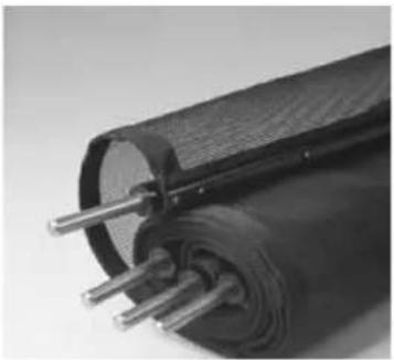
1 preinstalled 3 m panel, including a net and 4 poles, with adjustable length
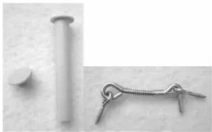
Content of 1 bag:
4 pegs
4 peg covers
1 hook
1 template for hole placement
REQUIRED TOOLS
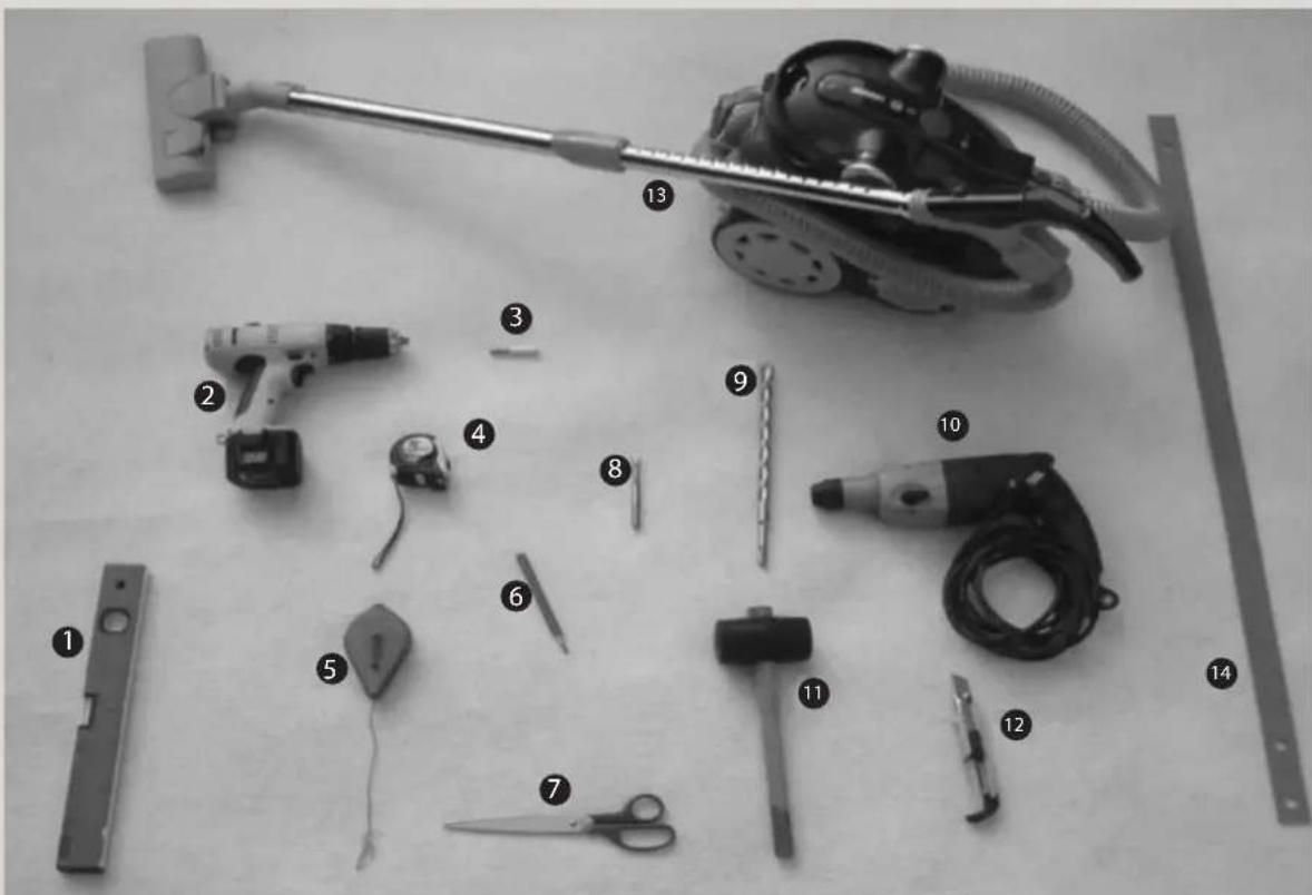
Spirit level
Screwdriver
Bit holder for screwdriver
4 Measuring tape or foldable ruler
Drawing pen
6 Pencil
7 Scissors
Concrete drill 10 (optional)
Concrete drill bit 10
10 Hammer drill for drill bits 16 0
Rubber mallet
Cutter
Vacuum cleaner
Template for detecting breakages
INSTALLATION OF BARRIER
PROLOGUE
WARNING: THE BARRIER CAN ONLY BE INSTALLED ON A SOLID, FIRM AND, IF POSSIBLE, THICK BASE. THE IDEAL SURFACE FOR THE INSTALLATION OF THE BARRIER IS A CONCRETE LAYER.
- Make sure you leave enough space surrounding the pool in order to be able to work without any problems.
- The surface must be clean and dry in order to be able distinguish clearly the marks made on the surface
- Do not begin to install the barrier if weather conditions are not optimal. You will have to use electrical devices, such as hammer drills. Out of precaution, do not use these devices in the rain or on damp surfaces. In all cases, electrical devices must be connected to a power socket equipped with a reverse current circuit breaker of 30mA .
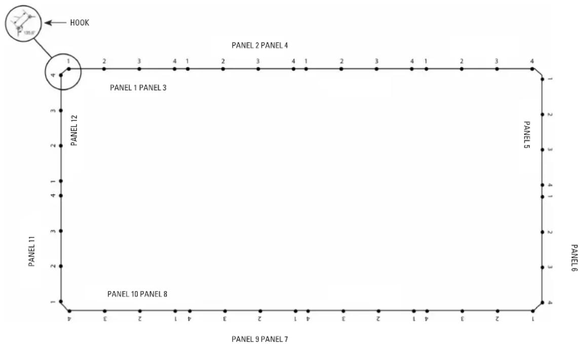
1. ESTABLISHING A STARTING POINT
Use a rope for the straight parts so that the layout is completely rectilinear.
2. TRACE THE 4 MARKS TO DESIGNATE THE 4 POLES OF THE FIRST PANEL
Using the two opposing holes of the template provided or a measuring tape, mark the 4 holes of the first panel, moving the template from the last hole marked.
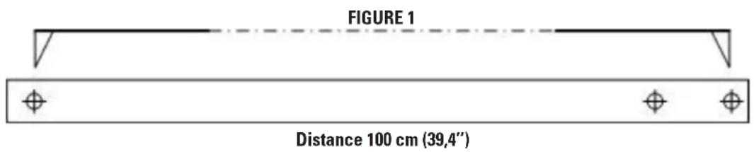
IMPORTANT: In the case that the barrier has to be installed on a bend, the distance must be adjusted around 5 mm, upwards or downwards, in order to achieve the desired net tension (see diagram in paragraph 3).
3. MAKING THE HOLES
The holes must be made with drill bit 16 . If the initial hole is made using the drill bit 10 then it may be easier to carry out the definitive drilling with 16 .
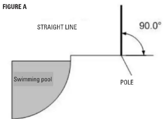
- With the help of a spirit level, make the holes that have been marked following these instructions: If the holes are in a straight line, they should all be at a 90^ angle from the deck.
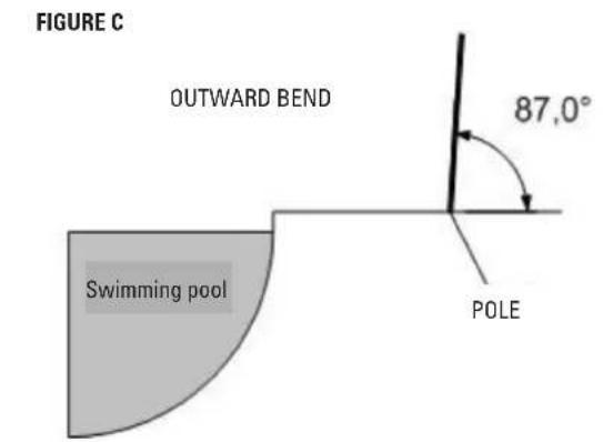
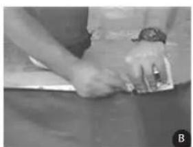
- If the holes are on an outward bend (see diagram at the end of the page), when marking the holes, reduce from 3 to 5mm the standard distance indicated by the drilling template. On an outward bend, the fabric covers more of the pole (See fig. B) than if it is a straight line. This is why we reduce the spacing between the poles by a few millimetres. At the time of making the holes, tilt the drill from 2^ to 4^ towards the outside of the pool with the aim of providing poles with a slightly outward incline. Said incline will guarantee that the net has the optimum tension on the superior part of the barrier. If the bend is not too pronounced, 2^ is probably enough; if, on the contrary, the bend is more noticeable, then 4^ (See fig. C).
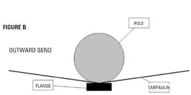
On an outward bend, the fabric covers more of the pole than if it is a straight line.
- If the holes are on an inward bend (see diagram at the end of the page), when marking the holes increase from 3 to 5 mm the standard distance indicated by the drilling template. On an inward bend, the fabric covers less of the pole (See fig. D) than if it is a straight line. This is why we increase the spacing between the poles by a few millimetres. At the time of making the holes, tilt the drill from 2^ to 4^ towards the inside of the pool with the aim of providing poles with a slightly inward incline. Said incline will guarantee that the net has the optimum tension on the superior part of the barrier. If the bend is not too pronounced, 2^ is probably enough; if, on the contrary, the bend is more noticeable, then 4^ (See fig. E).
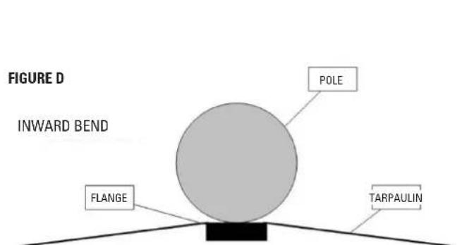
When the bend goes inwards, the fabric covers the pole slightly less than if it is a straight line, so there is a need to increase the space between the poles by a few millimetres.
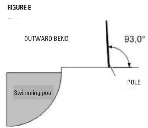
The inclination of the poles, depending on the bend, can help achieve the optimum tension on the superior part of the net.

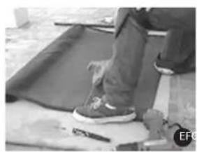
4. INSTALLATION OF PEGS AND PANEL
Once the 4 holes have been made, remove the interior and surrounding dirt and dust with a vacuum cleaner. Manually insert the pegs, and if required, finish putting them in with the help of a mallet. Then install the first panel. Fitting the poles into the pegs requires a bit of effort so it is more convenient to raise the pole with a slight incline towards the hole in order to slide the supporting end and then to straighten the pole to pin it down completely. If you are not able to fix the pole in place you might need to repeat the drilling.
Note: the fabric of the superior part of the panel could appear to lack tension. Tension will be achieved when all panels are in place and joined together.
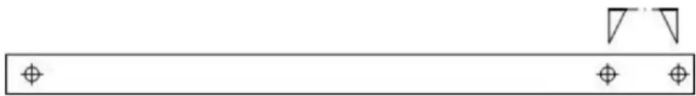
FIGURE 2
Distance 7,6 cm (3")
5. SUBSEQUENT PANELS
Continue on to the next panel with the layout template in order to determine the location of the first pole in this panel. Starting from the hole of the last pole of the panel that has just been installed, apply the template using the two closest holes this time (see figure 2). This space of 7.6cm represents the space between the last pole of the last panel and the first pole of the next panel.
6. REPEAT STEPS FROM PARAGRAPS 2 TO 5 UNTIL ALL HOLES HAVE BEEN DRILLED AND ALL PANELS HAVE BEEN PLACED.
Important: 90^g Angle
We do not recommend constructing the barrier with angles equal or inferior to 90^ .
Nevertheless, sometimes it cannot be done any other way.
It is not necessary to use this angle with a single corner pole because tension could make it bend. On the contrary, it is necessary to place in the angle the pole of the panel and the first pole of the next panel, joined by a connection hook. Follow the example of the following diagram.
Use 2 closely spaced holes in template
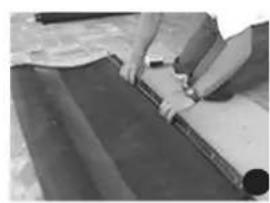
7. ADJUSTING THE LENGTH OF A PANEL
Sometimes it is necessary to modify the length of a panel. For this purpose, stick to the following procedure with a standard panel.
A) Determine the length of the panel that you wish to modify by measuring the distance between the centre of both holes on the floor.
B) Move that distance on the section of the panel you wish to modify from the centre of the pole that will be in place. Take into consideration the distance on the superior and inferior parts of the net.
WARNING: The distance between two poles must always be equal or inferior to 100cm
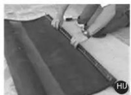
C) With the scissors, cut the fabric AIMING TO LEAVE 10 CM OF EXCESS LENGTH IN ORDER TO BE ABLE TO MAKE AN ADJUSTMENT IN CASE OF ERROR.
D) Release the flange of the unused pole (for example, the one connected to the excess fabric you have just cut). In order to release the flange, use an electric screwdriver and a standard bit holder (this corresponds to the flange screw).


E) With the help of the cord, trace a straight line between the two marks made in step b).
F) Fold the fabric on itself at 1.5cm from the line traced previously.
G) Place the fabric on the pole in such a manner that the flange screw holes are aligned with the line traced in step e). The line should fit perfectly with the flange screws. Place the flange and screw it on again completely. Make sure you place the pole in the right direction.
H) Try to replace the panel. If the section has not been modified, go back to stage a).
If there is a need to cut excess fabric in the panel, be careful to cut the right segment.
J) OPTIONAL: In order to avoid fraying of superior and inferior edges, a small welding device or lighter may be used to weld wires.
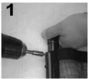
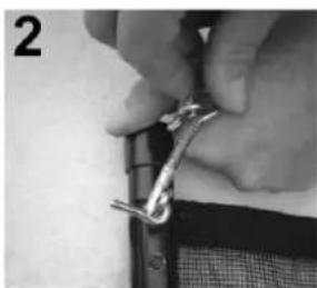
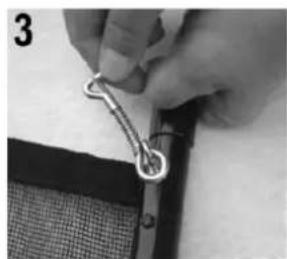
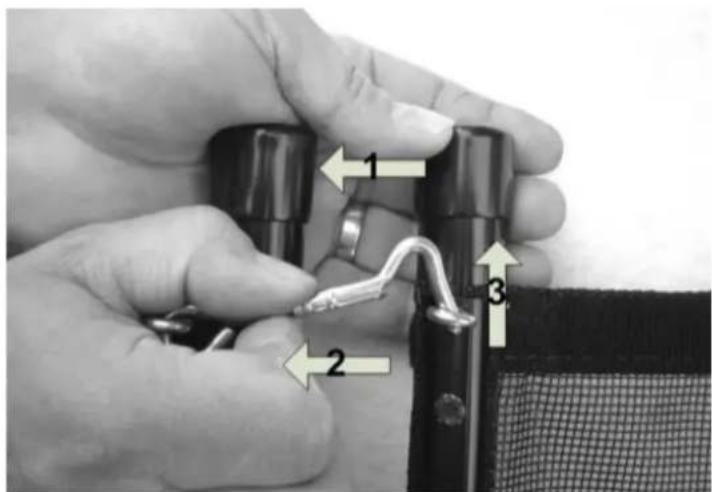
8. INSTALLING THE LOCK HOOKS
When all the holes are drilled and all the panels installed, they need to be connected to one another using the lock hooks included in the package. To install the hooks, follow these steps:
- Release the superior screw of the poles with the help of a screwdriver and a bit holder (See 1).
- With the hook, screw karabiners to the poles (see 2 and 3).
-
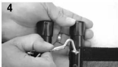
To close the hook, follow these steps (see 4).
-
Hold the two poles and put pressure on them to bring them closer together
- Release the safety latch (the movable piece on one end of the spring)
- Lower the hook and let go of it
USE AND MAINTENANCE
9. ACCESS TO THE POOL
It is possible to access the pool through each of the panel connections, by unblocking the safety hooks.
Follow these steps:
- Hold the two poles and put pressure on them to bring them closer together.
- Release the safety latch (the movable piece on one end of the spring).
- Lift up the hook to release the connection between the panels.
- Lift up the pole by turning it.
WARNING: the pole cannot be removed if you simply pull without turning it at the same time.
IT IS IMPERATIVE THAT ACCESS POINTS ARE CLOSED AT THE END OF THE SEASON OF SUPERVISED SWIMMING.
10. MAINTENANCE
Try to regularly monitor all barrier components. If any of the components should be damaged, especially those relating to closing, please contact the shop where you purchased the barrier immediately in order to obtain a replacement part.
It is imperative to replace the elements or groups of elements that are damaged as soon as possible. Do not use parts that are not officially approved by the PROVIDER / INSTALLER.
SAFETY PRECAUTIONS
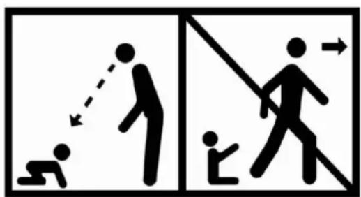
- THE SWIMMING POOL CAN BE A HAZARD TO YOUR CHILDREN. DROWNING MAY HAPPEN VERY QUICKLY. WHEN CHILDREN ARE NEAR THE POOL THEY REQUIRE CONSTANT AND ACTIVE SUPERVISION, EVEN IF THEY ARE ABLE TO SWIM.
- THIS BARRIER DOES NOT REPLACE COMMON SENSE OR INDIVIDUAL RESPONSIBILITY. THE BARRIER CANNOT REPLACE SUPERVISION CARRIED OUT BY RESPONSIBLE ADULTS WHICH STILL REMAINS THE KEY FACTOR IN PROTECTING SMALL CHILDREN.
- POINTS OF ACCESS MUST BE CLOSED SYSTEMATICALLY WHEN NO-ONE IS HOME, EVEN IF IT IS FOR A SHORT PERIOD OF TIME.
- WARNING! SAFETY IS GUARANTEED WHEN POINTS OF ACCESS ARE LOCKED.
- CHECK WHETHER THERE ARE ELEMENTS NEAR THE BARRIER THAT COULD ENABLE OR FACILITATE CLIMBING THE FENCE.
CLOSING POINTS OF ACCESS THROUGH AUTOMATED CLOSING SYSTEMS SHOULD BE CHECKED SYSTEMATICALLY. - WHEN THE BARRIER IS BROKEN OR DAMAGED AND REQUIRES REPAIR WORK, IT IS VERY IMPORTANT TO INCREASE SUPERVISION TO PREVENT SMALL CHILDREN FROM ACCESSING THE POOL.
- LEARN RESCUE TECHNIQUES (CARDIOPULMONARY RESUSCITATION) AND UPDATE YOUR KNOWLEDGE PERIODICALLY. IT COULD SAVE A LIFE IN AN EMERGENCY.
- THE PRESENCE OF PARENTS AND/OR OTHER RESPONSIBLE ADULTS IS REQUIRED WHEN THE POOL IS ACCESSIBLE.
Memorise and put up the telephone numbers of the emergency services near the pool 999. Fire 999
Ambulance 999
Poison centre 02078581228
BARRERA DE PROTECCION PARA PISCINAS
RECOMMANDATIONS IMPORTANTES
9. ACCESSO ALLA PISCINA
UTILIZACAO E MANUTENCAO
9. ACEDER A PISCINA
1.1 In accordance with these provisions, the seller guarantees that the product corresponding to this guarantee ("the Product") is in perfect condition at the time of delivery.
1.2 The Guarantee Term for the Product is two (2) years from the time it is delivered to the purchaser.
1.3 In the event of any defect in the Product that is notified by the purchaser to the seller during the Guarantee Term, the seller will be obliged to repair or replace the Product, at his own cost and wherever he deems suitable, unless this is impossible or unreasonable.
1.4 If it is not possible to repair or replace the Product, the purchaser may ask for a proportional reduction in the price or, if the defect is sufficiently significant, the termination of the sales contract.
1.5 The replaced or repaired parts under this guarantee, will not extend the guarantee period of the original Product, but will have a separate guarantee.
1.6 In order for this guarantee to come into effect, the purchaser must provide proof of the date of purchase and delivery of the Product.
1.7 If, after six months from the delivery of the Product to the purchaser, he notifies a defect in the Product, the purchaser must provide proof of the origin and existence of the alleged defect.
1.8 This Guarantee Certificate is issued without prejudice to the rights corresponding to consumers under national regulations.
2 INDIVIDUAL TERMS
2.1 This guarantee covers the products referred to in this manual.
2.2 This Guarantee Certificate will only be applicable in European Union countries.
2.3 For this guarantee to be effective, the purchaser must strictly follow the Manufacturer's instructions included in the documentation provided with the Product, in cases where it is applicable according to the range and model of the Product.
2.4 When a time schedule is specified for the replacement, maintenance or cleaning of certain parts or components of the Product, the guarantee will only be valid if this time schedule has been followed.
3 LIMITATIONS
3.1 This guarantee will only be applicable to sales made to consumers, understanding by "consumer", a person who purchases the Product for purposes not related to his professional activities.
3.2 The normal wear resulting from using the product is not guaranteed. With respect to expendable or consumable parts, components and/or materials, such as batteries, light bulbs, etc. the stipulations in the documentation provided with the Product, will apply.
3.3 The guarantee does not cover those cases when the Product; (I) has been handled incorrectly; (II) has been repaired, serviced or handled by nonauthorised people or (III) has been repaired or serviced not using original parts. In cases where the defect of the Product is a result of incorrect installation or start-up, this guarantee will only apply when said installation or start-up is included in the sales contract of the Product and has been conducted by the seller or under his responsibility.
ES-CERTIFICADO DE GARANTÍA

- Instruction Manual - Manual de Instrucciones Manuel d'instructions - Bedienungsanleitung Manuale delle instruzioni - Handleiding met instructies Manual de instruções
- CALCULATION OF NECESSARY NUMBER OF MODULES
- CONTENT OF PACKAGE
- REQUIRED TOOLS
- INSTALLATION OF BARRIER
- PROLOGUE
- ESTABLISHING A STARTING POINT
- TRACE THE 4 MARKS TO DESIGNATE THE 4 POLES OF THE FIRST PANEL
- MAKING THE HOLES
- INSTALLATION OF PEGS AND PANEL
- SUBSEQUENT PANELS
- REPEAT STEPS FROM PARAGRAPS 2 TO 5 UNTIL ALL HOLES HAVE BEEN DRILLED AND ALL PANELS HAVE BEEN PLACED.
- ADJUSTING THE LENGTH OF A PANEL
- INSTALLING THE LOCK HOOKS
- USE AND MAINTENANCE
- ACCESS TO THE POOL
- MAINTENANCE
- SAFETY PRECAUTIONS
- BARRERA DE PROTECCION PARA PISCINAS
- RECOMMANDATIONS IMPORTANTES
- ACCESSO ALLA PISCINA
- UTILIZACAO E MANUTENCAO
- ACEDER A PISCINA
- INDIVIDUAL TERMS
- LIMITATIONS
- ES-CERTIFICADO DE GARANTÍA
Brand : GRE
Model : SF133
Category : Pool safety barrier