
ActiveFinder One - Measuring equipment Laserliner - Free user manual and instructions
Find the device manual for free ActiveFinder One Laserliner in PDF.


| Brand | Laserliner |
| Model | ActiveFinder One |
| Product type | Non-contact voltage detector |
| Voltage range | 50 V AC to 1000 V AC |
| Frequency | 50 - 60 Hz |
| Overvoltage category | CAT III - 1000 V |
| Pollution degree | 2 |
| Protection class | II (double insulation) |
| Power supply | 2 AAA 1.5 V batteries (LR03) |
| Dimensions (L x H x D) | 19 x 139 x 25 mm |
| Weight (batteries included) | 48 g |
| Visual indicator | Red/green LED in detector tip |
| Audible indicator | Warning beep |
| Operating temperature | 0°C to 50°C |
| Operating humidity | max. 80% RH (non-condensing) |
| Storage temperature | -10°C to 60°C |
| Maintenance | Clean with damp cloth; avoid solvents |
| Storage | Remove batteries if stored for extended period |
| Main use | Voltage detection in cables, sockets, fuses |
| Safety | Test on known source before use; do not use if damaged |
Frequently Asked Questions - ActiveFinder One Laserliner
User questions about ActiveFinder One Laserliner
0 question about this device. Answer the ones you know or ask your own.
Ask a new question about this device
Download the instructions for your Measuring equipment in PDF format for free! Find your manual ActiveFinder One - Laserliner and take your electronic device back in hand. On this page are published all the documents necessary for the use of your device. ActiveFinder One by Laserliner.
USER MANUAL ActiveFinder One Laserliner
natural_image
White Laserliner medical device with needle and control knob (no visible text or symbols on body)
Laserliner
| DE | 04 |
| EN | 07 |
| NL | 10 |
| DA | 13 |
| FR | 16 |
| ES | 19 |
| IT | 22 |
| PL | 25 |
| FI | 28 |
| PT | 31 |
| SV | 34 |
| NO | 37 |
| TR | 40 |
| RU | |
| UK | |
| CS | |
| ET | |
| LV | |
| LT | |
| RO | |
| BG | |
| EL | |
| SL | |
| HU | |
| SK |
Laserliner
ActiveFinder One
A
B


CAT III
E
F
1 32 4

G
natural_image
Close-up of a white electrical outlet with a plug inserted, showing internal wiring (no text or symbols visible)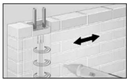
natural_image
Diagram of a brick wall with embedded fixtures and directional arrows indicating movement or force (no text or symbols)H
natural_image
Electrical outlet with a cable and warning symbol (no readable text or labels)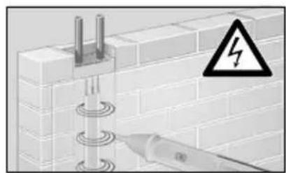
natural_image
Diagram of a cable or wire connection with a warning symbol (no text or labels present)K
CE

Laserliner
!
Completely read through the operating instructions, the „Warranty and Additional Information“ booklet as well as the latest information under the internet link at the end of these instructions. Follow the instructions they contain. This document must be kept in a safe place and passed on together with the device.
Function/Application
Contactless test device for localising electrical voltage (230 V AC) in cables, sockets, lampholders and fuses. Visual and acoustic signals indicate whether a voltage is present.
Safety instructions
- The device must only be used in accordance with its intended purpose and within the scope of the specifications.
- The measuring tools and accessories are not toys. Keep out of reach of children.
- Modifications or changes to the device are not permitted, this will otherwise invalidate the approval and safety specifications.
- Do not expose the device to mechanical stress, extreme temperatures or significant vibration.
- If you are working with voltages higher than 24 V/AC / 60 V/DC, exercise extreme caution. Touching the electrical conductors at such voltages poses a risk of life-threatening electric shocks.
- If the device comes into contact with moisture or other conductive-residue, work must not be carried out under voltage. At and above voltages of 24 V/AC / 60 V/DC, the presence of moisture creates the risk of life-threatening electric shocks.
- Clean and dry the device before use.
- When using the device outdoors, make sure that the weather conditions are appropriate and/or that suitable protection measures are taken.
- In overvoltage category III (CAT III - 1000 V), the voltage between the test device and earth must not exceed 1000 V.
- Before taking any measurements, make sure that both the area to be tested (e.g. a line), the test device and the accessories used (e.g. connection cable) are in proper working order. Test the device by connecting it to known voltage sources (e.g. a 230 V socket in the case of AC testing).
- The device must no longer be used if one or more of its functions fail or the battery charge is weak.
- Observe the safety precautions of local and national authorities relating to the correct use of the device and any prescribed safety equipment (e.g. electrician's safety gloves).
- Do not work alone in the vicinity of hazardous electrical installations and only under the guidance of a qualified electrician.
- The measuring device must not be used as a substitute for a two-pole zero potential test.
Laserliner
- The device measures the presence of electrostatic fields of sufficient strength. If the field strength is too low voltage may still be applied although no warning signal is given. The following list of factors that influence the field strength does not claim to be complete: shielding, cable insulation (type, thickness), measurement distance, insulation between user and earth, special socket designs, condition of tester and of batteries.
Additional information on use
Observe the technical safety regulations for working on electrical systems, especially: 1. Safely isolating from power supply, 2. Securing to prevent system being switched on again, 3. Checking zero potential, two-pole, 4. Earthing and short-circuiting, 5. Securing and covering adjacent live components.
Safety instructions
Dealing with electromagnetic interference
- The measuring device complies with safety and electromagnetic compatibility regulations and limits in accordance with the Low Voltage Directive 2014/35/EU and electromagnetic compatibility regulations in accordance with the EMC Directive 2014/30/EU.
- Local operating restrictions – for example, in hospitals, aircraft, petrol stations or in the vicinity of people with pacemakers – may apply. Electronic devices can potentially cause hazards or interference or be subject to hazards or interference.
Symbols
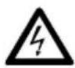
Fig. B: Warning about hazardous electrical voltage: Unprotected live components inside the device housing are capable of posing a risk of electric shock.
Fig. C: Protection class II: The test device has reinforced or double insulation.
Fig. D: Overvoltage category III: Equipment in fixed installations and for applications where specific requirements with regard to the reliability and availability of equipment have to be met, e.g. circuit-breakers in fixed installations and devices used in industrial applications which are permanently connected to the fixed installation.
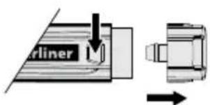
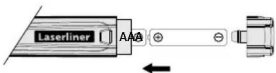
1 Insertion of batteries (see Fig. E)
Open the battery compartment and insert battery according to the symbols. Be sure to pay attention to polarity.
Device description (see Fig. F)
1 Detector tip with LED indicator (green/red) / status indicator
2 ON/OFF
3 Pocket clip
4 Battery compartment

Before using the device, you should always test it on a main circuit you know to be operational within the specified voltage range.
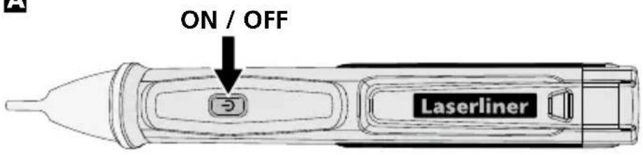
2 ON / OFF (see Fig. A)
3 LED indicator/status indicator
The LED indicator in the detector tip (1) signals the following:
Green LED: Tester ready / off-circuit area
Red LED with alarm: Live wires in vicinity
LED off: Tester not ready
4 Localising electrical voltages
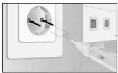
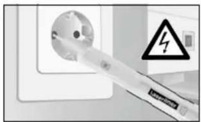
Fig. G: Position the detector tip in the area to be tested (e.g. cable, socket. etc.). Fig. H: When voltage is present, the detector tip lights red and a signal sounds.
For safety, check all three phase conductors (L1, L2, L3) for the presence of voltage!
! Change the batteries when the acoustic signal is weak.
Please be aware that even if a visual signal is not displayed, voltage may still be present. Differences in the design of the connection socket or the nature of the insulation (thickness and type) can affect functionality. Voltage cannot be detected behind panels and metal covers.
Information on maintenance and care
Clean all components with a damp cloth and do not use cleaning agents, scouring agents and solvents. Remove the battery(ies) before storing for longer periods. Store the device in a clean and dry place.
Technical data Subject to technical alterations. Rev18W41
| Indicator LED (red/green) | |
| Voltage range | 50 V AC ~ 1000 V ACFrequency 50 ... 60 Hz |
| Overvoltage category | CAT III - 1000 V (non-condensing)Pollution degree 2 |
| Power supply 2 x 1.5 AAA (NEDA 24A/IEC LR 03) | |
| Operating conditions | 0°C ... 50°C, Max. humidity 80% rH,no condensation,max. altitude 2000 m |
| Storage conditions | -10°C ... 60°C,Max. humidity 80% rH |
| Dimensions (W x H x D) 19 x 139 x 25 mm | |
| Weight (incl. batteries) | 48 g |
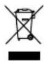
EU directives and disposal (see Fig. K)
This device complies with all necessary standards for the free movement of goods within the EU. This product is an electric device and must be collected separately for disposal according to the European Directive on waste electrical and electronic equipment. Further safety and supplementary notices at:
http://laserliner.com/info?an=action
Laserliner
!
natural_image
Illustration of a white electric shock absorber inserting into a wall socket, with no visible text or symbols.SERVICE

Umarex GmbH & Co. KG
- Laserliner -
- Laserliner
- ActiveFinder One
- !
- Function/Application
- Safety instructions
- Additional information on use
- Symbols
- Insertion of batteries (see Fig. E)
- Device description (see Fig. F)
- ON / OFF (see Fig. A)
- LED indicator/status indicator
- Localising electrical voltages
- Information on maintenance and care
- EU directives and disposal (see Fig. K)
Brand : Laserliner
Model : ActiveFinder One
Category : Measuring equipment