Codix 533 - Measuring equipment Kübler - Free user manual and instructions
Find the device manual for free Codix 533 Kübler in PDF.

| Product Type | Setpoint Generator |
| Brand | Kübler |
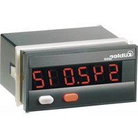
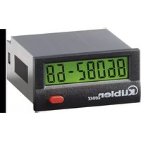
| Model | Codix 533 |
| Display | 4 decades, red 7-segment LEDs, height 8 mm |
| Power Supply | 10 … 30 V DC, galvanic isolation |
| Power Consumption | max. 1 W |
| Current Output | 0 … 24 mA, increment 10 μA, load ≤ 500 Ω (20 mA) or ≤ 400 Ω (24 mA) |
| Voltage Output | 0 … 12 V DC, increment 10 mV, load ≥ 2 kΩ |
| Accuracy | < 0.1 % of final value ± 0.01 %/K |
| Operating Modes | SEtP (standard setpoint), MAn (manual ramp), Auto (automatic ramp) |
| Programming | 2 front panel buttons |
| Hold Input | Optocoupler, active high (low: 0 … 2 V DC, high: 4 … 30 V DC) |
| Operating Temperature | -20 … +65 °C, non-condensing |
| Storage Temperature | -25 … +85 °C, non-condensing |
| Ambient Humidity | 90 % at 25 °C, non-condensing |
| Protection Rating | IP65 front |
| Weight | approx. 50 g |
| Panel Cutout Dimensions | 50 x 25 mm |
| Connection | Screw terminals RM5.08, wire cross-section 0.14 … 1.5 mm² (26 … 16 AWG) |
| Memory | EEPROM for data backup in case of power failure |
| Safety | Use according to EN 61010-1, not in explosive areas |
| Maintenance and Cleaning | No special maintenance, clean with a dry, lint-free cloth |
| Spare Parts and Repairability | Order reference: 6.533.012.300 |
| General Information | Multilingual instruction manual available for download |
Frequently Asked Questions - Codix 533 Kübler
User questions about Codix 533 Kübler
0 question about this device. Answer the ones you know or ask your own.
Ask a new question about this device
Download the instructions for your Measuring equipment in PDF format for free! Find your manual Codix 533 - Kübler and take your electronic device back in hand. On this page are published all the documents necessary for the use of your device. Codix 533 by Kübler.
USER MANUAL Codix 533 Kübler
text_image
max. 19.3 22×45 59 4 6.57: 0 ... 12 V DC (Uout)
text_image
Warning symbol with exclamation mark inside triangleflowchart
graph TD
    A["PE 1"] --> B["0.1 to 9999"]
    A --> C["ou20"]
    C --> D["0 to 9999"]
    C --> E["PE20"]
    E --> F["0.1 to 9999"]
    E --> G["cyc1"]
    G --> H["0 to 9999"]
    H --> I["noCY"]
    I --> J["1sec"]
- MR Number of Perioids
5: 0 ... 24 mA (lout)
6: GND 3
7:0 ... 12 V DC (Uout)
- Functional Description ...... 2
1.1 The SEtP Operating Mode 2
1.2 The MAn Operating Mode 2
1.3 The Auto Operating Mode 2
1.4 Block Diagram. 3
2 Safety Instructions and Warnings 3
2.1 Intended Purpose 4
3 Start-up 4
3.1. Reset, Back to Factory Setting 4
3.2. Programming and Operation of the Setpoint Generator With the 2 Keys .... 4
3.3. General Information about Programming .... 5
4 Programming 5
4.1 Call for the Programming Mode 5
4.2 Programming Mode 5
4.2.1 SEtP Operating Mode 5
4.2.2 MAn Operating Mode 6
4.2.3 Auto Operating Mode 7
4.2.3.1 Example of Auto Operating Mode 10 - Technical Data 11
- Connecting Diagram 11
- Scope of Delivery 11
- Order Information 11
- Error Messages 11
1. Functional Description
This setpoint generator is an easy-to-use microprocessor-controlled device outputting current and voltage values.
Current: 0 ... 24 mA
Voltage: 0 ... 12 V DC.
Only one output can be used at a time.
Three operating modes can be programmed:
- Standard setpoint function
- Manual ramp function
- Automatic ramp operation
Data backup for power failure
The programmed data is saved in an EEprom; it remains saved even in case of a power breakdown.
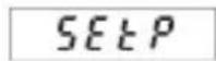
1.1 The SEtP Operating Mode
SELP
In this mode, the device is operated in manual operation after programming: a setpoint is input by means of the keys. The value input here directly in volts or mA, will be the value output by the device.
If no other key is depressed within 3 seconds, the value input will be considered as the new setpoint and will be output by the device.
1.2 The MAn Operating Mode
P78n
In this mode, the device is operated in manual ramp operation after programming: this operation is defined by means of 2 freely selectable current or voltage values and by the increment. During operation, press the right key to increase the setpoint by the increment programmed, press the left key to reduce the setpoint by
this increment. In addition, the device offers the possibility to apply a scale factor to the setpoint output: it is possible to display e.g. 10 (kg) while 2 V are output. During operation, the display alternates between the output setpoint and the message MAn.
1.3 The Auto Operating Mode
Ruto
In this mode, the device is operated in ramp operation after programming: the automatic ramp function is defined by means of a maximum of 20 current or voltage values which are output automatically. The ramp function can be either cyclic or limited. A cycle can be programmed in the range of 0.1 s ... 999.9 s or 0.1 min .... 999.9 min. The automatic
ramp function is started with the right key. It can be ended with the left key. The automatic ramp function can be stopped by activating the Hold input. During operation, the display alternates between the output setpoint and the message Auto.
1.4 Block Diagram
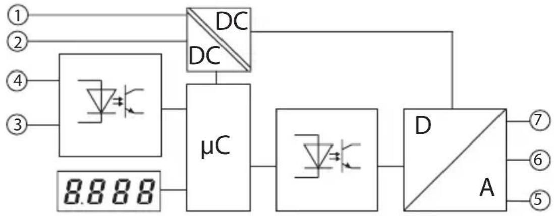
flowchart
graph TD
    A["1"] --> B["μC"]
    C["2"] --> B
    D["3"] --> B
    E["4"] --> B
    F["5"] --> G["A"]
    H["6"] --> G
    I["7"] --> G
    J["DC"] --> B
    K["DC"] --> B
    L["μC"] --> M["μC"]
    N["μC"] --> O["μC"]
    P["D"] --> Q["A"]
    Q --> R["7"]
    Q --> S["6"]
    Q --> T["5"]
Inputs
1: 10 ... 30 V DC 4: Hold
2: GND_1
3: GND\_2
Outputs
5: 0 ... 24 mA (Iout)
6: GND_3
7: 0 ... 12 V DC (Uout)
2 Safety Instructions and Warnings
- Before carrying out any installation or maintenance work, make sure that the power supply of the digital display is switched off.
- Only operate this device according to its intended purpose.
- It must be in perfect technical condition.
- Use this device in accordance with the instructions of the operating manual and the general safety notes.
- Take into consideration the provisions specific to the country of use and to the user.

text_image
Warning symbol image with exclamation mark inside triangle- This device is not suitable for areas subject to explosion hazards, nor for the operating areas excluded in standard EN 61010 Section 1.
- The digital display can only be operated as a properly built-in device, according to the chapter "general technical data".
2.1 Intended Purpose
This device shall only be operated as a built-in device. Its fields of application are industrial processes and controls for manufacturing lines in the metal, wood, plastic, paper, glass and textile industry, and similar applications.
Overvoltages at the screw terminals of the device must be limited at the values of the overvoltage category II.
If the device is used for monitoring machines or process flows, in which a breakdown of the device or an operating mistake might lead to machine damages or operator accidents, the user must take suitable safety measures.
3 Start-up
After powering the device, the following message is displayed for 2 seconds:
Then the device type is displayed for 2 seconds, followed by the software version, also for 2 seconds. After reading the EEPROM, the device switches to the operating mode.
3.1. Reset, Back to Factory Setting
Press both keys simultaneously and power the device: the following message appears on the display:
The device is reset to the factory settings and is now ready for operation.
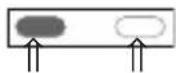
3.2. Programming and Operation of the Setpoint Generator With the 2 Keys
While programming, press both keys simultaneously to switch over to the following parameter.
Within a parameter, confirm an input also by pressing both keys.
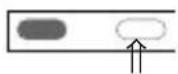
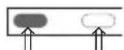
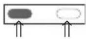
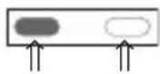
The right key allows selecting the values of the parameters. To input a numerical value, select the decade with the left key
and select a value between 0 ... 9
with the right key.
3.3 General Information about Programming
Note
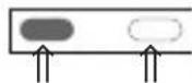
When this manual instructs to press both keys simultaneously, press the left key slightly before the right key;
hold both keys pressed for at least 3 seconds.
4 Programming
4.1 Call for the Programming Mode
To call the programming mode:
- Press simultaneously both front side keys.
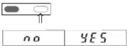
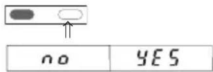
- The following message is displayed

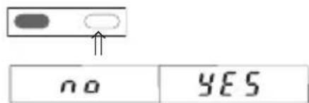
- In addition, a blinking request for confirmation is displayed. Press the right key to switch over between YES and No

- If YES is displayed and both keys are pressed, the programming mode is called for. no exits the programming mode
4.2 Programming Mode
- Press the right key and select the operating mode:
- 3 operating modes are available:

- After selecting the operating mode, press both keys. Programming can start now.
The three operating modes can be programmed independently of each other.
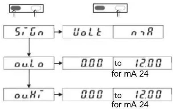
4.2.1 Operating Mode SEtP
- The following parameters can be programmed for the SETP mode:
flowchart
graph TD
    A["Signal"] --> B["Output: Voltage to mA 24"]
    A --> C["Output: Output to mA 24"]
    B --> D["Output: 0.00 to 12.00"]
    C --> E["Output: 0.00 to 12.00"]
- SiGn ^a allows selecting the setpoint output in volts or mA. Press both keys to switch over from SiGn to ou.Lo and ou.HI.
- output.Low allows defining the lowest value.
- output.High allows defining the highest value.
Use the left key to select the decade and the right key to select a value from 0 ... 9.
During operation, it is not possible to define a value lower than the ou.Lo value or higher than the ou.Hi value.
The default value for ou.Lo is 0 V or 0 mA. The default value for ou.Hi is 12 V or 24 mA.
- After setting the value of ou.Hi, press both keys; the following message is displayed:
- Use the right key to select YES or no
text_image
no YES- If YES is selected, press both keys simultaneously to end the programming. The new values are saved in the EEPROM.
-
The device is ready for operation.
-
If, during operation, the operator switches to the programming mode and alters the parameters ou.Lo. or ou.Hi, take into account the following when exiting the programming mode:
If the value of parameter ou.Lo was altered, the output of the device will automatically be set to the value of parameter ou.Lo when it will be set back to operation.
If the value of parameter ou.Hi was altered, the output of the device will automatically be set to the value of parameter ou.Lo when it will be set back to operation.
4.2.2 Operating Mode MAn

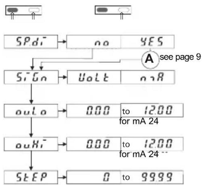
- The following parameters can be programmed for the MAn mode:
flowchart
graph TD
    A["SPd1"] --> B["no"]
    A --> C["YES"]
    B --> D["sign"]
    C --> D
    D --> E["uolt"]
    E --> F["ourLo"]
    F --> G["0.00 to 12.00 for mA 24"]
    G --> H["ouHi"]
    H --> I["0.00 to 12.00 for mA 24"]
    I --> J["STEP"]
    J --> K["0 to 99.99"]
    L["A see page 9"] --> M["Sign"]
2. Functions
- see page 9
- SiGn allows selecting the setpoint output in volts or mA. Press both keys to switch over from SiGn to ou.Lo and ou.HI.
- output.Low allows defining the lowest value.
- output.High allows defining the highest value.
- Step allows defining the increment. During operation, the setpoint output will increase by this value when the right key is pressed. The setpoint output will decrease by this value when the left key is pressed. During operation, if the operator tries to reduce the setpoint below the low limit, the setpoint will be maintained at the value of ou.Lo.
If he tries to exceed the upper limit, the setpoint will be maintained at the value of ou.Hi.
Note
If, during operation, the operator switches to the programming mode and alters the value of ou.Lo, ou.Hi, di.Lo or di.Hi, the parameter StEP will be reset to zero and the output value will be reset to ou.Lo or di.Lo.
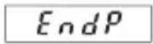
- After setting the value of StEP, press both keys simultaneously; the following message is displayed:
EndP
- Use the right key to select YES or no
text_image
no YES- If YES is selected, press both keys simultaneously to end the programming
- The device is ready for operation.
4.2.3 Operating Mode Auto
Ruto
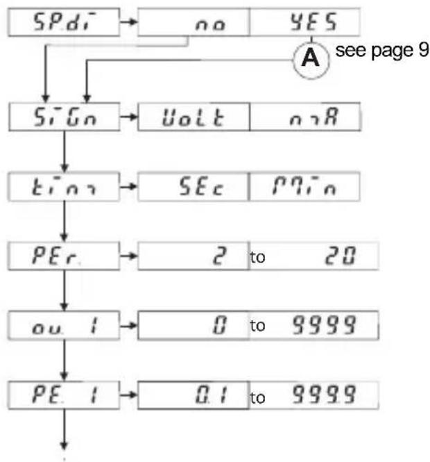
- The following parameters can be programmed for the Auto mode:
flowchart
graph TD
    A["SPd"] --> B["no"]
    B --> C{A see page 9}
    C --> D["Sign"]
    D --> E["Volt"]
    D --> F["onR"]
    E --> G["TEO"]
    F --> H["SEC"]
    H --> I["PPin"]
    G --> J["PEc"]
    J --> K["2 to 20"]
    J --> L["ou 1"]
    L --> M["0 to 9999"]
    J --> N["PE 1"]
    N --> O["0.1 to 9999"]
flowchart
graph TD
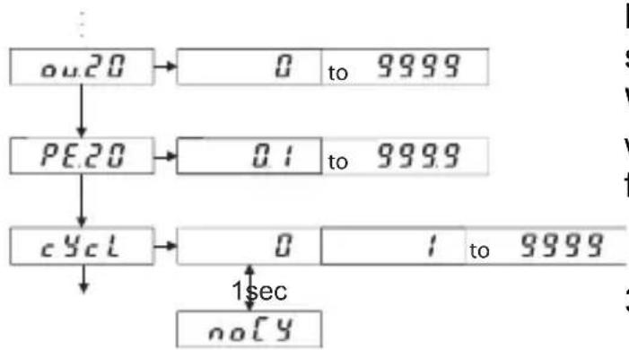
A["ou20"] --> B["0 to 9999"]
A --> C["PE20"]
C --> D["0.1 to 9999"]
C --> E["cyc1"]
E --> F["0 to 9999"]
F --> G["no[4"]]
G --> H["1sec"]
- The function SP_d see page 9
- SiGnal allows selecting the setpoint output in volts or mA.
- time allows selecting the time in seconds or minutes.
- PE r. Number of allows defining the number of reference points.
- ou. i output 1 allows selecting the value of the current or voltage for the first reference point.
- PE 1 PEriod. 1 allows defining the first period. (A maximum of 20 periods may be programmed) The maximum set-points ou. X and the times PE. X result from the setting of PEr.
- cycl The function allows defining the number of cycles to be carried out.
- no(y) Selecting start an endless loop.
Press both keys simultaneously to switch over to the following parameter. Within a parameter, select the decade with the left key and select a value from 0 ... 9 with the right key.
- After setting the value of cYcl, press both keys simultaneously; the following message is displayed:

- Use the right key to select YES or no
text_image
no YESPEriods
- If YES is selected, press both keys simultaneously to end the programming
- The device is now ready for operation. Press the right key to start it and the left key to stop it.
cYcle
Note:
After powering, the device outputs 0.00 mA or 0.00 V. The Auto function does not start automatically. Alter the manual start of the Auto function, the device outputs the value ou.1. After the execution of the cycle, the output remains with the value ou.1.
Complements to points 4.2.2 and 4.2.3
-
If YES was selected for SP.d_i^- , the display can show a value different from the value of the output setpoint.
-
The function SPcial disPlay
flowchart
graph TD
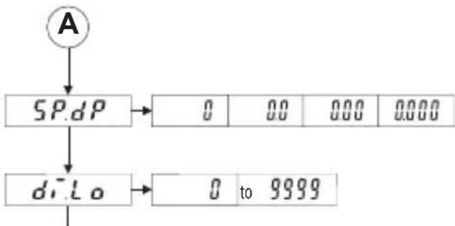
A["A"] --> B["SP.dP"]
B --> C["0 00 000 0000"]
B --> D["d.r.Lo"]
D --> E["0 to 9999"]
- SP.dP The function SPecial(decimalPoint allows defining the number of decimal places (only for the values appearing on the display).
- display.Low allows defining the minimum value to be displayed. This value corresponds to the value ou.Lo used for the
output setpoint.
- d.Hi display.High allows defining the maximum value to be displayed. This value corresponds to the value ou.Hi used for the output setpoint.
Example:
The display must show 10 (kg) while the setpoint output must be 2 V (lower limit value); the display must show 40 (kg) while the setpoint output must be 8 V (upper limit value).
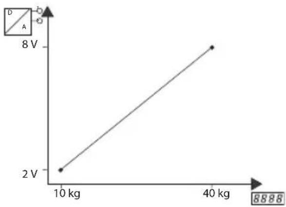
line
| X-axis Label | Y-axis Value | |---|---| | 10 kg | 2 V | | 40 kg | 8 V |- Press both keys to resume programming at point 4.2.1 (1). SiGn, see A in the flow chart
Summary:
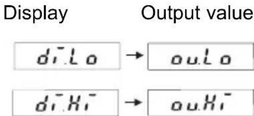
text_image
Display Output value diLo → ouLo diHi → ouHiWhen programming, the values for the display and for the output set-point are linked together.
4.2.3.1 Example of Auto Operating Mode
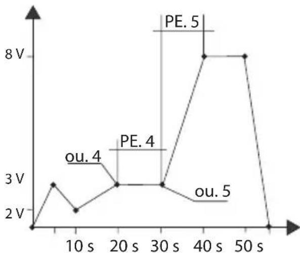
line
| Time (s) | Voltage (V) | | :--- | :--- | | 0 | 2 | | 10 | 3 | | 20 | 3 | | 30 | 3 | | 40 | 8 | | 50 | 8 | | 60 | 2 |The best way to program such a function is to set up a table like the one opposite:
| Example Own values | ||
| PEr 8 | ||
| ou. 1 0 V | ||
| PE. 1 5 s | ||
| ou. 2 3 V | ||
| PE. 2 5 s | ||
| ou. 3 2 V | ||
| PE. 3 10 s | ||
| ou. 4 3 V | ||
| PE. 4 10 s | ||
| ou. 5 3 V | ||
| PE. 5 10 s | ||
| ou. 6 8 V | ||
| PE. 6 10 s | ||
| ou. 7 8 V | ||
| PE. 7 10 s | ||
| ou. 8 0 v | ||
| PE. 8 5 s | ||
5. Technical Data
Display 4-digit red 7-segment LED display, height 8 mm Supply voltage: 10 ... 30 V DC, electrically isolated
Current consumption:39 mA at 25°C, for a 20 mA output current
Power consumption: max. 1 W,
Test voltage: 500 V, 50 Hz., 1 min.
Test voltages:
EN 61010-1 for contamination level 2 and overvoltage category 2
EMC:
Interference emissions EN 55011 Class B Interference immunity EN61000-6-2
Operating temp.:
-20 ... +65 °C, without condensation
Storage temp.:
-25 ... +85 °C, without condensation
Air humidity:
90 % at 25 °C, without condensation
Technical Data (Continued)
Protection: IP 65 front
Weight: approximately 50 g
Inputs: 2 front side keys for setting and programming
Hold input, optocoupler, high active
low: 0 .. 2 VDC / high: 4 .. 30 VDC
Outputs: Current output 0 ... 24 mA, increment 10 μA
Load 20 mA up to ≤ 500 Ohms, > 20 mA up to ≤ 400 Ohms
Ripple: ≤10 mVss
Voltage output 0 ..12 V, increment 10 mV,
Load ≥ 2 kOhms, Ripple: ≤10 mVss
Accuracy: ≤ 0,1 % of the final value ± 0,01 % /K
6. Connecting diagram
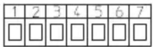
Inputs
1: 10 ... 30 V DC
2: GND_1
3: GND_2
4: Hold
Outputs
5: 0 ... 24 mA (lout)
6: GND_3
7:0 ... 12 V DC (Uout)
Screw terminals RM5.08:
0,14 ... 1,5 mm ^2 , 26 ... 16 AWG
Block diagram and connection see point 1.4
7. Scope of Delivery
1 Digital display
1 Panel mounting clip
1 Bezel for clip mounting, panel cut-out 50 x 25 mm
1 Bezel for screw mounting, panel cut-out 50 x 25 mm
1 Gasket
1 Multilingual operating manual
8. Order Information
Setpoint generator 533:
6.533.012.300
9. Error Messages
Err0: Programming error, e.g.: the value input is above ou.Hi
10. Dimensions, see folding pages
Sommaire
text_image
Warning symbol with exclamation mark inside triangleflowchart
graph TD
    A["ou20"] --> B["0 to 9999"]
    A --> C["PE20"]
    C --> D["0.1 to 9999"]
    C --> E["cyc1"]
    E --> F["0 to 1 sec"]
    F --> G["noCY"]
    G --> H["..."]
Ondulation: ≤10 mVss
7: 0 ... 12 V DC (Uout)
text_image
Warning symbol image with exclamation mark inside triangleflowchart
graph TD
    A["ou20"] --> B["0 to 9999"]
    A --> C["PE20"]
    C --> D["0.1 to 9999"]
    C --> E["cyl"]
    E --> F["0 to 1 sec"]
    F --> G["no["]]
5: 0 ... 24 mA (lout)
6: GND_3
7:0 ... 12 V DC (Uout)
7: 0 ... 12 V DC (Uout)
text_image
Warning symbol with exclamation mark inside triangleflowchart
graph TD
    A["ou20"] --> B["0 to 9999"]
    A --> C["PE20"]
    C --> D["0.1 to 9999"]
    C --> E["cyc1"]
    E --> F["0 to 9999"]
    F --> G["noCY"]
    H["1sec"] --> F
5: 0 ... 24 mA (lout)
6: GND_3
7:0 ... 12 V DC (Uout)
Conexión de rosca RM5.08:
0,14 ... 1,5 mm ^2 , 26 ... 16 AWG