BT3 - Battery charger VOLTCRAFT - Free user manual and instructions
Find the device manual for free BT3 VOLTCRAFT in PDF.
User questions about BT3 VOLTCRAFT
0 question about this device. Answer the ones you know or ask your own.
Ask a new question about this device
Download the instructions for your Battery charger in PDF format for free! Find your manual BT3 - VOLTCRAFT and take your electronic device back in hand. On this page are published all the documents necessary for the use of your device. BT3 by VOLTCRAFT.
USER MANUAL BT3 VOLTCRAFT
Digital Lead Battery Tester BT-3
GB OPERATING INSTRUCTIONS Page 17-28
Copyright 2009 by Voltcraft®
Impressum /legal notice in our operating instructions
These operating instructions are a publication by Voltcraft®, Lindenweg 15, D-92242 Hirschau/Germany, Phone +49 180/586 582 7 (www.voltcraft.de).
All rights including translation reserved. Reproduction by any method, e.g. photocopy, microfilming, or the capture in electronic data processing systems require the prior written approval by the editor. Reprinting, also in part, is prohibited.
These operating instructions represent the technical status at the time of printing. Changes in technology and equipment reserved.
Copyright 2009 by Voltcraft®
Copyright 2009 by Voltcraft®
01_0109_03/HK
These Operating Instructions are intended for this product. They contain important advice for use and handling. Please make sure that they are properly observed, even if the product is given to other persons. Basic knowledge of the use of gauges is assumed.
Please keep these Operating Instructions for later reference!
You can find a list of contents with page numbers on page 19.
In purchasing this Voltcraft® product, you have made a very good decision for which we should like to thank you.
You have acquired an above-average quality product from a brand family which has distinguished itself in the field of measuring, charging and network technology by particular competence and permanent innovation. With Voltcraft®, you will be able to cope even with difficult tasks as an ambitious hobbyist just as much as a professional user. Voltcraft® offers you reliable technology at an extraordinarily favourable cost-performance ratio. We are certain: Your start with Voltcraft will at the same time be the commencement of a long and profitable co-operation. We wish you much enjoyment with your new Voltcraft® product!
With this lead battery tester, you have purchased a product constructed according to latest state of the art. The gauge is equipped with an digital display (gauge) for fast voltage changes and stable clamps for large current loads.
The construction of the lead battery tester fulfills VDE 0411= EN 61010. It has been EMV-tested and fulfils the requirements of valid European and national guidelines. The conformity was proven, the appropriate explanations and documents are defined by the manufacturer. To keep this condition and to guarantee a safe operation, you must as a user observe these operation instructions!
Intended use of the lead battery tester includes:
- Determination of battery status for a 12 V motor vehicle battery to at least 36 Ah with a running measurement (with 100 A).
- running voltage measurement (uncharged) on running engine
- battery voltage measurement (Tester load switch turned off) during ignition
- charge measurements on batteries with ignition on or running engine or attached battery charger are not permitted
-
measurement under adverse conditions is not permitted. Adverse conditions are:
-
strong precipitation such as rain shower or snow
- moisture or high atmospheric humidity (e.g. fog)
-
dust and combustible gasses, vapors (gasoline, diesel or battery acid) or solvents
-
thunderstorms or storm conditions like strong electrostatic fields etc.
Another use than described above is not permitted and leads to the damage of this product. Beyond that there is a risk of hazards, e.g. short-circuit, fire, electrical shock etc. The entire product may not be changed and/or converted! The safety instructions are to be strictly observed!
Safety instructions
Illustration (open side)
- Brackets for battery clamps (pole pliers)
- Cooling holes for power shunt
- LED lights with colours red for "BAD" yellow for "WEAK" i.e. threshold or green for "GOOD"
- 3-digit LED display max. display value 999
- Button "LOAD" to start automatic measuring process
- Pole plier black for minus pole (-) of battery
- Button to set cold start current value (CCA) of battery
- Pole plier red for plus pole (+) of battery

Caution!
Observe maximum input values.
Contents list
Introduction 17
Intended use 18
Adjustable components (end side) 19
List of contents 19
Safety instructions 20
Use of lead battery tester 22
Measurement procedure 22
Disposal 27
Reasons for Error Messages 27
Maintenance 27
Technical Data and Measuring Tolerances 28
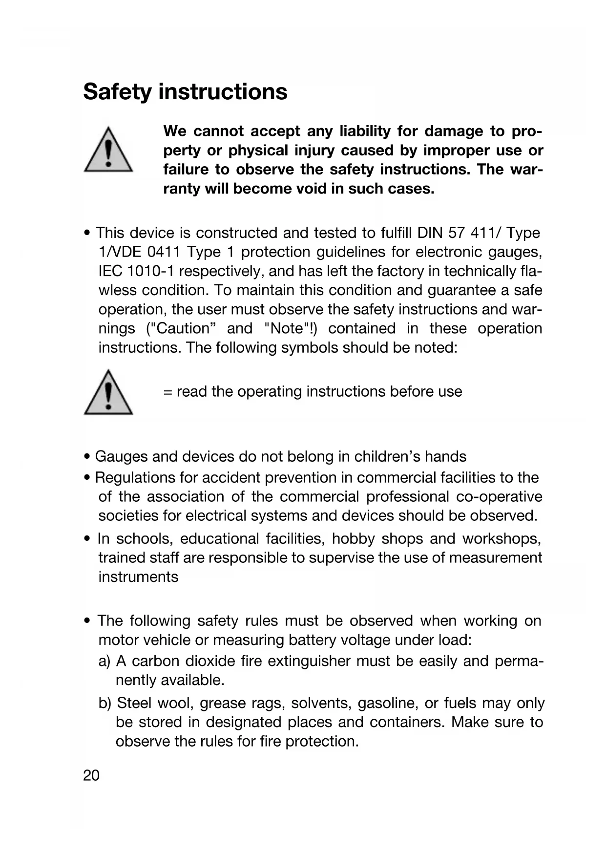
Safety instructions

We cannot accept any liability for damage to property or physical injury caused by improper use or failure to observe the safety instructions. The warranty will become void in such cases.
- This device is constructed and tested to fulfill DIN 57 411/ Type 1/VDE 0411 Type 1 protection guidelines for electronic gauges, IEC 1010-1 respectively, and has left the factory in technically flawless condition. To maintain this condition and guarantee a safe operation, the user must observe the safety instructions and warnings ("Caution" and "Note") contained in these operation instructions. The following symbols should be noted:

= read the operating instructions before use
- Gauges and devices do not belong in children's hands
- Regulations for accident prevention in commercial facilities to the of the association of the commercial professional co-operative societies for electrical systems and devices should be observed.
- In schools, educational facilities, hobby shops and workshops, trained staff are responsible to supervise the use of measurement instruments
- The following safety rules must be observed when working on motor vehicle or measuring battery voltage under load:
a) A carbon dioxide fire extinguisher must be easily and permanently available.
b) Steel wool, grease rags, solvents, gasoline, or fuels may only be stored in designated places and containers. Make sure to observe the rules for fire protection.
c) When working in the engine compartment, wear safety glasses and protective gloves to protect your eyes and hands from battery acid, gasoline, dust, airborne particles and loose machine parts
d) Never look into the exhaust pipes of carburetor when the engine is running, since flames can be expected from backfires, misfires, flames it is a flame at a setback, wrong mis-aligned or defective valves from the exhaust pipes.
e) When the motor is running, never touch rotating parts such as the ventilator, drive-belts, disc-belts, etc. If you have long hair, wear a hairnet. Do not work with loose clothing and/or neckties if the motor is running.
f) No load measurements (toggle switch switched off) with a running engine!!
g) Do not wear any jewelry such as necklaces, rings (also earrings), or watches etc. carbon monoxide gas (co. gas) leaving perhaps (at the burning arising)
h) Ensure sufficient ventilation (garage or workshop) is unconditional worries for you extremely poisonously).
i) Avoid contact with the exhaust and cooling systems. Risk of burning! Never open the radiator cap of a running or hot engine.
k) Make sure that your vehicle is braked (engaged parking brake), no gear is engaged, and that the vehicle is in "park" with vehicles having automatic transmissions.
l) Do not smoke when making measurements or working on the motor vehicle battery! Solvent vapors and hydrogen gas at the charging of lead acid batteries are extremely explosive gasoline!
m) Do not leave any tools lying on the battery. Also do not place the gauge on the battery under any circumstances. Short-circuit hazard! Avoid contact with battery acid. The corrosive acid can seriously damage your clothing and "corrode" your skin or eyes. When measuring an external/deconstructed battery, the gauge must be held at a distance of at least 0.5~m ( = 50~cm ) above the ground.
- If it is ascertained that safe operation is no longer possible, then the device should be taken out of operation and secured against accidental operation. Pull out power supply plugs from the plug socket, cigarette lighter line mark!
It is ascertained that safe operation is no longer possible, if the device shows visible damage
the device does not work any longer
after longer storage under unfavourable conditions, or
after heavy transport stresses
Never switch the device on right away if it was taken in from a cold area to a warm area. The condensation developing as a result can sometimes destroy the device. Let the switched-off device come to room temperature. Wait for the condensation to evaporate.
Use of the lead battery tester

Caution!
Never operate the lead battery tester in the open air. Caution! Always use only the measurement cables attached tightly for your measurements. Pay attention to the undamaged isolation of the cables and the terminal clamps before every putting into pole pliers.
Measurement procedure
A Setting the cold start current value of battery
Prior to measuring, the cold start current value (CCA = Cold Cranking Ampere) of the battery has to be set at the measuring device. Normally, this value is stated on the battery. If this value is not stated, it can be requested from the dealer/manufacturer. If the value cannot be found out, the following recommended values can be
used: car batteries (36 - 100 Ah): 500 - 800 CCA, car batteries (> 100 Ah): 800 - 999 CCA, solar batteries: 300 - 500 CCA
Proceed as follows to set the cold start current value:
- Connect the black pole plier (6) to the minus and the red pole plier (8) to the plus pole of the battery to be checked. Jog carefully at the pliers to ensure a safe contact.
- By pressing the button "SET CCA" (7) the cold start current value can be set. This is preset to 500 CCA and each press of the button changes it.
B Battery Endurance Testing
This test detects whether the battery has enough capacity to start the motor reliably, even under unfavourable climatic conditions. We put a load of approx. 100 A on the battery while measuring. The battery is all right if the battery voltage is relatively constant at >12V while measuring (ca. 10 sec). The battery is both defect or overdischarged if the voltage collapses within a very short period of time. Proceed as follows for the measurement:
- Stop the motor, switch off all consumers (except for clock or the car radio's storage) and remove the ignition key.
- Connect the pole pliers to the battery and set the current value for a cold start. (see point "A. Setting the cold start current value of battery").
- A connection with the correct polarity displays the "idle voltage" of the battery. If the battery voltage is below ca. 12.0V , charge the battery before performing an endurance test.
If no current value of >12.0V is displayed after recharging, the battery is already damaged. If no display follows, maybe one of the pole pliers is loose, has no contact or the battery voltage is below ca. 7.5V .
- Shortly press the "LOAD" (5) button once, the relay picks up and the endurance testing is started. "-L-" is displayed when the measuring process starts with a battery voltage < 12V . The battery should be recharged and the test repeated. After approx. 10 seconds a signal is heard to confirm the end of the measuring
process. Simultaneously, the battery state is displayed via three LED's (green, yellow or red). If in display (4) "-L-" is shown the battery voltage sank below 7.5V during the test.
- Please observe the following table, it shows the different battery conditions:
| LED Display Battery status display: | |
| green LED The illuminated | battery is insufficiently charged. |
| yellow LED The illuminated This | battery is insufficiently charged. battery is either empty or defective. If it is a conventional maintenance-free battery, determine the acid density for battery with an acid pipette, (for at least 1.20 to 1.22 kg/l). The value remains under approx. 1.24 kg/l after charging. The battery is used up (after approx. 5 to 8 years) and must be replaced. |
| red LED The battery is possibly defective or seriously undercharged and should be replaced. | |

Caution!
During the test, the upper unit cover of the tester gets very hot (with the cooling holes (2)). Let the tester cool down for at least a minute before you perform a further test. Never perform more than 3 test within 5 minutes.
C Charging voltage measurement (headlight test)
The charging system of the motor vehicle is tested with this measurement. A sustained under or overcharging of the motor vehicle battery will inevitably lead to damage. The charge test should be performed (described above) before this test. If the battery is OK, you can continue the measurement.

Caution!
The engine should be at operating temperature.
Proceed as follows:
- Attach the pole pliers (+) to the positive terminal (+) of the battery and the black, isolated clamp to the negative terminal (-) of the battery. Gently shake the pole pliers at the terminal to ensure contact.
- switch off all power loads (lights, fans, discs, boosters, etc.), start the engine and hold at a slowing increasing idle speed of approx. 1500 RPM.
- never press the button "LOAD" (5) during this measurement
- read the voltage value on the digital display
- now turn on the high-beam headlights and set your fans to the highest level. The voltage display should change no more than around approx. 0.1 to 0.3 volts (V).
If the display remains relatively stable, the charging system of your motor vehicle is OK. If the voltage changes to more than approx. 0.3 V (above or below), you have your charging electrical equipment (headlights, regulators, brushes, drive-belts, cables, points, cables, plug connector etc.) examined by a mechanic.
D Starter test
With this test, it can be determined relatively easily whether your vehicle starter does not take enough current from the battery. Currents of more than approx. 200 Amp can be produced. Make absolutely sure that the battery is correct before this test. If the battery is weak or defective, then this test is not useful. Proceed as follows:
- Attach the pole pliers polarity with the insulated terminals of the battery and gently shake the pole pliers for a secure contact (upper oxidation "scratched-off").
- Please observe the following table. It specifies the minimum voltage of the battery, during start process with the starter (lower line = cranking) activated or without starter (upper line). However, the values depend strongly on the vehicle type, cylinder capacity etc. The table's specifications apply for vehicles with a cylinder capacity lower or equal to 3600 cc. For motors with more than 3600 cc, take the nearest lower voltage value
- the machine (engine) and read the voltage value during the starting process.
Compare the value with the following table. If the value is substantially lower than the "cranking" voltage, either the starter is defective or there is a bad cable connection (transmission resistance) or the battery is too small (under-sized) for the motor vehicle.
Example: The on-load voltage without starter is 11.0V . During start, the voltage collapses to approx. 10.6V . The motor's cylinder capacity is 3600~cc or less. If the cylinder capacity lies above this value, the voltage may not collapse below 10.3V^ (larger starter currents / performance).
Additional information about lead batteries!
- The starting power (capacity) of a fully-charged battery drops to under 70% at minus temperatures.
- Most damage to lead batteries comes from overcharging.
- "Warm" batteries are fully-charged at a faster rate than cold batteries.
-
every battery loses its charge. The discharge current is lowest with maintenance-free batteries.
-
a battery that has remained uncharged over a long time period, will sulphurize very easily (sulfur deposits on the plates) and will lose capacity as a result.
- a charged fault-free battery has a no-load voltage of 12.7V or more. A defective or uncharged battery has a no-load voltage of 10.5V or less.
Disposal
Dispose the unusable, irreparable lead battery tester in accordance with valid laws.
Reasons for Error Messages:
| Er 2 is shown if the relay contact of the charge relay is not open and will release a tone signal. Disconnect the battery tester from the battery to prevent an overload. Knock with a screwdriver on the hexagon nut at the battery tester's rear to release the strucked relay. If the relay does not unscrew, the battery tester must no longer be used for charge measurements. Have the device repaired in a technical shop. | |
| Er 1 is shown if the relay contact of the charge relay is not open and will release a tone signal. The resistance is probably too high or the control is defective. Have the device repaired in a technical shop. |
Maintenance
The lead battery tester is maintenance-free except for occasional cleaning of the clamps and unit cover. It may not be opened under
any circumstances. If the lead battery tester is nevertheless opened or modified, the warranty claim expires. Use a clean, lint-free, static-free and dry cleaning cloth for cleaning the device.

Caution!
Do not use any carbon-containing cleaning agent, gasoline, alcohol or similar for cleaning. This will affect the casing of the gauge. In addition, the fumes are noxious and explosive. Also do not use any sharp tools, screwdrivers, metal brushes or similar for cleaning.
Technical data and measurement tolerances
Technical data
Display: : 3 digit LED display up to 999, 14 mm resolution
Test current : approx. 100A± 5% at 13.2V
Voltage measurement : approx. 7.5 to max. approx. 25 VDC range (direct voltage)
Running voltage range : approx. 7.5 to max. approx. 16 VDC
Charge (test) time : 10s average
Red LED less than : 9.1 VDC
Yellow LED from : 9.1 to 10.7 VDC
Green LED : 10.8 VDC
Overcharging switch : at approx. 17 VDC
Measuring exactitude : approx. 1 s
Operating temperature: 0^ to +55^
Storage temperature: -20^ to +70^
Relative humidity : max. 80% , non-condensing
Mass : approx. 1.3 kg
Dimensions (L X W X H): approx. 285 x 107 x 75 mm
(without wires)
F Introduction
Cher(e) client(e),