
MEB3200 - Sewing machine JUKI - Free user manual and instructions
Find the device manual for free MEB3200 JUKI in PDF.
User questions about MEB3200 JUKI
0 question about this device. Answer the ones you know or ask your own.
Ask a new question about this device
Download the instructions for your Sewing machine in PDF format for free! Find your manual MEB3200 - JUKI and take your electronic device back in hand. On this page are published all the documents necessary for the use of your device. MEB3200 by JUKI.
USER MANUAL MEB3200 JUKI
natural_image
Line drawing of a sewing machine on a workbench with no visible text or symbols| NOTE: Congratulations on your purchase of a JUKI sewing machine.Read safety instructions carefully and understand them before using.Retain this Instruction Manual for future reference. |
| HINWEIS: Herzlichen Glückwunsch zu Ihrem Kauf einer JUKI-Nähmaschine.Lesen Sie die Sicherheitsanweisungen aufmerksam durch, um sich mit ihnen vertraut zu machen, bevor Sie diese Maschine in Betrieb nehmen.Bewahren Sie diese Bedienungsanleitung für spätere Bezugnahme auf. |
| REMARQUE: Félicitations pour votre achat d'une machine à coudre JUKI.Avant d'utiliser la machine, lire attentivement toutes les consignes de sécurité.Conserver ce manuel pour pouvior le consulter en cas de besoin. |
| NOTA: Nuestro agradecimiento y felicitaciones por su compra de esta máquina de coser JUKI.Antes de comenzar a usar esta máquina lea con detención hasta comprender todas las instrucciones de seguridad.Conserve este Manual de instrucciones a mano para futuras consultas. |
| NOTA: Congratulazioni per l'acquisto di una macchina per cucire JUKI.Leggere attentamente e compredere tutte le istruzioni per la sicurezza prima di inziare l'uso di questa macchina.Conservare questo Manuale d'Instruzioni per pronto riferimento. |
| 注意: 感谢您购买本公司的产品。为了安全地使用,请您在使用之前一定阅读本使用说明书。另外,请您注意保管本使用说明书,以便随时查阅。 |
ENGLISH
TO ENSURE SAFE USE OF YOUR SEWING MACHINE
For the sewing machine, automatic machine and ancillary devices (hereinafter collectively referred to as "machine"), it is inevitable to conduct sewing work near moving parts of the machine. This means that there is always a possibility of unintentionally coming in contact with the moving parts. Operators who actually operate the machine and maintenance personnel who are involved in maintenance and repair of the machine are strongly recommended to carefully read to fully understand the following SAFETY PRECAUTIONS before using/maintaining the machine. The content of the SAFETY PRECAUTIONS includes items which are not contained in the specifications of your product.
The risk indications are classified into the following three different categories to help understand the meaning of the labels. Be sure to fully understand the following description and strictly observe the instructions.
( I ) Explanation of risk levels
 | DANGER :This indication is given where there is an immediate danger of death or serous injury if the person in charge or any third party mishandles the machine or does not avoid the dangerous situation when operating or maintaining the machine. |
 | WARNING :This indication is given where there is a potentiality for death or serious injury if the person in charge or any third party mishandles the machine or does not avoid the dangerous situation when operating or maintaining the machine. |
 | CAUTION :This indication is given where there is a danger of medium to minor injury if the person in charge or any third party mishandles the machine or does not avoid the dangerous situation when operating or maintaining the machine. |
 | Items requiring special attention. |
(II) Explanation of pictorial warning indications and warning labels
| Pictorial warning indication |  | There is a risk of injury if contacting a moving section. | Pictorial warning indication | Be aware that holding the sewing machine during operation can hurt your hands. | |
 | There is a risk of electrical shock if contacting a high-voltage section. | There is a risk of entanglement in the belt resulting in injury. | |||
 | There is a risk of a burn if contacting a high-temperature section. | There is a risk of injury if you touch the button carrier. | |||
 | Be aware that eye deficiency can be caused by looking directly at the laser beam. | Indication label | The correct direction is indicated. | ||
 | There is a risk of contact between your head and the sewing machine. | Connection of a earth cable is indicated. |
| Warning label | 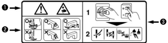 1• There is the possibility that slight to serious injury or death may be caused.• There is the possibility that injury may be caused by touching moving part.2• To perform sewing work with safety guard.• To perform sewing work with safety cover.• To perform sewing work with safety protection device.3• Be sure to turn the power OFF before carrying out "machine-head threading", "needle changing", "bobbin changing" or "oiling and cleaning". 1• There is the possibility that slight to serious injury or death may be caused.• There is the possibility that injury may be caused by touching moving part.2• To perform sewing work with safety guard.• To perform sewing work with safety cover.• To perform sewing work with safety protection device.3• Be sure to turn the power OFF before carrying out "machine-head threading", "needle changing", "bobbin changing" or "oiling and cleaning". | 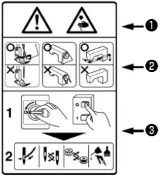 |
| Electrical-shock danger label | 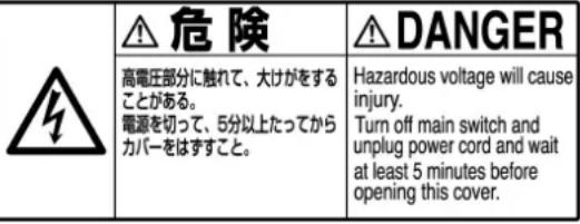 |

DANGER
- When it is necessary to open the control box containing electrical parts, be sure to turn the power off and wait for five minutes or more before opening the cover in order to prevent accident leading to electrical shock.

CAUTION
Basic precaution
- Be sure to read the instruction manual and other explanatory documents supplied with accessories of the machine before using the machine. Carefully keep the instruction manual and the explanatory documents at hand for quick reference.
- The content of this section includes items which are not contained in the specifications of your product.
- Be sure to wear safety goggles to protect against accident caused by needle breakage.
- Those who use a heart pacer have to use the machine after consultation with a medical specialist.
Safety devices and warning labels
- Be sure to operate the machine after verifying that safety device(s) is correctly installed in place and works normally in order to prevent accident caused by lack of the device(s).
- If any of the safety devices is removed, be sure to replace it and verify that it works normally in order to prevent accident that can result in personal injury or death.
- Be sure to keep the warning labels adhered on the machine clearly visible in order to prevent accident that can result in personal injury or death. If any of the labels has stained or come unstuck, be sure to change it with a new one.
Application and modification
- Never use the machine for any application other than its intended one and in any manner other than that prescribed in the instruction manual in order to prevent accident that can result in personal injury or death. JUKI assumes no responsibility for damages or personal injury or death resulting from the use of the machine for any application other than the intended one.
- Never modify and alter the machine in order to prevent accident that can result in personal injury or death. JUKI assumes no responsibility for damages or personal injury or death resulting from the machine which has been modified or altered.
Education and training
- In order to prevent accident resulting from unfamiliarity with the machine, the machine has to be used only by the operator who has been trained/educated by the employer with respect to the machine operation and how to operate the machine with safety to acquire adequate knowledge and operation skill. To ensure the above, the employer has to establish an education/training plan for the operators and educate/train them beforehand.
Items for which the power to the machine has to be turned off
Turning the power off: Turning the power switch off, then removing the power plug from the outlet. This applies to the following.
- Be sure to immediately turn the power off if any abnormality or failure is found or in the case of power failure in order to protect against accident that can result in personal injury or death.
- To protect against accident resulting from abrupt start of the machine, be sure to carry out the following operations after turning the power off. For the machine incorporating a clutch motor, in particular, be sure to carry out the following operations after turning the power off and verifying that the machine stops completely.
2-1. For example, threading the parts such as the needle, looper, spreader etc. which have to be threaded, or changing the bobbin.
2-2. For example, changing or adjusting all component parts of the machine.
2-3. For example, when inspecting, repairing or cleaning the machine or leaving the machine. - Be sure to remove the power plug by holding the plug section instead of the cord section in order to prevent electrical-shock, earth-leakage or fire accident.
- Be sure to turn the power off whenever the machine is left unattended between works.
- Be sure to turn the power off in the case of power failure in order to prevent accident resulting of breakage of electrical components.
PRECAUTIONS TO BE TAKEN IN VARIOUS OPERATION STAGES
Transportation
- Be sure to lift and move the machine in a safe manner taking the machine weight in consideration. Refer to the text of the instruction manual for the mass of the machine.
- Be sure to take sufficient safety measures to prevent falling or dropping before lifting or moving the machine in order to protect against accident that can result in personal injury or death.
- Once the machine has been unpacked, never re-pack it for transportation to protect the machine against breakage resulting from unexpected accident or dropping.
Unpacking
- Be sure to unpack the machine in the prescribed order in order to prevent accident that can result in personal injury or death. In the case the machine is crated, in particular, be sure to carefully check nails. The nails have to be removed.
- Be sure to check the machine for the position of its center of gravity and take it out from the package carefully in order to prevent accident that can result in personal injury or death.
Installation
(I) Table and table stand
- Be sure to use JUKI genuine table and table stand in order to prevent accident that can result in personal injury or death. If it is inevitable to use a table and table stand which are not JUKI genuine ones, select the table and table stand which are able to support the machine weight and reaction force during operation.
- If casters are fitted to the table stand, be sure to use the casters with a locking mechanism and lock them to secure the machine during the operation, maintenance, inspection and repair in order to prevent accident that can result in personal injury or death.
(II) Cable and wiring
- Be sure to prevent an extra force from being applied to the cable during the use in order to prevent electrical-shock, earth-leakage or fire accident. In addition, if it is necessary to cable near the operating section such as the V-belt, be sure to provide a space of 30 mm or more between the operating section and the cable.
- Be sure to avoid starburst connection in order to prevent electrical-shock, earth-leakage or fire accident.
- Be sure to securely connect the connectors in order to prevent electrical-shock, earth-leakage or fire accident. In addition, be sure to remove the connector while holding its connector section.
(III) Grounding
- Be sure to have an electrical expert install an appropriate power plug in order to prevent accident caused by earth-leakage or dielectric strength voltage fault. In addition, be sure to connect the power plug to the grounded outlet without exceptions.
- Be sure to ground the earth cable in order to prevent accident caused by earth leakage.
(IV) Motor
- Be sure to use the specified rated motor (JUKI genuine product) in order to prevent accident caused by burnout.
- If a commercially available clutch motor is used with the machine, be sure to select one with an entanglement preventive pulley cover in order to protect against being entangled by the V-belt.
Before operation
- Be sure to make sure that the connectors and cables are free from damage, dropout and looseness before turning the power on in order to prevent accident resulting in personal injury or death.
- Never put your hand into the moving sections of the machine in order to prevent accident that can result in personal injury or death. addition, check to be sure that the direction of rotation of the pulley agrees with the arrow shown on pulley.
- If the table stand with casters is used, be sure to secure the table stand by locking the casters or with adjusters, if provided, in order to protect against accident caused by abrupt start of the machine.
During operation
- Be sure not to put your fingers, hair or clothing close to the moving sections such as the handwheel, hand pulley and motor or place something near those sections while the machine is in operation in order to prevent accident caused by entanglement that can result in personal injury or death.
- Be sure not to place your fingers near the surround area of the needle or inside the thread take-up lever cover when turning the power on or while the machine is in operation in order to prevent accident that can result in personal injury or death.
- The machine runs at a high speed. Never bring your hands near the moving sections such as looper, spreader, needle bar, hook and cloth trimming knife during operation in order to protect your hands against injury. In addition, be sure to turn the power off and check to be sure that the machine completely stops before changing the thread.
-
Be careful not to allow your fingers or any other parts of your body to be caught between the machine and table when removing the machine from or replacing it on the table in order to prevent accident that can result in personal injury or death.
-
Be sure to turn the power off and check to be sure that the machine and motor completely stop before removing the belt cover and V-belt in order to prevent accident caused by abrupt start of the machine or motor.
- If a servomotor is used with the machine, the motor does not produce noise while the machine is at rest. Be sure not to forget to turn the power off in order to prevent accident caused by abrupt start of the motor.
- Never use the machine with the cooling opening of the motor power box shielded in order to prevent fire accident by overheat.
Lubrication
- Be sure to use JUKI genuine oil and JUKI genuine grease to the parts to be lubricated.
- If the oil adheres on your eye or body, be sure to immediately wash it off in order to prevent inflammation or irritation.
- If the oil is swallowed unintentionally, be sure to immediately consult a medical doctor in order to prevent diarrhea or vomiting.
Maintenance
- In prevention of accident caused by unfamiliarity with the machine, repair and adjustment has to be carried out by a service technician who is thoroughly familiar with the machine within the scope defined in the instruction manual. Be sure to use JUKI genuine parts when replacing any of the machine parts. JUKI assumes no responsibility for any accident caused by improper repair or adjustment or the use of any part other than JUKI genuine one.
- In prevention of accident caused by unfamiliarity with the machine or electrical-shock accident, be sure to ask an electrical technician of your company or JUKI or distributor in your area for repair and maintenance (including wiring) of electrical components.
- When carrying out repair or maintenance of the machine which uses air-driven parts such as an air cylinder, be sure to remove the air supply pipe to expel air remaining in the machine beforehand, in order to prevent accident caused by abrupt start of the air-driven parts.
- Be sure to check that screws and nuts are free from looseness after completion of repair, adjustment and part replacement.
- Be sure to periodically clean up the machine during its duration of use. Be sure to turn the power off and verify that the machine and motor stop completely before cleaning the machine in order to prevent accident caused by abrupt start of the machine or motor.
- Be sure to turn the power off and verify that the machine and motor stop completely before carrying out maintenance, inspection or repair of the machine. (For the machine with a clutch motor, the motor will keep running for a while by inertia even after turning the power off. So, be careful.)
- If the machine cannot be normally operated after repair or adjustment, immediately stop operation and contact JUKI or the distributor in your area for repair in order to prevent accident that can result in personal injury or death.
- If the fuse has blown, be sure to turn the power off and eliminate the cause of blowing of the fuse and replace the blown fuse with a new one in order to prevent accident that can result in personal injury or death.
- Be sure to periodically clean up the air vent of the fan and inspect the area around the wiring in order to prevent fire accident of the motor.
Operating environment
- Be sure to use the machine under the environment which is not affected by strong noise source (electromagnetic waves) such as a high-frequency welder in order to prevent accident caused by malfunction of the machine.
- Never operate the machine in any place where the voltage fluctuates by more than "rated voltage ± 10% in order to prevent accident caused by malfunction of the machine.
- Be sure to verify that the air-driven device such as an air cylinder operates at the specified air pressure before using it in order to prevent accident caused by malfunction of the machine.
- To use the machine with safety, be sure to use it under the environment which satisfies the following conditions:
bent temperature during operation 5°C to 35°C
Relative humidity during operation 35% to 85%
- Dew condensation can occur if bringing the machine suddenly from a cold environment to a warm one. So, be sure to turn the power on after having waited for a sufficient period of time until there is no sign of water droplet in order to prevent accident caused by breakage or malfunction of the electrical components.
- Be sure to stop operation when lightning flashes for the sake of safety and remove the power plug in order to prevent accident caused by breakage or malfunction of the electrical components.
- Depending on the radio wave signal condition, the machine may generate noise in the TV or radio. If this occurs, use the TV or radio with kept well away from the machine.
- In order to ensure the work environment, local laws and regulations in the country where the sewing machine is installed shall be followed.
In the case the noise control is necessary, an ear protector or other protective gear should be worn according to the applicable laws and regulations. - Disposal of products and packages and treatment of used lubricating oil should be carried out properly according to the relevant laws of the country in which the sewing machine is used.
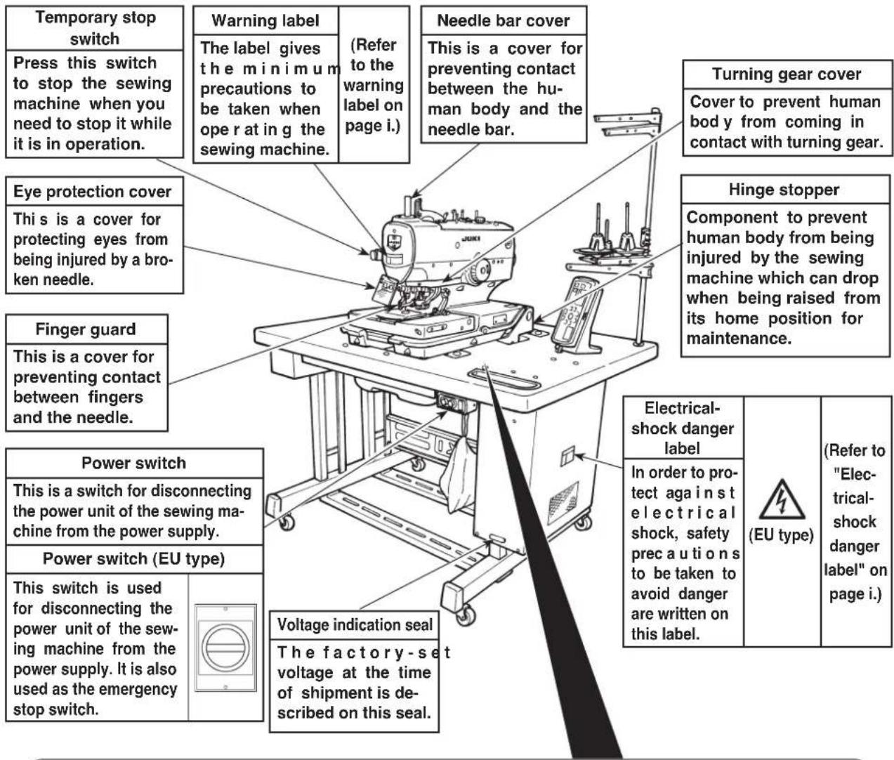
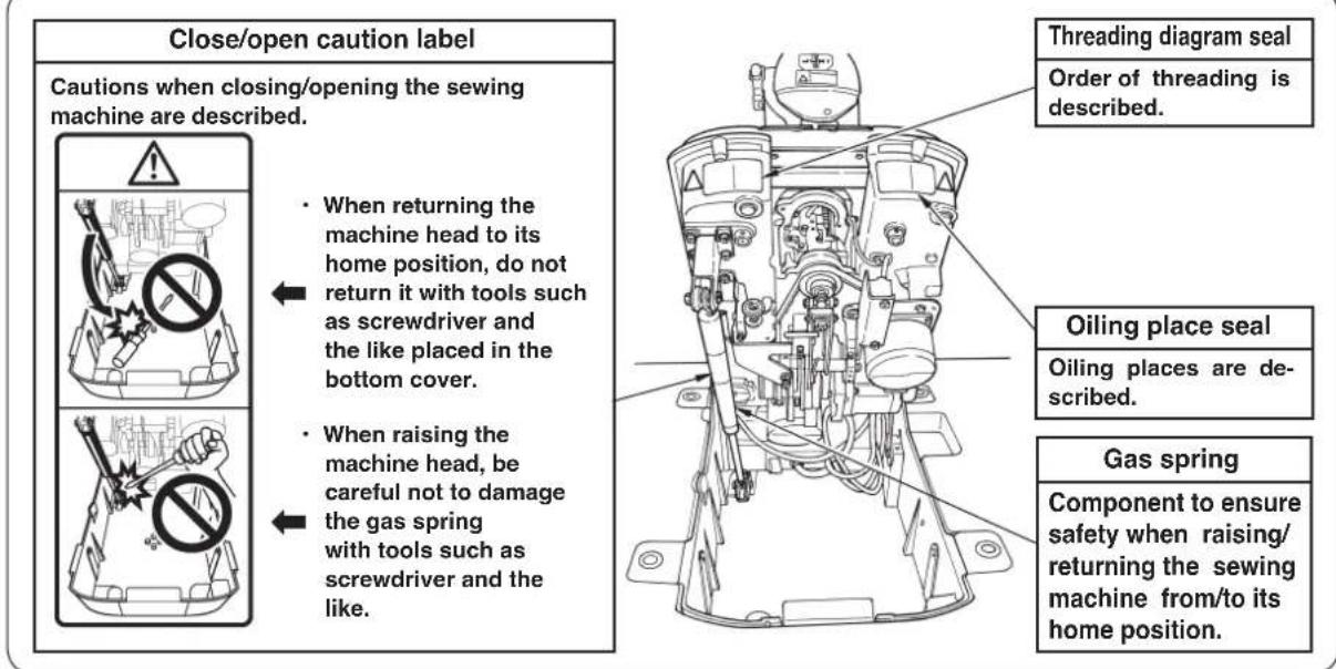
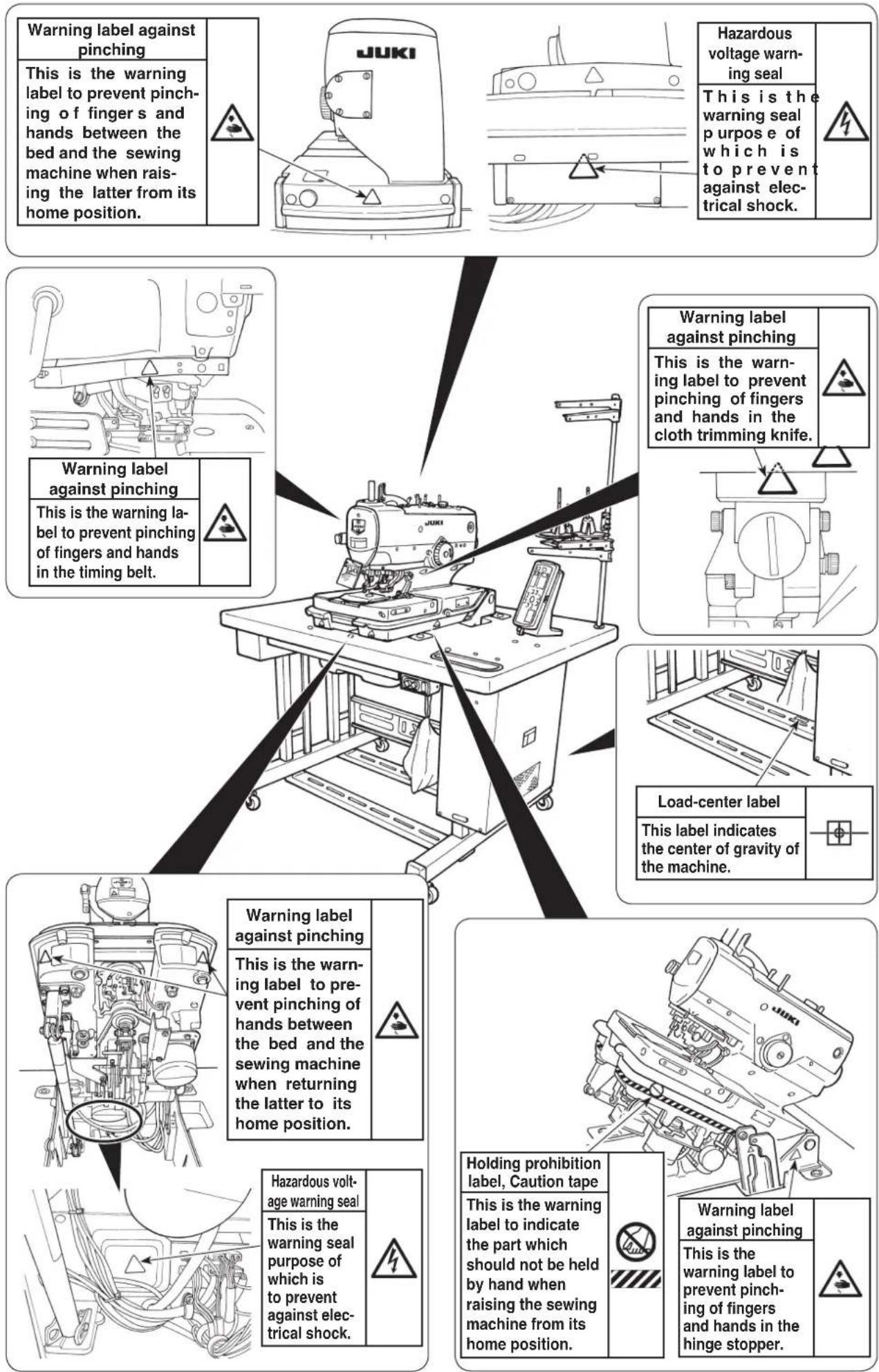
Precautions to be taken so as to use the MEB-3200 more safely
 DANGER DANGER | 1. To prevent accidents caused by electric shock, never open the control box cover or touch the components inside the control box while the power switch is ON.2. If you find the sewing machine is too heavy to lift, the gas spring may have malfunctioned due to outgassing.Never lift the sewing machine in such a state since the machine can drop to pinch hands, fingers and arms resulting in serious injury.3. There is a risk of personal injury if you lift the sewing machine when the gas spring does not function since it is very heavy.* Be sure to fully understand the standard of replacing time of the gas spring on p.56 and its replacement procedure on p.57 before putting the sewing machine into operation.4. Do not raise/return the sewing machine from/to its home position with two or more workers in order to prevent an accident that can result in personal injury.5. Do not hold the sewing machine in its raised position by hand in order to prevent an accident that can result in personal injury.* Be sure to lock the hinge stopper when raising the sewing machine to firmly secure the machine in its raised position.6. Do not hold any part of the sewing machine other than the rib on the bed periphery on the near side in order to prevent an accident that can result in personal injury.7. Do not use the sewing machine when the gas spring is not installed, in order to prevent an accident that can result in personal injury.8. The cloth trimming knife trims the material with an extremely strong pressure.Never allow hands and fingers to move near the cloth trimming knife when the cloth trimming hammer is in operation in order to prevent a pinching accident that can result in personal injury. |
 WARNING WARNING | 1. To avoid personal injuries, when returning the machine head from the raised state to the home position, return it to the home position after confirming that there is no tool or component under the gas spring.2. To avoid personal injuries or damage of the sewing machine, take care not to allow the tool or components to damage the rod section of gas spring in the bottom cover.3. To avoid personal injuries, immediately replace the gas spring with a new one when the rod section of gas spring does not function properly with a flaw or the like, or it is judged as a defective one. For the judgment standard of defectiveness, refer to the item of "Standard of replacing time of the gas spring". [Do not use anything other than JUKI genuine gas spring (Part No.: 40061247).] |
 CAUTION CAUTION | 1. To avoid personal injuries, never operate the machine with any of the belt cover, finger guard, eye guard or safety devices removed.2. To avoid personal injuries, never bring your fingers, hair or clothes close to or place anything on the handwheel, V-belt or motor while the machine is running.3. To avoid personal injuries, never bring your fingers near needle, cloth cutting knife and bobbin thread cutting knife when turning ON the power or during operating the sewing machine.4. To avoid personal injuries, never bring your fingers into the needle bar cover while the machine is running.5. To avoid personal injuries and prevent the breakdown of the sewing machine, make sure that there is no person or thing around the sewing machine when raising the machine head.6. To avoid personal injuries, do not use the sewing machine with the gas spring removed.7. To prevent accidents caused by abrupt start of the sewing machine, turn OFF the power switch when the machine is tilted or covers are removed.8. The motor does not produce the noise while the machine is stopped. To prevent accidents caused by abrupt start of the sewing machine, be sure to turn OFF the power switch when you stop the machine. |

CAU-TION
- To prevent accidents caused by electric shock, do not operate the machine with the ground wire removed.
- To prevent accidents caused by electric shock and damage of the electrical components, turn OFF the power switch in advance in case of inserting or removing the connectors or the power plug.
- Be careful of handling this product so as not to pour water or oil, shock by dropping, and the like since this product is a precision instrument.
- If this machine is used in the household environment, it can cause radio frequency interference. In this case, the user may be required to take an appropriate preventive measure against the radio frequency interference.
CAUTIONS IN OPERATION
- Never operate the sewing machine unless the machine head has been lubricated.
- Remove dust gathered in the respective sections of the sewing machine when the work is over.
- A safety switch is provided so that the sewing machine cannot be operated with the machine head tilted. When operating the sewing machine, turn ON the power switch after placing the machine head at the correct position.
- Connect the power suitable for the voltage and phase of the sewing machine.
- The standard patterns are prepared beforehand in the pattern Nos. 90 to 99. Sewing speed and thread tension can be changed, however, shape cannot be changed. When changing the shape, copy the shape in another pattern No. to change.
- The feed base can be moved by hand when the power is turned OFF or immediately after the power is turned ON. However, be careful so that the cloth cutting knife does not come in contact with the holding plates, or the thread trimming unit does not come in contact with the throat plate.

Safety devices and warning labels

CAUTION
In addition, be aware that the safety devices such as the "eye protection cover" and "finger guard" are sometimes omitted in the sketches, illustrations and figures included in the Instruction Manual for the explanation's sake. In the practical use, never remove those safety devices.
- SPECIFICATIONS ....1
- NAME OF EACH COMPONENT .....2
(1) Names of the sewing machine main unit ...2
- INSTALLATION ....3
(1) Installing the air hose ....3
(2) Raising and returning the sewing machine...3
(3) Installing the thread stand.....5
(4) Installing the operation panel base .....5
(5) Installing/removing the presser unit .....6
(6) Attaching the dust bag ....6
- PREPARATION BEFORE OPERATION... 7
(1) Lubricating the machine and how to lubricate ....7
(2) Attaching the needle .....9
(3) Threading the machine head .....10
(4) How to set the cloth ....12
- STRUCTURE OF THE OPERATION SWITCH ....13
(1) Structure of the operation panel .....13
(2) Temporary stop switch .....15
(3) Hand switch ....15
(4) Foot switch ....15
(1) Basic operation of the sewing machine ....16
(2) Setting the thread tension .....16
(3) Temporarily stopping the sewing machine ....17
(4) Performing re-sewing .....17
(5) Performing threading ....18
(6) How to use the counter......18
(7) When dropping of the knife is temporarily not desired ....19
(8) Changing the operation mode .....19
(9) Changing procedure of the sewing pattern ....20
(10) Confirming the pattern shape .....20
- SETTING PROCEDURE OF THE SEWING DATA ....21
(1) Setting the knife No....22
(2) Setting the cut length....22
(3) Setting the cut-before/cut-after knives...22
(4) Setting the number of stitches of the parallel section .....23
(5) Setting the number of stitches of the eyelet 23
(6) Setting the cut space ....23
(7) Setting the eyelet space ....23
(8) Setting the length of taper bar .....24
(9) Setting the number of stitches of taper bar ....24
(10) Setting the offset of taper bar .....24
(11) Setting the sewing speed .....24
(12) Setting the reduction speed of eyelet ....25
(13) Setting the FUNCTION F1 .....25
(14) Setting the FUNCTION F2 .....25
- ADJUSTMENT OF EACH PART .....26
(1) Replacing the cloth cutting knife and the knife holder ....26
(2) Adjusting the
cloth cutting knife pressure ....27
(3) Worn-out of the knife holder face .....28
(4) Setting the material thickness of the cloth cutting knife .....28
(5) Adjusting the stitch bite width .....29
(6) Adjusting the presser .....29
(7) Adjusting the presser opening amount ...30
(8) Adjusting the feeding amount of the needle thread ....31
(9) Adjusting the thread take-up thread guide ....31
(10) Adjusting the remaining amount of the gimp (J and C types) ....32
(11) Adjusting the gimp thread tension (J and C types) 32
- COMPENSATION OF THE DATA .....33
(1) Knife position compensation ....33
(2) Number of stitches of sewing end compensation ....33
(3) Compensation of turning......34
(4) Parallel section turning compensation ....34
(5) Eyelet crosswise compensation .....34
(6) Eyelet lengthwise compensation .....34
(7) Left eyelet lengthwise compensation ....34
(8) Left parallel section
lengthwise compensation ....35
(9) Needle throwing width of the right bottom of eyelet setting ....35
(10) Needle throwing width of the left bottom of eyelet setting ....35
(11) Needle throwing width setting .....35
(12) Number of stitches of the slant taper bar ....35
(13) Number of stitches of the right side taper bar compensation .....36
(14) Shape of the straight bar ....36
(15) Number of stitches of the round bar .....37
(16) Left side cut space compensation .....37
(17) Soft start....38
(18) Number of stitches of the sewing start of thread tension ....38
(19) Number of stitches of the sewing end of thread tension....38
(20) Copy destination No. 38
10. HOW TO USE THE VARIOUS FUNCTIONS ......39
(1) Performing procedure of the cycle sewing ....39
(2) Operating procedure of thread tension compensation of each section .....40
(3) Changing the setting position of cloth...43
(4) Changing over the mode of the start switch ....43
(5) Changing over the presser movement ...43
(6) Changing over the counter
(DOWN counting) 43
(7) Stop before cloth cut mode .....43
(8) Setting the pattern data of cloth cutting knife pressing amount .....44
11. MAINTENANCE ....45
(1) Height of the needle bar ....45
(2) Timing between the needle and the looper .....45
(3) Clearance between the needle and the looper ....47
(4) Adjusting the needle guard .....47
(5) Installation positions of the spreaders and the timing to open/close the spreaders ....48
(6) Position of the presser foot and the needle entry point ....50
(7) Adjusting the knife dropping position ...50
(8) Installing position of the needle thread trimming knife ....51
(9) Adjusting the looper thread trimming ....53
(10) Cleaning 55
(11) Draining 55
(12) Checking the fan filter....55
(13) Replacing the fuse ....56
(14) Standard of replacing time of the gas spring ....56
(15) Replacing the gas spring ....57
12. EXCHANGING GAGUE PARTS AND OPTIONAL ....60
(1) Changing the thread trimming method ....60
(2) Exchanging gauge parts ....61
13. TROUBLES AND CORRECTIVE MEASURES IN SEWING .....66
- MEMORY SWITCH ......68
(1) Operating procedure ......68
(2) Memory switch list ....68
-
ERROR LIST ....70
-
STANDARD PATTERN LIST .....72
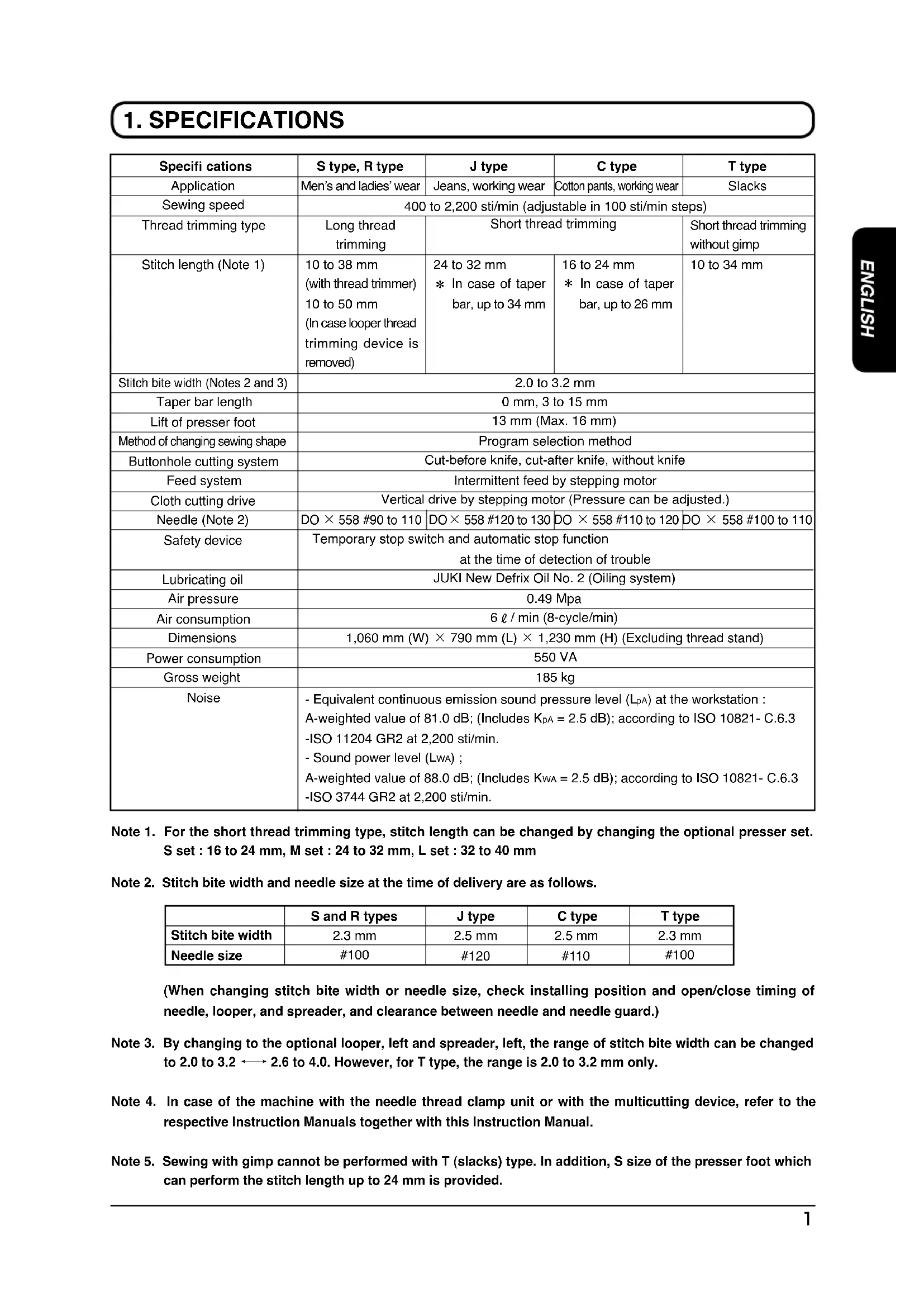
1. SPECIFICATIONS
| Specifi cations | S type, R type | J type | C type | T type |
| Application | Men's and ladies' wear | Jeans, working wear | Cotton pants, working wear | Slacks |
| Sewing speed | 400 to 2,200 sti/min (adjustable in 100 sti/min steps) | |||
| Thread trimming type | Long thread trimming | Short thread trimming | Short thread trimming without gimp | |
| Stitch length (Note 1) | 10 to 38 mm(with thread trimmer)10 to 50 mm(In case looper thread trimming device is removed) | 24 to 32 mm* In case of taper bar, up to 34 mm | 16 to 24 mm* In case of taper bar, up to 26 mm | 10 to 34 mm |
| Stitch bite width (Notes 2 and 3) | 2.0 to 3.2 mm | |||
| Taper bar length | 0 mm, 3 to 15 mm | |||
| Lift of presser foot | 13 mm (Max. 16 mm) | |||
| Method of changing sewing shape | Program selection method | |||
| Buttonhole cutting system | Cut-before knife, cut-after knife, without knife | |||
| Feed system | Intermittent feed by stepping motor | |||
| Cloth cutting drive | Vertical drive by stepping motor (Pressure can be adjusted.) | |||
| Needle (Note 2) | DO × 558 #90 to 110 | DO × 558 #120 to 130 | DO × 558 #110 to 120 | DO × 558 #100 to 110 |
| Safety device | Temporary stop switch and automatic stop functionat the time of detection of trouble | |||
| Lubricating oil | JUKI New Defrix Oil No. 2 (Oiling system) | |||
| Air pressure | 0.49 Mpa | |||
| Air consumption | 6 l / min (8-cycle/min) | |||
| Dimensions | 1,060 mm (W) × 790 mm (L) × 1,230 mm (H) (Excluding thread stand) | |||
| Power consumption | 550 VA | |||
| Gross weight | 185 kg | |||
| Noise | - Equivalent continuous emission sound pressure level (LpA) at the workstation:A-weighted value of 81.0 dB; (Includes KpA = 2.5 dB); according to ISO 10821-C.6.3-ISO 11204 GR2 at 2,200 sti/min.- Sound power level (LwA) ;A-weighted value of 88.0 dB; (Includes KwA = 2.5 dB); according to ISO 10821-C.6.3-ISO 3744 GR2 at 2,200 sti/min. | |||
Note 1. For the short thread trimming type, stitch length can be changed by changing the optional presser set. S set : 16 to 24 mm, M set : 24 to 32 mm, L set : 32 to 40 mm
Note 2. Stitch bite width and needle size at the time of delivery are as follows.
| S and R types | J type | C type | T type | |
| Stitch bite width | 2.3 mm | 2.5 mm | 2.5 mm | 2.3 mm |
| Needle size | #100 | #120 | #110 | #100 |
(When changing stitch bite width or needle size, check installing position and open/close timing of needle, looper, and spreader, and clearance between needle and needle guard.)
Note 3. By changing to the optional looper, left and spreader, left, the range of stitch bite width can be changed to 2.0 to 3.2 2.6 to 4.0. However, for T type, the range is 2.0 to 3.2 mm only.
Note 4. In case of the machine with the needle thread clamp unit or with the multicutting device, refer to the respective Instruction Manuals together with this Instruction Manual.
Note 5. Sewing with gimp cannot be performed with T (slacks) type. In addition, S size of the presser foot which can perform the stitch length up to 24 mm is provided.
2. NAME OF EACH COMPONENT
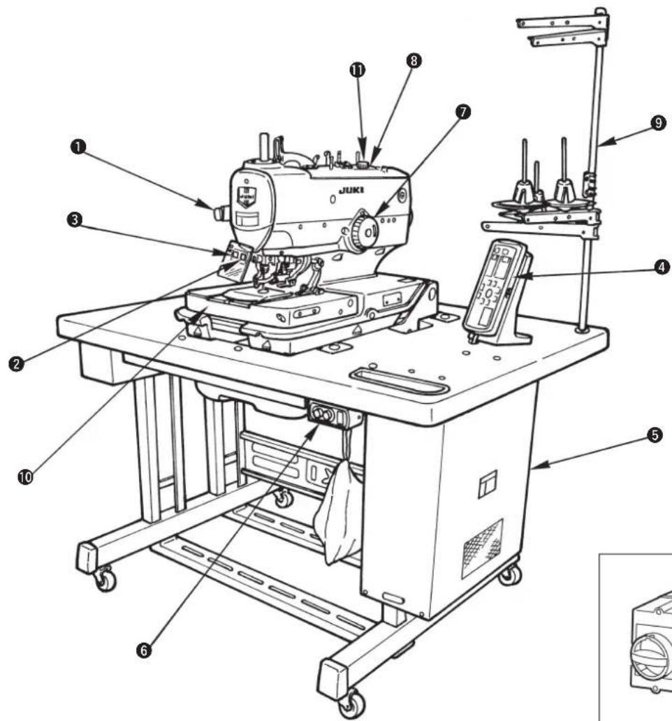
(1) Names of the sewing machine main unit
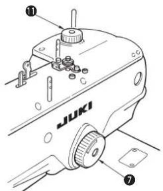
- Hand pulley ⑦
The needle bar can be lifted or lowered by hand with the handpulley
- Cloth cutting dial 11
The cloth cutting knife can be lifted or lowered by hand with the cloth cutting dial. (When the power is turned OFF.)

Hand pulley ⑦ and cloth cutting knife ⑪ rotate in accordance with the rotation of the sewing machine and the drive of the cloth cutting knife.
Be careful not to allow your hands or the like to touch to them during operation of the sewing machine.
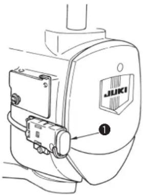
natural_image
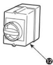
Technical line drawing of a mechanical component with a circular housing and an arrow pointing to a numbered label (12), no text or symbols present.① Temporary stop switch
② Presser switch
③ Start switch
4 Operation panel
5 Control box
6 Power switch
⑦ Hand pulley
8 Machine head
9 Thread stand
10 Feed base
⑪ Cloth cutting dial
⑫ Power switch (EU type)
3. INSTALLATION
(1) Installing the air hose
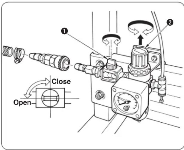
■ Connecting the air hose
Connect the air hose to the regulator using the hose band and the one-touch socket joint supplied with the machine.
■ Adjustment of air pressure
Open air cock ①, pull up and turn air adjustment knob ② and adjust so that air pressure indicates 0.45 to 0.55 MPa. Then lower the knob and fix it.
* Close air cock ① to expel air.
(2) Raising and returning the sewing machine

DANGER :
- If you find the sewing machine is too heavy to lift, the gas spring may have malfunctioned due to outgassing.
Never lift the sewing machine in such a state since the machine can drop to pinch hands, fingers and arms resulting in serious injury.
* Be sure to fully understand the standard of replacing time of the gas spring on p.56 and its replacement procedure on p.57 before putting the sewing machine into operation.
- In order to prevent pinching of hands, fingers and arms that can result in a serious injury, be sure to strictly observe the following when carrying out work.
2-1. Be sure to hold the rib on the bed periphery when holding the sewing machine.
2-2. Be sure to lock the hinge stopper to firmly secure the sewing machine in its raised position.
Fixing screw, left
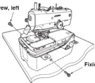
Fixing screw, right
1) Remove the fixing screws, right and left for transportation.
(8 mm wrench is supplied with the machine.)

Retain the screws since they are necessary when moving the sewing machine. Be sure to attach them when moving the sewing machine.
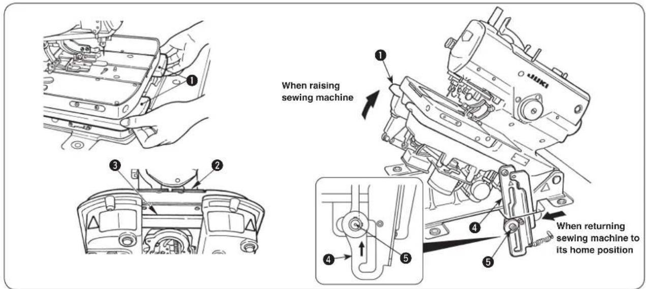
2) When raising the sewing machine, push feed base ② away from you (in the direction of the arrow), then hold periphery ribs ① located on the front side of the sewing machine bed to slowly lift it.
At this time, do not hold feed base ② and feed guide shaft fixing base ③.

DANGER :
- Do not hold any part other than periphery ribs ① of machine head.
- Confirm that hinge stopper ④ is locked with support shaft ⑤.
CAUTION :
If you raise the sewing machine from its home position with the feed base remained near side, the feed base can move to pinch hands and fingers leading to an unexpected injury.
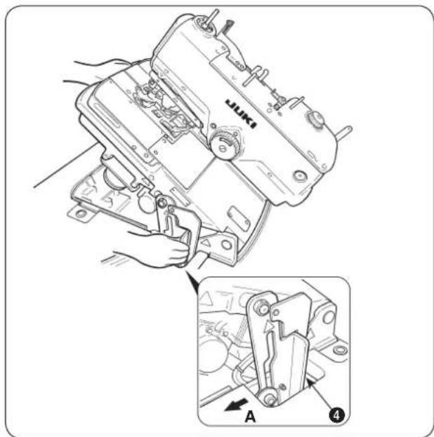
3) When returning the sewing machine, support periphery ribs ① of the machine bed with your left hand, hold grip ④ of the hinge stopper section with your right hand, pull it to this side (direction A) to release the lock and slowly lower the sewing machine after confirming that there is no tool such as screwdriver and the like in the bottom cover.
natural_image
Line drawing of a sewing machine with hands operating it (no text or symbols)4) Take your right hand off from the hinge stopper section, support periphery ribs ① of machine bed with your both hands, and further lower the sewing machine.
DANGER :
- Do not lower the sewing machine while

keeping pulling the hinge stopper in direction A, in order to prevent pining of fingers, hands and arms under the sewing machine leading to a serious injury.
- Do not hold feed base ② and feed guide shaft fixing base ③.
natural_image
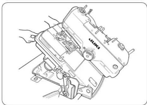
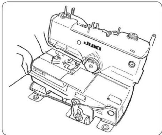
Line drawing of a sewing machine with hands operating it (no text or symbols)5) The sewing machine stops once more at the final stage of lowering for the safety. Support the periphery ribs of machine bed with your left hand, hold the grip of hinge stopper section with your right hand to release the lock and slowly lower the sewing machine following the description of step 3).
DANGER :

Take care to prevent pinching of hands and fingers between the sewing machine and the bottom cover. In particular, never lower the sewing machine holding parts other than the bed rib with two or more workers, since doing so can cause pinching of hands, fingers and arms leading to a serious injury.
(3) Installing the thread stand
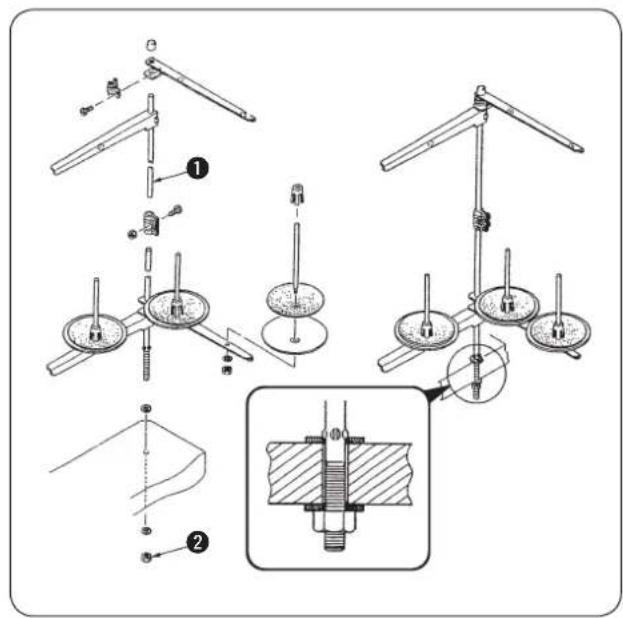
1) Assemble thread stand unit ②. 2) Insert it in the hole located in the rear of the machine table, and tighten locknut ① to fix the thread stand.

When the ceiling wiring is possible, pass the power cord through the spool rest rod.
(4) Installing the operation panel base
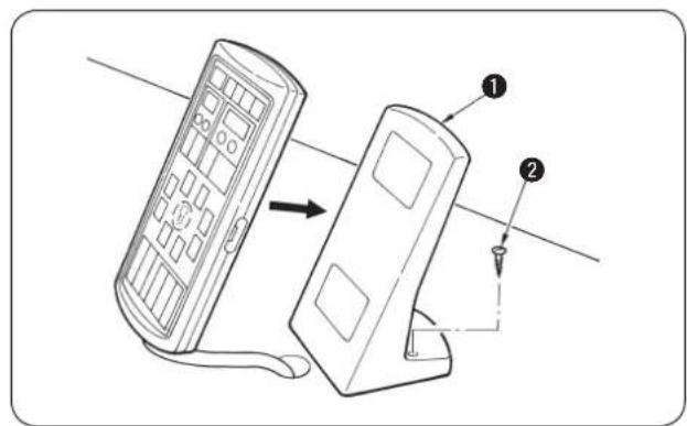
Fix operation panel base ① at the dotting punch section on the machine table with wood screw ②.

Protection vinyl is coated on the surface of the operation panel. Remove it.
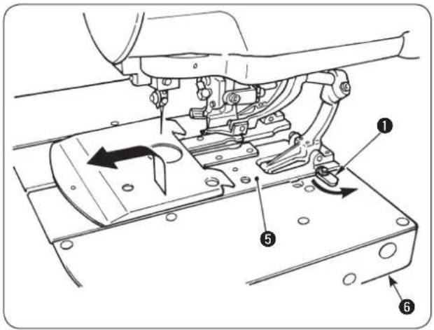
(5) Installing/removing the presser unit
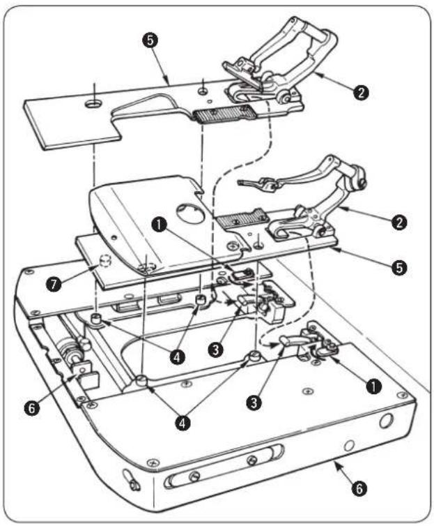

When moving the feed base by hand, or removing/attaching the presser unit, be careful so that the cloth cutting knife does not come in contact with the holding plates, or the thread trimming unit does not come in contact with the throat plate.
How to install
1) Install the presser unit so that presser lever ③ fits in the letter "U" of presser base ②.
2) Adjust the hole of presser plate ⑤ to cloth open pin ④.
3) Turn clamp holding plate ① to hold presser plate ⑤.

When installing the presser unit ⑤, insert correctly thread trimming driving arm roller ⑦ into the concave in looper thread trimming cylinder click ⑥. If the roller is off, the looper thread trimming unit interferes with the throat plate during sewing. As a result, component breakage will be caused.
How to remove
1) Turn clamp holding plate ① to remove from presser plate ⑤.
2) Lifting presser plate ⑤, remove it so as to draw it.

It is comparatively easy to install or remove the presser unit by moving feed base ⑥ to the cloth cutting position. ([THREAD] key is convenient. P.18) When moving feed base ⑥ by hand, follow the aforementioned caution.
(6) Attaching the dust bag
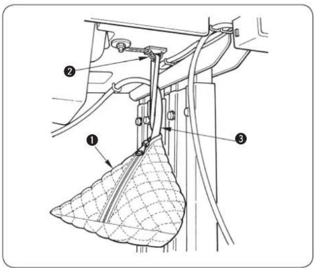
Attach dust bag ① to clamp ② located in the rear face of the table and insert dust hose ③ into the bag.
4. PREPARATION BEFORE OPERATION
(1) Lubricating the machine and how to lubricate

WARNING : Turn OFF the power before starting the work so as to prevent accidents caused by abrupt start of the sewing machine.
* Use JUKI New Defrix Oil No. 2.
Lubricating the arm oil tank
Lubricate arm tank ① to such an extent of approximately 80 %.
Lubricating the bed oil tank

DANGER : Be sure carry out the work while observing the following in order to protect against pinching of hands, fingers and arms between the sewing machine and the bottom cover, which can result in serious injury, when you raise the sewing machine from its home position.
- Be sure to lock the hinge stopper to firmly secure the sewing machine in its raised position.
* Read and check how to rise/return the sewing machine described on p.3 to p.5.
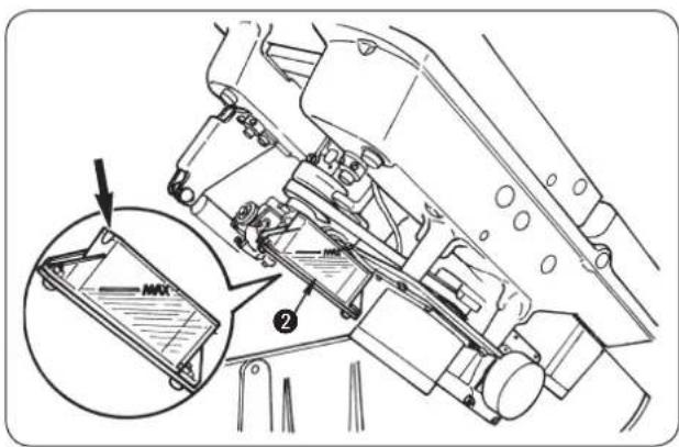
1) Raise the machine head.
2) Lubricate bed oil tank ② up to the MAX. line.
3) Return the machine head to its home position.
■ Lubricating the looper and spreader components

DANGER :
Be sure carry out the work while observing the following in order to protect against pinching of hands, fingers and arms between the sewing machine and the bottom cover, which can result in serious injury, when you raise the sewing machine from its home position.
- Be sure to lock the hinge stopper to firmly secure the sewing machine in its raised position.
* Read and check how to rise/return the sewing machine described on p.3 to p.5.
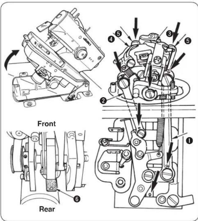
1) Remove the presser plates, left and right, and raise the machine head.
2) Apply two to three drops of oil to looper link ①, spreader link ②, spreader, right ③, spreader, left ④ and spreader actuating cam ⑤.

- Be sure to lubricate the components once a day. If the frequency of lubrication is small, especially, worn-out of ③, ④ and ⑤ is caused and stitch skipping or needle breakage will occur.
- Apply oil to the oil wicks and the felts (looper cam oiling felt ⑥ or the like) in the machine bed at the time of delivery or after an extended period of disuse.
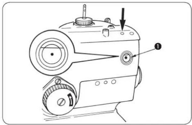
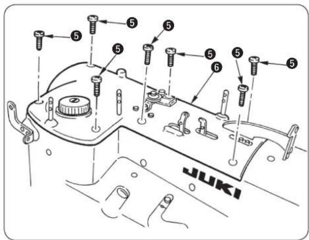
■ Lubricating the needle bar and cam components

Lubricate the components at the time of delivery or after an extended period of disuse.
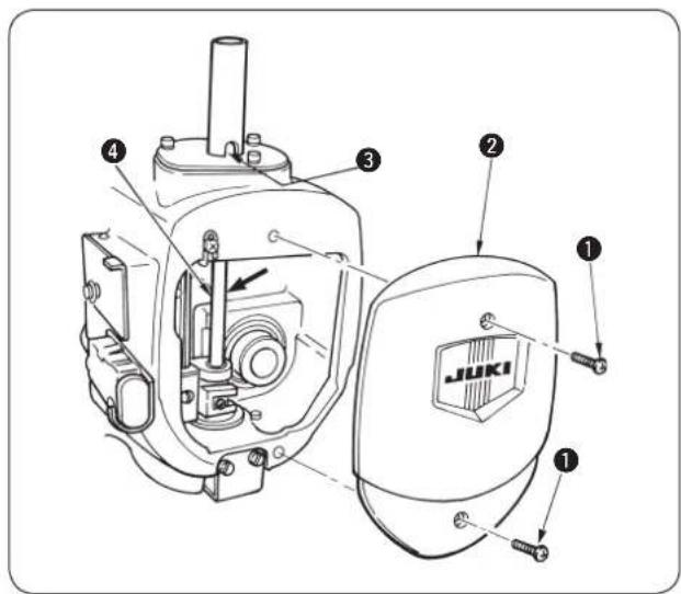
1) Loosen setscrews ① and remove face plate ②.
2) Apply one to two drops of oil to needle bar bushing ③ and needle bar ④.
3) Apply oil to the felts and the oil wicks in the face plate section of the sewing machine.
4) Loosen setscrew ⑤ and remove the upper face cover ⑥.

Remove the cover with care since the air tube is connected with the cord.
5) Apply oil to the felts and the oil wicks in the sewing machine arm.
6) After lubrication, install face plate ② and upper face cover ⑥.

Be careful not to allow the cords to be caught in the machine.
(2) Attaching the needle

WARNING :
Turn OFF the power before starting the work so as to prevent accidents caused by abrupt start of the sewing machine.
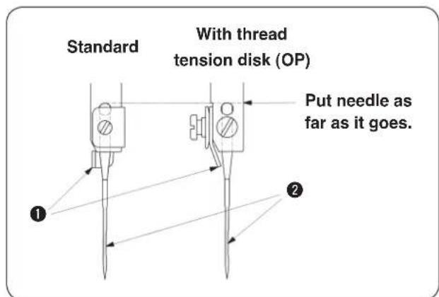
TThe correct direction of the needle is that needle thread guide ① faces the opposite side of groove ② of the needle.

- Use the most suitable size of needle in accordance with the kind and thickness of thread and kind of material to be used.
- When changing the size of needle, be sure to adjust the clearance between the needle and the looper. (Refer to (3) Clearance between the needle and the looper, p.47.)
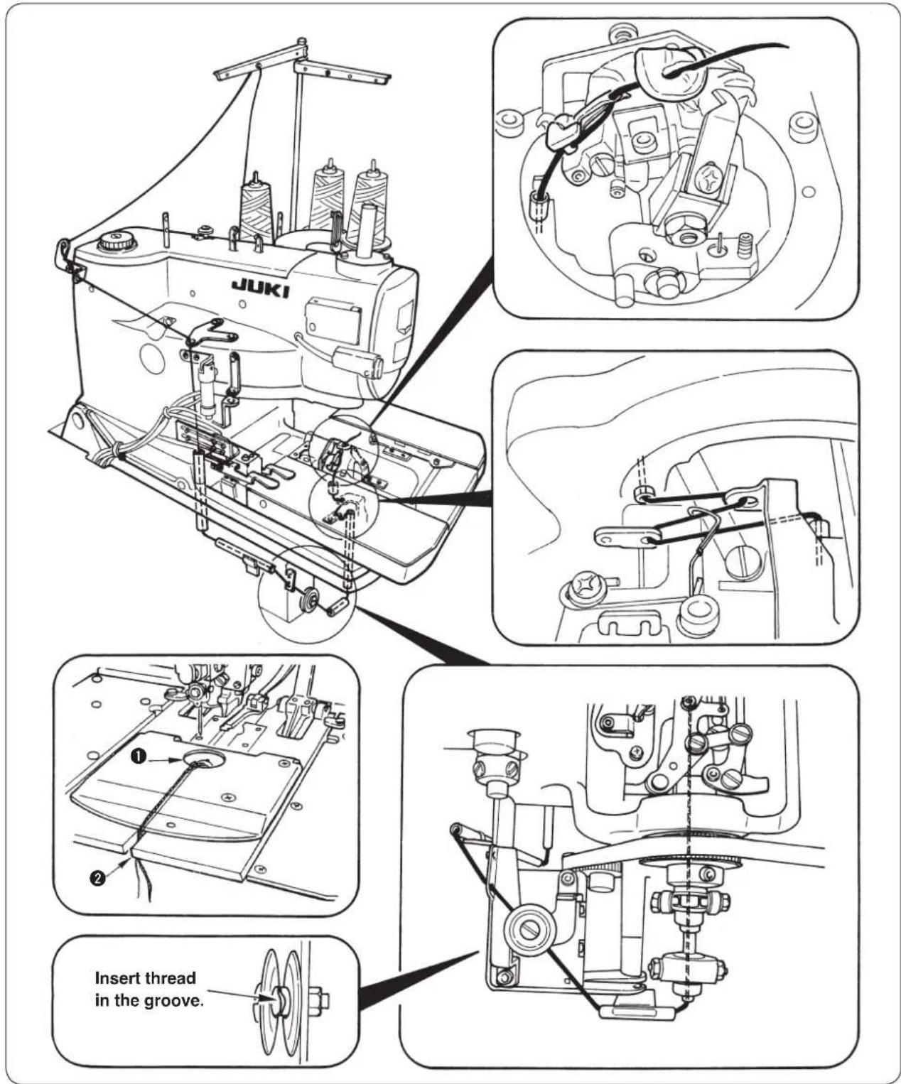
(3) Threading the machine head

WARNING :
Turn OFF the power before starting the work so as to prevent accidents caused by abrupt start of the sewing machine.
Threading the upper thread (needle thread)
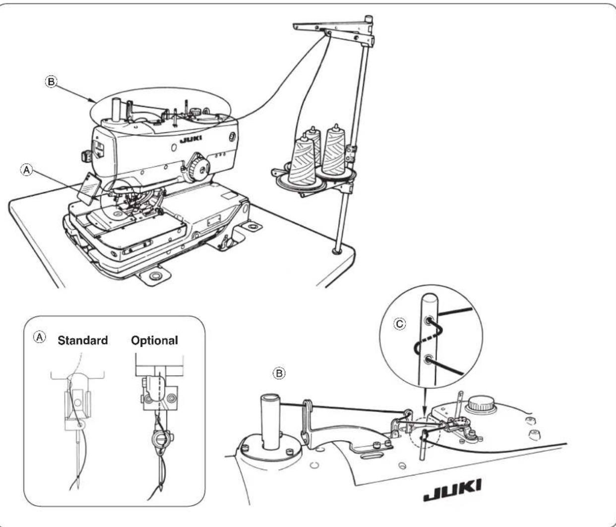
Threading the lower thread (looper thread)

DANGER :
- If you find the sewing machine is too heavy to lift, the gas spring may have malfunctioned due to outgassing.
Never lift the sewing machine in such a state since the machine can drop to pinch hands, fingers and arms resulting in serious injury.
* Be sure to fully understand the standard of replacing time of the gas spring on p.56 and its replacement procedure on p.57 before putting the sewing machine into operation. - In order to prevent pinching of hands, fingers and arms that can result in a serious injury, be sure to strictly observe the following when carrying out work.
2-1. Be sure to hold the rib on the bed periphery when holding the sewing machine.
2-2. Be sure to lock the hinge stopper to firmly secure the sewing machine in its raised position.

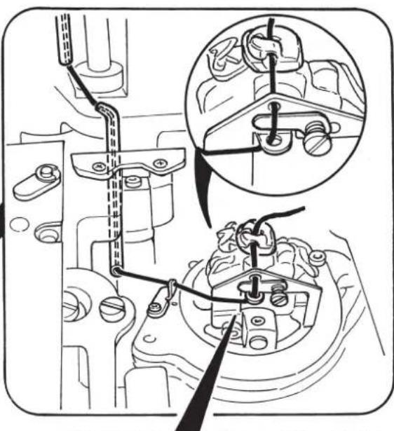
- When passing the looper thread, turn the looper bracket by 180^ and pass it.
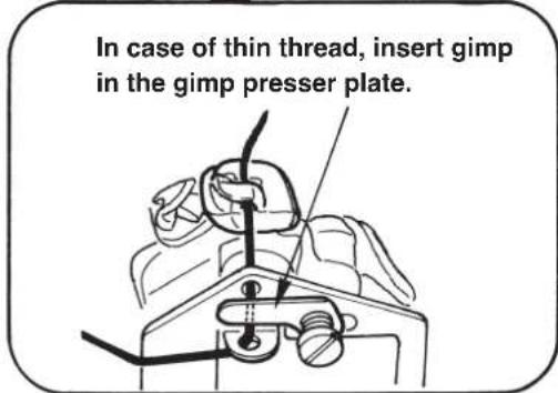
- Pass the looper thread and gimp through the needle hole in the throat plate and pull them out from hole ①. Then clamp them at ② of the presser plate and perform a few stitch sewing to remove the looper thread and gimp (2 pcs.). When the sewing is completed, the looper thread is retained with the looper thread clamp and gimp with the gimp clamp. If thread waste is clamped, remove it since clamping becomes incomplete and stitch skipping at the sewing start will be caused.
[Refer to the item “(9) Adjusting the looper thread trimming” on page 53.] - In case of T type, when performing sewing immediately after threading, place backward the looper thread through the needle hole in the throat plate and perform partial sewing, or retain the looper thread on the looper thread presser and perform sewing. [Refer to the item “(9) Adjusting the looper thread trimming” on page 53.]
Threading the machine with gimp
* T type is without gimp.
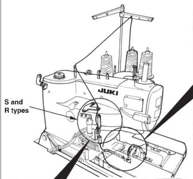
natural_image
Technical diagram of engine components with mechanical assembly and close-up insets (no text or labels)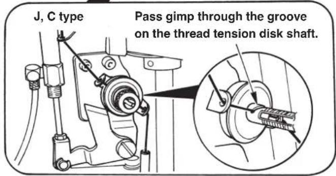
(4) How to set the cloth

* S type : 13.5 to 30 mm
* J, C and T types : 10.0 to 26 mm
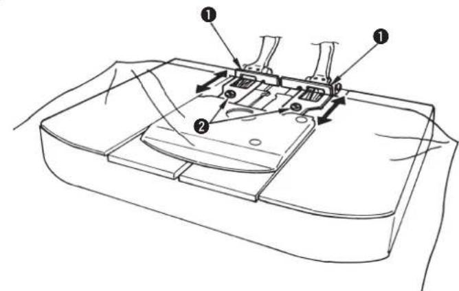
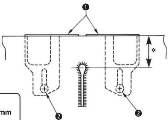
1) Enter the sewing material until it comes in contact with cloth patches ①, right and left.
2) Loosen setscrews②, right and left and adjust the sewing position by moving the cloth patches to and fro.
5. STRUCTURE OF THE OPERATION SWITCH
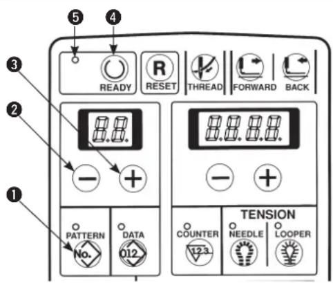
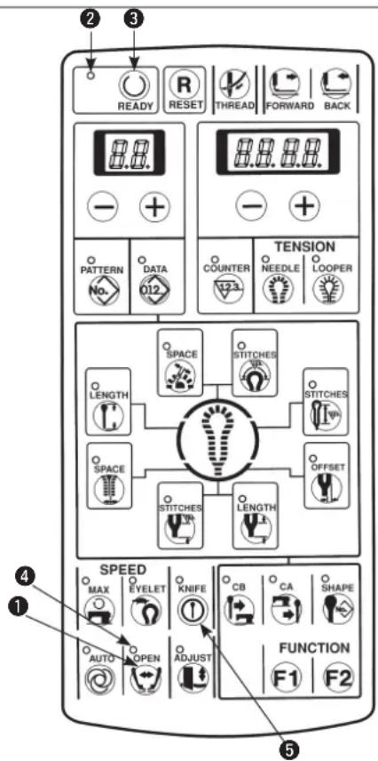
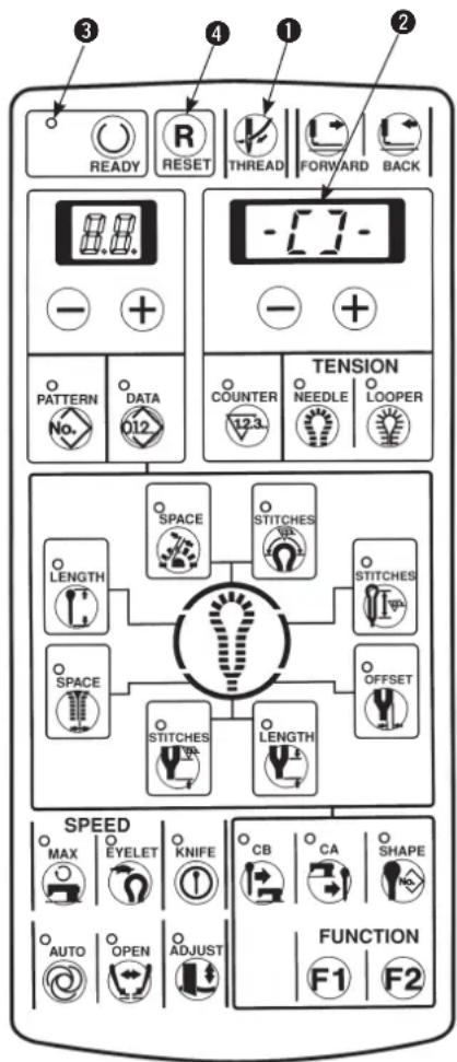
(1) Structure of the operation panel
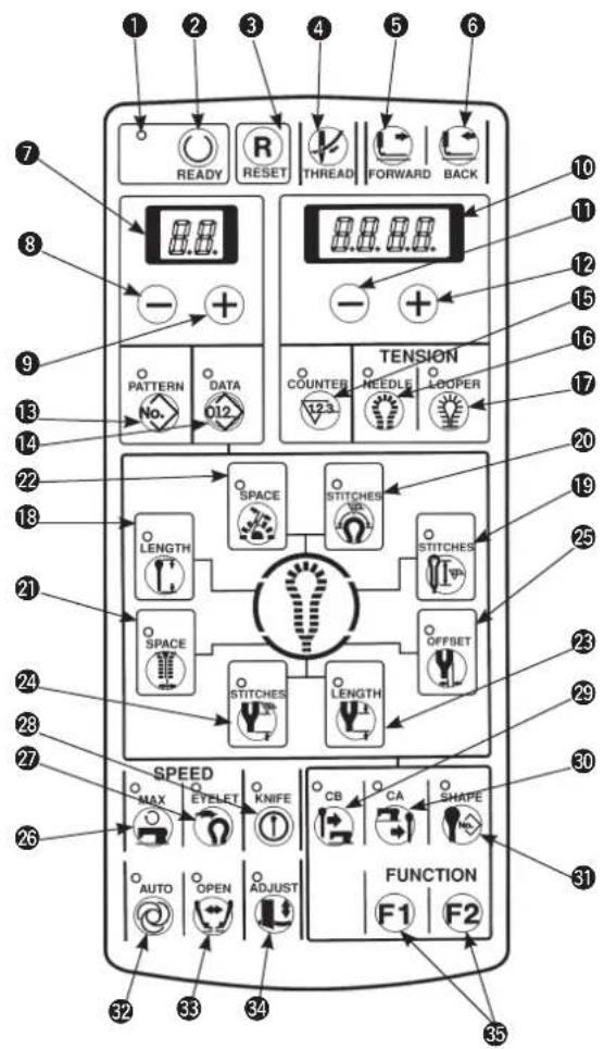
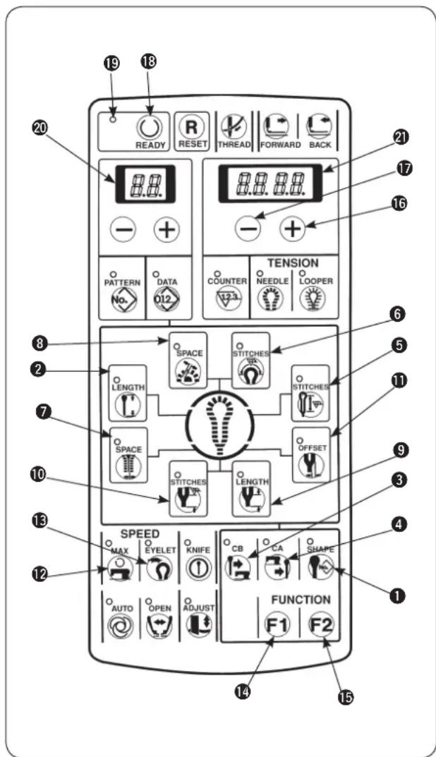
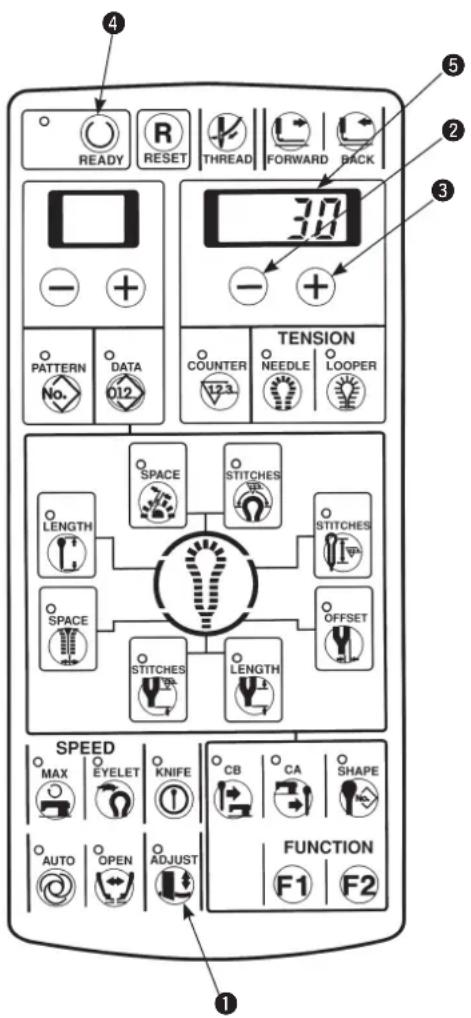
[Table of functions of the operation panel]
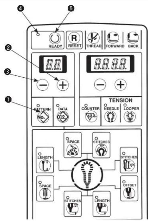
| No. | Name | Descr iption | No. | Name | Description | |
| 1 | Sewing LED | This LED lights up when the sewing machine can be operated. | 6 | BACK key | When this key is pressed, the feed mechanism travels backward stitch by stitch. | |
| 2 | READY key | Setting ⇔ sewing ready can be changed over alternately every time this key is pressed. | 7 | 2-digit LED | This LED displays pattern No. normally and data No. at the time of data setting. | |
| 3 | RESET key | Error release (at the time of various errors)• Reset of the production counter• Move of the feed setting position Release of the threading mode | 8 | LEFT “-” key  | This key subtracts pattern No. or data No. | |
| 4 | THREAD key | Mode becomes the threading mode (P.18) when this key is pressed.(When the sewing LED lights up.) | 9 | LEFT “+” key  | This key adds pattern No. or data No. | |
| 5 | FORWARD key | When this key is pressed, the feed mechanism travels forward stitch by stitch. | 10 | 4-digit LED | This LED displays cut length, contents of data setting, counter value, error No., etc. | |
| NO. | Name | Description | NO. | Name | Description | |
| 11 | RIGHT “-” key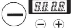 | This key subtracts various data. | 23 | LENGTH (Taper bar length) keyNote 1 |  | This key sets sewing length of taper bar.Note 1 |
| 12 | RIGHT “+” key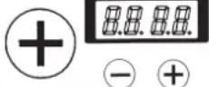 | This key adds various data. | 24 | STITCHES (Number of stitches of taper bar)key |  | This key sets the number of stitches of taper bar.Note 1 |
| 13 | PATTERN key | This key performs display and setting of pattern No. | 25 | OFFSET(Taper bar offset) key |  | This key sets the slip amount of taper bar.Note 1 |
| 14 | DATA key | This key performs display and setting of data No. | 26 | MAX(Sewing speed) key |  | This key performs setting of sewing speed.Note 1 |
| 15 | COUNTER key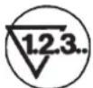 | This key performs display of counter. | 27 | EYELET(Eyelet speed setting) key |  | This key performs setting of reduced speed at eyelet section.Note 1 |
| 16 | NEEDLE key | This key performs display and setting of needle thread tension data. | 28 | KNIFE(Knife ON/OFF)key |  | This key sets effective/ineffective of knife.Note 3 |
| 17 | LOOPER key | This key performs display and setting of loop thread tension data. | 29 | CB(Before-cut knife) key |  | This key performs data setting of before-cut knife.Note 2 |
| 18 | LENGTH key | This key sets the length to be sewn.Note 1 | 30 | CA(After-cut knife) key |  | This key performs data setting of after-cut knife.Note 2 |
| 19 | STITCHES(Number of stitches of parallel)key | This key sets the number of stitches of the parallel section.Note 1 | 31 | SHAPE(Knife No.)key |  | This key selects the No. of kind of knife to be used.Note 1 |
| 20 | STITCHES(Number of stitches of eyelet)key | This key sets the number of stitches of the eyelet section.Note 1 | 32 | AUTO(Auto operation)key |  | This key performs change-over of automatic and manual operation modes. |
| 21 | SPACE(Cut space)key | This key sets clearance between cloth cutting knife and sewing at the parallel section. Note 1 | 33 | OPEN(Cloth open) key |  | The mode becomes the one operating with the cloth open mechanism opened. |
| 22 | SPACE (Eyelet space) key | This key sets clearance between cloth cutting knife and sewing at the eyelet section. | 34 | ADJUST(Knife adjust)key | The mode becomes the one of cloth cutting knife adjustment by turning ON the power with this key held pressed. | |
| 35 | FUNCTION(Function) key |  | This key can be changed to optional data setting function key with the memory switch.At the time of deliveryF1: Knife position adjustment (No. 8)F2: Copy destination No. (No. 80) | |||
Note 1 : When changing the set value, operate the panel in the state that the sewing LED has gone out.
Note 2 : When both the before-cut and after-cut knives are not selected (set value: "0"), the data without knife is selected.
Note 3 : Effective / ineffective of knife operation can be selected in case of the before-cut and after-cut knives, however, in case of the data without knife, the knife operation cannot be performed.
(2) Temporary stop switch
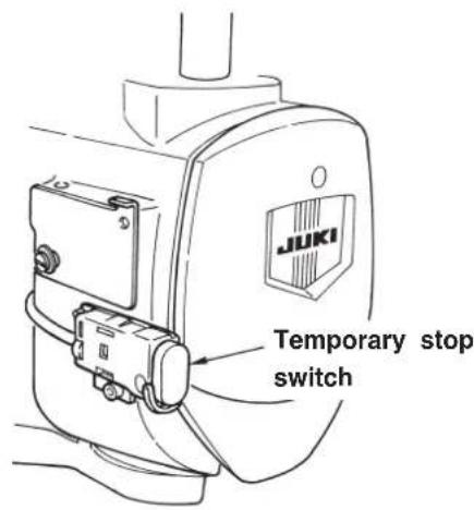
This switch stops the operation of the sewing machine.
(3) Hand switch
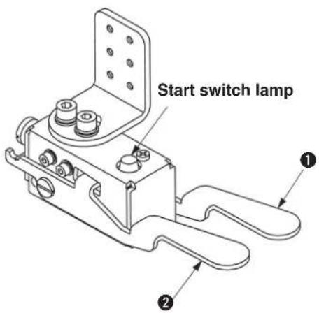
Presser switch (right) ①
This switch performs up/down of the presser.
Start switch (left) ②
This switch performs the start of sewing.

When the start switch is effective, the start switch lamp flashes on and off.

This switch is provided as standard.
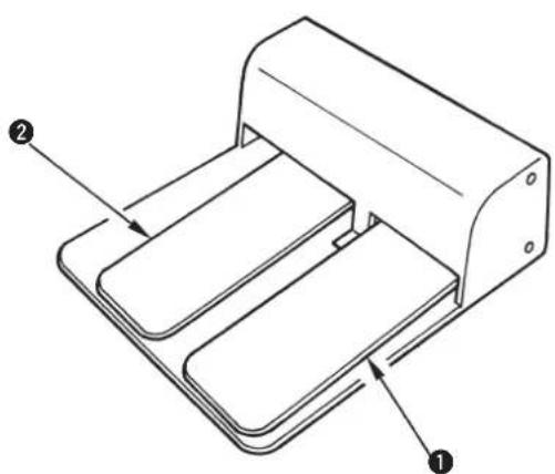
(4) Foot switch
natural_image
Technical line drawing of a mechanical device with labeled components (no text or symbols present)Presser switch ①
This switch performs up/down of the presser.
Start switch ②
This switch performs the start of sewing.

This switch is optional.
- For J and C type, the pattern No. which is different in the presser type cannot be used.
The standard patterns which can be used with the respective presser types are as shown below.
(See page 70 for the standard patterns.).
- For T type, No. 90 to 96 for S and M types can be used.
| S type | C type at the time of delivery | No.90, No.91, No.92 |
| M type | J type at the time of delivery | No.93, No.94, No.95, No.96 |
| L type | No.97, No.98, No.99 |
(1) Basic operation of the sewing machine
1) Set the display to pattern No. with [PATTERNNo.] key ①.
2) Press [LEFT ☐] key ② or [LEFT ⨁] key ③ to select the pattern desired to be sewn.
3) Press [READY Ⓞ] key ④ to light up sewing LED ⑤ and to make it possible to sew. At this time, feed base, knife and needle bar perform the origin retrieval.
4) Set the sewing material to the presser section, and lower the presser using the presser switch. Press the start switch and the sewing machine starts sewing.
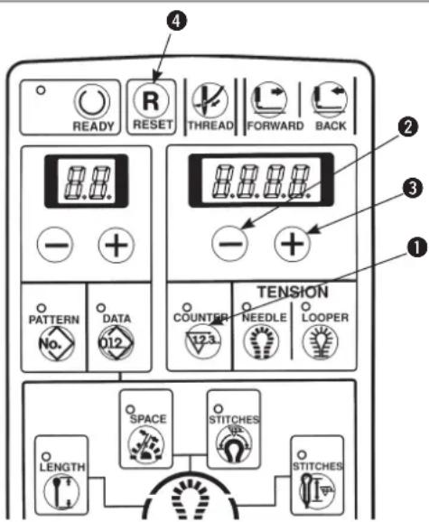
(2) Setting the thread tension

The actual thread tension varies in accordance with the kind or thickness of thread used even when the set value is the same. Adjust the thread tension value to the thread used. If the thread tension set value is high, stitch skipping may be caused.
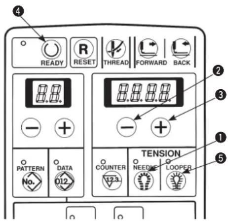
■ Setting of the needle thread tension
1) Press [NEEDLE] key ① to display the needle thread tension value.
2) Press [RIGHT⊕] key③ or [RIGHT⊖] key② to change the set value.

When pressing [RIGHT+] key to increase the numeric, the needle thread tension is increased.
When pressing [RIGHT] key to decrease the numeric, the needle thread tension is decreased.
3) Press [READY Ⓞ] key ④ or when starting sewing with the start switch, the set value is stored in memory.
■ Setting of the looper thread tension
1) Press [LOOPER] key 5 to display the looper thread tension value.
2) Press [RIGHT⊕] key ③ or [RIGHT—] key ② to change the set value.

When pressing [RIGHT ⊕] key ③ to increase the numeric, the thread tension is increased.
When pressing [RIGHT ⏻] key ② to decrease the numeric, the thread tension is decreased.
3) Press [READY] key4 or when starting sewing with the start switch, the set value is stored in memory.

When the pattern No. is changed without performing the operation of step 3) or turning OFF the power, the set value is not stored in memory.
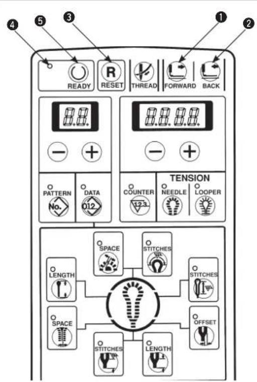
(3) Temporarily stopping the sewing machine
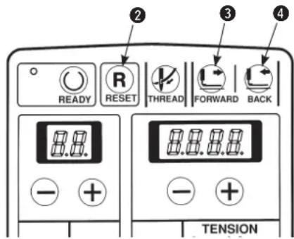
■ How to stop the sewing machine
1) Press temporary stop switch ①.
2) The sewing machine stops and "Er 10" is displayed.
How to re-start
1) Press [RESET Ⓡ] key ② while “Er 10” is being displayed and the error is released.
2) Re-start the sewing machine using the start switch, or press [FORWARD ] key ③ or [BACK ] key ④ and the feed mechanism travels forward/ backward stitch by stitch.
Further, press [RESET R] key ① to return the sewing machine to the sewing start position.

Operation of [FORWARD] key, [BACK] key or [RESET] key cannot perform thread trimming.

When temporarily stopping the sewing machine during sewing and returning the sewing machine to the start position with [RESET R] key, draw out needle thread, cut the thread with scissors or the like and perform the work. The work can be performed without applying a forced load to needle or sewing product.
(4) Performing re-sewing
Sewing can be performed without making the cloth open operation.
1) Make sure that sewing LED ② goes out.
When the LED lights up, press [READY ①key ③ to make it go out.
2) Press [OPEN 📋] key ① to light up cloth open LED ④.
3) Press [READY Ⓞ] key ③ to perform the origin retrieval and the right and left presser plates open. The cloth setting position becomes the knife actuating position.
4) The sewing can be performed with the presser switch and the start switch. Cloth open ON/OFF operation is not performed.
5) To release this setting, press [READY Ⓞ] key ③ to make the sewing LED go out, then press [OPEN ⬇] key ① to make cloth open LED ⑤ go out.

When the cloth cutting knife is not operated, prohibit the knife operation with [KNIFE ON/OFF ①] key ⑤.
(5) Performing threading

WARNING :
Turn OFF the power after operation of steps 1) and 2), and replace needle, thread, cloth cutting knife or knife holder.
1) Press [THREAD ⏻] key ① when sewing LED ③ lights up and the sewing machine stops at the setting position.
① The needle bar rotates by 180^ and threading can be performed from the front side.
② The presser comes down.
③ Change the cloth set position (memory switch No.11=1), and the presser (feed base) moves to the rear (origin position) when the front set is used.
④ The cloth cutting drive motor is turned to OFF, and the cloth cutting dial can be turned by hand.
⑤ Display is shown as -[] - 2.

In this state, keys other than [THREAD
key ① and [RESET Ⓡ] key④ cannot be accepted.

2) Press again [THREAD ⏻] key ① and the needle bar only returns to its home position.
3) Press [RESET R] key ④ and ① to ⑤ return to their home positions.

The presser and the feed base operate.
Be careful that hands or fingers are not being caught in them.

It is recommended to perform installing/removing the presser unit after operating the aforementioned step 1) and turning OFF the power.
(6) How to use the counter

The counter has been set to UP counter in
the state of delivery.
1) Press [COUNTER 123] key① to display the counter value.
2) Every time the sewing machine completes one cycle stitching, the value increases by 1 count.
3) The counter value can be changed with [RIGHT
— ] key ② or [RIGHT +] key ③.
4) Press [RESET R] key ④ to return the counter value to "0".

The counter can be used as DOWN counter as well.
(Refer to the item "10. Various functions : (6)
Change-over of the counter" P.43.)
(7) When dropping of the knife is temporarily not desired
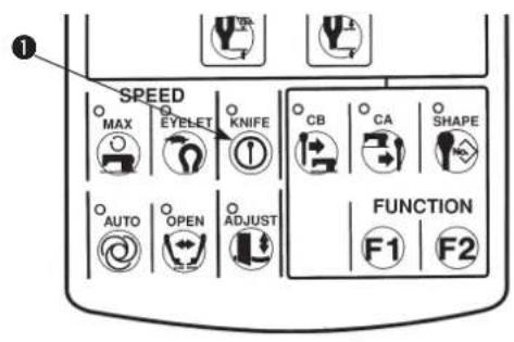
1) Press [KNIFE ①] key to make the LED go out. The knife does not work when the LED goes out.
2) Press [KNIFE Ⓤ] key ① again to make the LED light up and the knife can be operated.
(8) Changing the operation mode
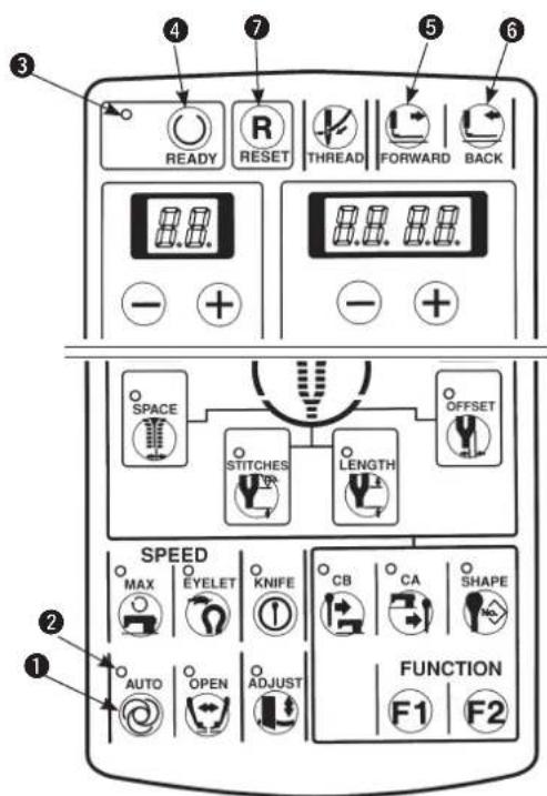

- When sewing LED ③ goes out, press [AUTO 🔒] key ① to change the operation mode.
• The machine works in [MANUAL mode] when the AUTO LED ② goes out, and in [AUTO mode] when the AUTO LED lights up.
[AUTO mode]
Lower the presser foot, press the start switch, and a sequence of operation such as drive of cloth cutting knife, sewing, thread trimming, etc. is performed. This is the normal sewing mode.
[MANUAL mode]
This operation mode is an operating procedure to turn the handwheel by hand without rotating the sewing machine so that a step operation which makes the feed base travel stitch by stitch is performed. In addition, the knife operation, and the thread trimming operation can be performed step by step.
1) Make sure that sewing LED ③ has gone out. When it lights up, press [READY ①key ④ to make it go out.
2) Press [AUTO] key to make AUTO LED go out.
3) Press [READY Ⓞ] key ④ to light up sewing LED ③ and to make the sewing possible.
4) Lower the presser with the presser switch.
5) Press the start switch. When the cut-before knife is used, and the position of the feed base is not in the position of the knife, the feed base moves to that of the knife.
6) Press the start switch. When the cut-before knife is used, the cloth cutting knife works.
7) Press the start switch. The cloth open mechanism is opened.
8) Press the start switch. The feed base travels to the sewing start position and the buzzer beeps.
9) Turn the handwheel in the direction of the arrow mark. The feed base interlocking with the needle position travels stitch by stitch.
Turn the handwheel and when the feed base comes to the sewing end position, the buzzer beeps.
10) It is possible to make the feed base only travel up to the sewing end position using [FORWARD] key ⑤ or [BACK] key ⑥.
11) Every time the start switch is pressed, the feed base travels and needle thread trimming operation or looper thread trimming operation is performed step by step. When the after-cut knife is used, the cloth cutting knife operation is performed step by step.
12) When temporarily stopping the change, press [RESET R] key ⑦ and the feed base returns to the set position.
![JUKI MEB3200 - [MANUAL mode] - 1](/content/2026/04/604076/images/14634c5d4285ac8a665e355c3f5015adaae1f5435d5bdcf2d74ed79dd7d80d54.jpg)
Be sure to turn the handwheel in the normal direction since the feed mechanism does not perform the receding operation even when the handwheel is turned in the reverse direction.
(9) Changing procedure of the sewing pattern
1) Make sure that sewing LED ④ goes out.
(When the LED lights up, press [READY]⑤ key to make it go out.)
2) Press [PATTERNNo.] key ① to display the pattern No.
3) Press [LEFT +] key ② or [LEFT -] key ③ to select the pattern you desire to sew.
(The number of pattern which is not registered is not displayed.)
4) Press [READY] key ⑤ to light up sewing LED ④ and to make it possible to sew.
(10) Confirming the pattern shape
1) Press [READY] key ⑤ to light up sewing LED ④ and to make it possible to sew.
2) Lower the presser with the presser switch.
3) Every time [FORWARD] key ① or [BACK] key ② is pressed, the feed mechanism travels forward/backward stitch by stitch and continually moves up to the position of the sewing end. In addition, the feed mechanism continually travels when keeping the key held pressed.
4) After completing the confirmation of the sewing pattern, press [RESET ☐] key ③ to return the machine to its set position.

If the START switch is pressed during confirmation of the pattern shape, sewing starts from the position where the switch is pressed. So, be careful.
7. SETTING PROCEDURE OF THE SEWING DATA

The standard patterns of pattern Nos. 90 to 99 can change the sewing speed and the thread tension, however, cannot change the sewing shape. When changing the shape, it is necessary to copy the shape to another pattern No. [See item (20) Copy destination No. on page 38.]
1) Confirm that sewing LED 19 has gone out.
When it lights up, press [READY] key 18 to make it go out.
2) Display the pattern No. you desire to change the data.
3) Press the respective setting keys of the parts desired to be changed and display the data.
① [SHAPE] key
② [LENGTH ]key
③ [CB] key
4 [CA] key
⑤ [STITCHES ⑪] key
6 [STITCHES key
⑦ [SPACE] key
⑧ [SPACE 4] key
⑨ [LENGTH] key
10 [STITCHES] key
⑪ [OFFSET ⚫] key
⑫ [MAX 🔍] key
⑬ [EYELET] key
14 [FUNCTION F1 F1 key
15 [FUNCTION F2 F2 key
4) Press [RIGHT ⊕] key 16 or [RIGHT —] key 17 to set the respective data.
5) Press [READY] key 18 to light up sewing LED 19 and the data are stored in memory.

When changing the pattern No. without pressing [READY Ⓞ] key or turning OFF the power, the data are not stored in memory.
6) When the memory switch No. 20 is set to "1", change of data setting in the above step 4) can be prohibited. (See the item of the memory switch on page 68.)

The data No. is stated in 2-digit LED ⑳ and the example of the set value is stated in 4-digit LED ㉑ as shown below. The setting range is stated in the respective sentences.
(1) Setting the knife No.
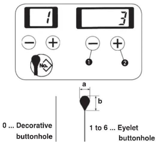

Set the knife No. of the same shape as that of the knife mounted on the sewing machine. [See item (1) on page 26.]
Set the knife No. with [RIGHT —] key ① or [RIGHT

The No. can be set 0 to 6.
| No. | a | × b |
| 1 | 2.1 | × 3.2 |
| 2 | 2.5 | × 3.8 |
| 3 | 2.9 | × 4.4 |
| 4 | 3.0 | × 4.6 |
| 5 | 3.2 | × 5.4 |
| 6 | 2.7 | × 5.1 |
(2) Setting the cut length
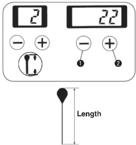

When the cut length is changed, the number of stitches of the parallel section will automatically change.

Set the length to be cut with the knife.
Set the length with [RIGHT] key① or [RIGHT] key②.
The length can be set in increments of 1 mm within the range of the table below in accordance with the thread trimming type. The figures in () parentheses are in case of taper bar or without bar tacking.
| Thread trimming type | Setting range |
| Long thread trimming | 10 to 38 mm |
| Long thread trimming without loop thread trimming | 10 to 50 mm |
| Short thread trimming : Sewing length S | 16 to 24 (26) mm |
| Short thread trimming : Sewing length M | 24 to 32 (34) mm |
| Short thread trimming : Sewing length L | 32 to 40 (42) mm |
| Short thread trimming without gimp (T) | 10 to 34 mm |

When sewing length is lengthened in case of taper bar length, compensation at the sewing end, etc., the setting range of the cut length is decreased as much as the length. Example) Cut length + (plus) taper bar length ≤ 38 mm (long thread trimming)
(3) Setting the cut-before/cut-after knives
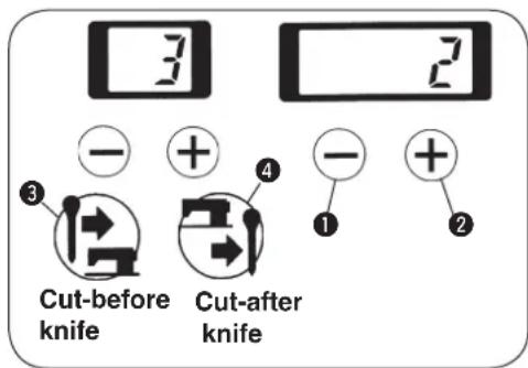

Set whether the cut-before knife or the cut-after knife.
1) Data of the cut-before knife can be immediately set with [CB] key③.
2) Data of the cut-after knife can be immediately set with [CA ④] key ④.
3) The data can be set with [RIGHT ]key ① or [RIGHT ⊕] key ② as well.
When setting the data without knife, set the value to "0".
Set value can be set "0" to 2.
| Set value | Motion |
| 0 Without knife | |
| 1 | Cut-before knife |
| 2 Cut-after knife | |
(4) Setting the number of stitches of the parallel section
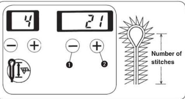

Set the number of stitches from the parallel section to the bottom section of eyelet.
Set the number of stitches with [RIGHT] key ① or [RIGHT] key ②.

- The number of stitches can be set to such an extent of 3 to 100 stitches. The number of stitches that can be set is limited by the set value of cut length.
Example) When the cut length is equal to 22 mm, the number of stitches is 6 to 41 stitches. In addition, if the number of stitches is decreased, the number of revolution of the sewing machine automatically reduces. - For T type, looper thread can be neatly rolled in at the start of sewing by increasing the number of stitches.
(5) Setting the number of stitches of the eyelet
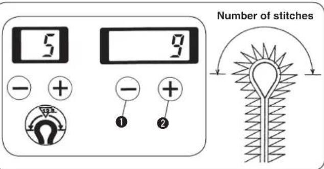

Set the number of stitches of the top section of eyelet.
Set the number of stitches with [RIGHT] key ① or [RIGHT] key ②.
The number of stitches can be set 4 to 20 stitches.
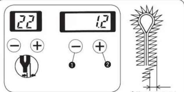
(6) Setting the cut space
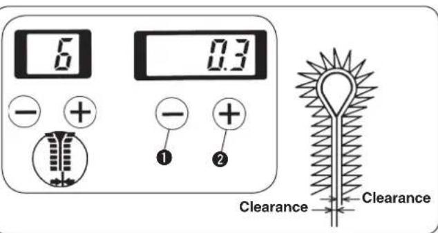

Set the clearance where the knife drops in the parallel section.
Set the cut space with [RIGHT] key① or [RIGHT] key②.
The space can be set -1.2 to 1.2 mm in the increments of 0.1 mm.
(7) Setting the eyelet space
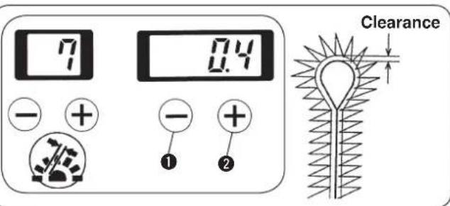

Set the clearance where the knife drops in the eyelet section.
Set the eyelet space with [RIGHT +key ① or [RIGHT ⊕] key ②.
The space can be set - 1.2 to 1.2 mm in the increments of 0.1 mm.
(8) Setting the length of taper bar
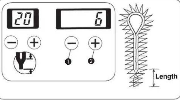

Set the length of taper bar.
1) Set the length of taper bar with [RIGHT] key ① or [RIGHT] key ②.
2) In case of without taper bar, set the value to 0 mm. In case of with taper bar, the length can be set 3 to 15 mm in the increments of 1 mm.

When the length of taper bar is changed, the number of stitches of taper bar will automatically change.
(9) Setting the number of stitches of taper bar
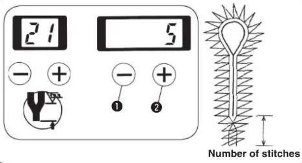

Set the number of stitches of taper bar.
Set the number of stitches of taper bar with [RIGHT

key ① or [RIGHT +] key ②.

The number of stitches can be set to such an extent of 0 to 20 stitches. The number of stitches that can be set is limited by the set value of the length of taper bar.
Example) When the length of taper bar is equal to 6 mm, the number of stitches is 2 to 12 stitches.
(10) Setting the offset of taper bar

Set the offset amount from the center of taper bar.
Set the offset amount with [RIGHT +key 1 or [RIGHT ⊕] key 2.
The offset amount can be set 0.5 mm to 2.0 mm in the increments of 0.1 mm.
(11) Setting the sewing speed
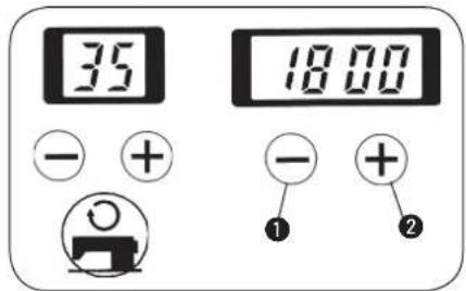

Set the sewing speed of the whole sewing.
Set the sewing speed with [RIGHT +key ① or [RIGHT ⊕] key ②.
The sewing speed can be set 400 sti/min to 2,200 sti/min in the increments of 100 sti/min.
(12) Setting the reduction speed of eyelet
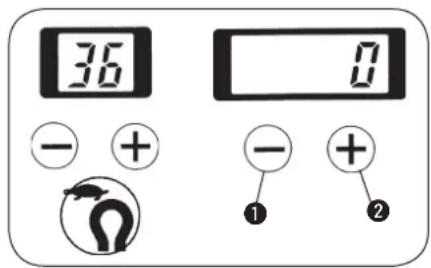

Set the reduction speed when the sewing speed of eyelet section is desired to be reduced.
Set the reduction speed with [RIGHT ⏻] key ① or [RIGHT⊕] key ②.
The speed can be set — 600 sti/min to 0 sti/min in the increments of 100 sti/min.
(13) Setting the FUNCTION F1
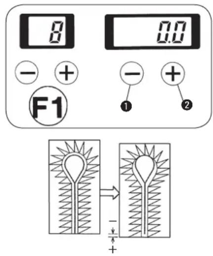

- F1 has been set to the switch of knife position compensation in the state of delivery.
- F1 performs correction of the slip between the knife position and the sewing position.
1) When the stitches in terms of the knife position are desired to be placed in the front side, set “+” (plus) value, and in the rear side, set “—” (minus) value.
2) Set the pattern No. with [RIGHT ⊖ ] key① or [RIGHT ⊕ ] key②.
The knife position compensation can be set - 0.7 mm to 0.7 mm in the increments of 0.1 mm.

This key can be changed to the key for setting other data by means of the memory switch No. 17.
(Refer to "14. MEMORY SWITCH" p.68.)
(14) Setting the FUNCTION F2
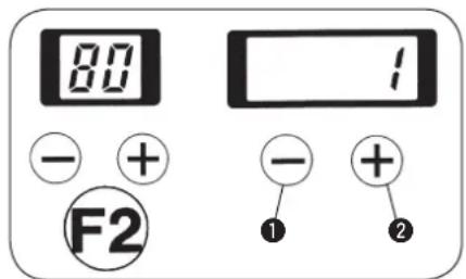

- F2 has been set to the switch of the copy destination No. in the state of delivery.
• F2 performs copying of the pattern data.
1) When setting the copy destination No. and pressing [READY Ⓞ] key, the pattern No. specified in the copy destination No. is stored in memory.
The original pattern data cannot be changed.
2) Set the pattern No. with [RIGHT] key ① or [RIGHT] key ②.
The No. can be set 1 to 89.

The pattern data located in the copy destination are overwritten. So, be careful.

When the pattern No. is changed without pressing [READY] key, or turning OFF the power, copying is not performed.

This key can be changed to the key for setting other data by means of the memory switch No. 18. (Refer to "14. MEMORY SWITCH" p.68.)
8. ADJUSTMENT OF EACH PART

WARNING : Turn OFF the power before starting the work so as to prevent accidents caused by abrupt start of the sewing machine.
(1) Replacing the cloth cutting knife and the knife holder
■ Replacing the upper cloth cutting knife and the knife holder
1) Loosen thumbscrew ① and remove knife holder and cloth cutting knife ②.
2) Make the knife holder or the cloth cutting knife desired to be replaced come in contact with stopper ③ and tighten thumbscrew ①.

Stopper ③ is for positioning. Do not move it.
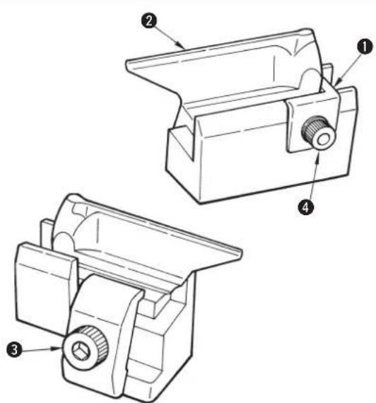
■ Lower cloth cutting knife and the knife holder
1) Loosen setscrew ③ and remove knife holder and cloth cutting knife ②.
2) Make the knife holder or the cloth cutting knife desired to be changed come in contact with stopper ① and tighten setscrew ③.

Stopper ① is for positioning. Do not loosen screw ④.

When replacing the cloth cutting knife, match the knife No. to the knife No. of the program. Use the cloth cutting knife and the knife holder as a set.
(Two different knife marks are formed and cloth cannot be precisely cut. As a result, breakage of the cloth cutting knife will be caused.)
(2) Adjusting the cloth cutting knife pressure

- The cloth cutting knife pressure and the contact time of the knife and the knife holder can be changed.
- When replacing the cloth cutting knife or the knife holder, or changing the sewing material, it is necessary to adjust the pressing amount of the knife or the stopping time of the knife lower position.
- Perform the change of set value after fully performing checking of the knife holder face and the knife.
- Gradually increase any set value from the small amount while checking the set value.
■ Adjusting the knife pressing amount
1) Pressing [ADJUST] key①, turn ON the power.
2) The pressing amount set in 4-digit LED ⑤ is displayed.
3) Press [READY Ⓞ] key ④ to light up the sewing LED. At this time, the feed base performs origin retrieval.
4) The pressing amount can be set with [RIGHT ⊖] key ② or [RIGHT ⊕] key ③.
The setting range is — 100 to 300. The more the number is, the higher the knife pressure becomes.
5) Lower the presser with the presser switch and press the start switch to actuate the knife.
The pressing amount can be set again using [RIGHT ⊖] key ② or [RIGHT ⊕] key ③ with the presser raised.
6) After setting is completed, press [ADJUST] key ① and the knife adjustment mode will end.

The set value is stored in memory when the knife is actuated by the start switch or [ADJUST] key is pressed. When turning OFF the power without performing either operation, the setting is not stored in memory

Set the knife pressing amount as small as possible in order to protect the knife and the knife holder and maintain the durability. If the knife pressing amount is excessively large, malfunction of the drive motor or breakage of the knife will be caused.

Knife holder Nos. "0" to "9" to which 10 kinds of knife pressing amounts have been set can be set to the pattern data using memory switch No. 40. (Refer to "Setting the pattern data of cloth cutting knife pressing amount", p.44.)
■ Adjusting the stopping time of the knife lower position
The stopping time at the knife lower position can be extended.
Setting of 50 to 500 ms can be performed with the memory switch No. 55.
(Refer to "14. MEMORY SWITCH" P.68.)

Even when the pressing amount is increased, the result is not effective, when the cut length is excessively long or sewing heavy-weight materials, set the stopping time of the knife lower position longer than the specified time.
(3) Worn-out of the knife holder face
Contact face of the knife holder with the cloth cutting knife.
A
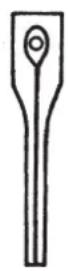
B
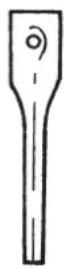
C
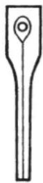
1) Remove the knife holder. (See p.26.)
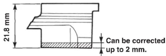
2) When the knife mark is too deep, the knife mark is duplicate (A of Fig. on the left side) by using another knife or the knife mark is partially formed and not formed on the whole surface (B of Fig. on the left side), grind the face with an oil stone or the like so that the knife mark becomes uniform.

The knife holder can be corrected up to 2 mm.
3) When the cloth cannot be precisely cut although the knife holder is properly corrected, check the state of worn-out of the blade tip of the cloth cutting knife.

- When replacing the knife, use a new knife holder or a corrected knife holder.
Breakage of the blade tip of the cloth cutting knife may occur.
2. When correcting the knife holder, adjust again the knife pressing amount.
3. When replacing the knife holder with a new one, adjust again the knife pressing amount from 30 or less.
(4) Setting the material thickness of the cloth cutting knife

When the material thickness at the cloth cutting section is excessively thick or the cut length of heavy-weight materials is long, perform the following settings. The low-speed section of the cloth cutting is increased.
1) Turn ON the memory switch.
2) Set the memory switch No. 57 or 58 to the value A or B described in the table below.
| No.57 | No.58 | |
| Standard value (Up to jeans) | 60 | 80 |
| A (Extra heavy-weight materials) | 100 | 100 |
| B (Extra heavy-weight materials and long cut length) | 150 | 120 |

- When the set value A or B is selected, the cloth cutting knife operating time is lengthened.
- When the set value is smaller than the standard one, the normal cloth cutting operation may not be performed.
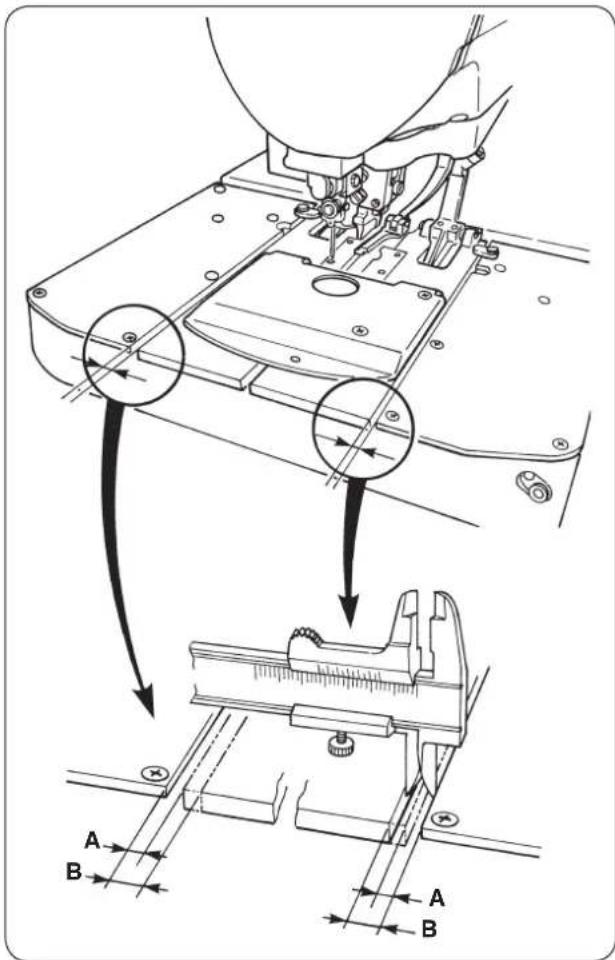
(5) Adjusting the stitch bite width

WARNING :
Turn OFF the power before starting the work so as to prevent accidents caused by abrupt start of the sewing machine.

For all types the stitch bite width which is possible to sew is up to 3.2 mm. If the width exceeds 3.2 mm, stitch skipping may occur. When the width exceeding 3.2 mm is desired to be used, use the optional looper (left) and spreader (left). However, for T type, the width is up to 3.2 mm.
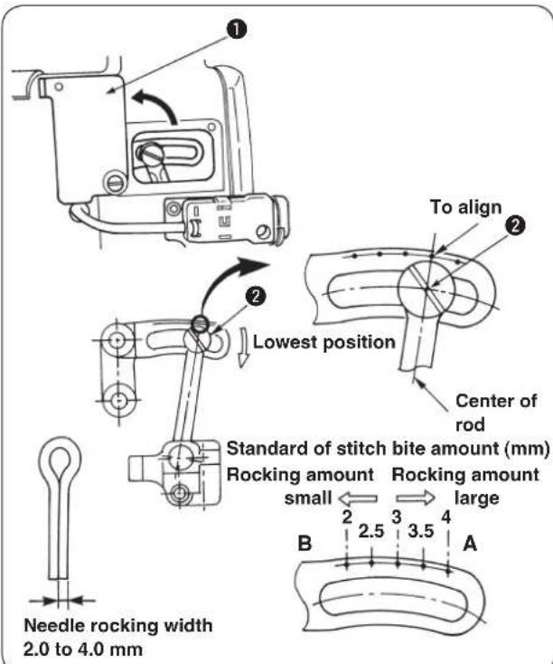
1) Open needle rocking adjustment cover ①.
2) Turn the handwheel to bring the needle bar to its lowest position.
3) Loosen fulcrum shaft ② of rocking link B.

- Moving the rocing link B in the direction A increases the stitch bite width.
- Moving the rocking link B in the direction B decreases the stitch bite width.
4) When the stitch bite width is determined, fix fulcrum shaft ② of rocking link B and close the needle rocking adjustment cover.
5) After adjusting the stitch bite width in the aforementioned steps, check the respective items of 11. (2) Timing between the needle and the looper P.45, 11. (3) Clearance between the needle and the looper P.47 and 11. (5) Installing positions of the spreaders and timing to open/close the spreaders P.48.

The engraved marker dot is a standard. Make sure of the amount by putting the needle tip marks on a sheet of paper or the like for the precise measurement.
(6) Adjusting the presser
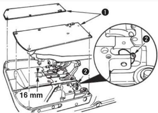
■ Adjusting the height of the presser
1) Remove auxiliary presser plate cover①.
2) Loosen screw ② and adjust the height of the presser.

The height of the presser is up to 16 mm. If the height is set to more than 16 mm, when the cloth setting position is in the front, and the presser goes up, the presser interferes with the finger guard.
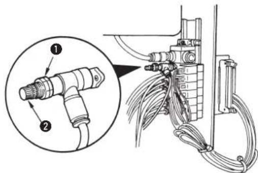
■ Adjusting the presser pressure
Loosen nut ① of the reducing valve and adjust the pressure with adjustment screw ②.

Turning the screw clockwise increases the presser pressure and turning it counterclockwise decreases the pressure.
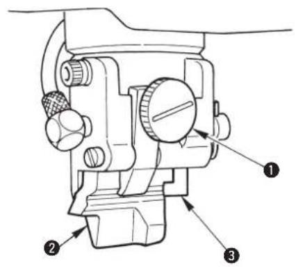
(7) Adjusting the presser opening amount
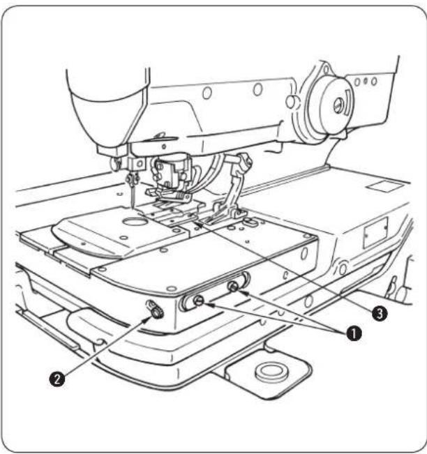
■ Adjusting procedure
Loosen setscrew ① and turn adjustment screw ② to adjust the amount.
The position where the presser plate closes will change according to the adjustment.

Turning the adjustment screw ② clockwise decreases the opening amount and turning it counterclockwise increases the opening amount.

The position of the presser (A in the figure below) at the time of sewing (in the state that the cloth open is opened) can be adjusted and the presser can be approached to the throat plate. (Refer to the Engineer's Manual.)
* At this time, there is a case where an additional processing of support plate ③ is necessary to prevent the interference of the cloth cutting knife with support plate ③.
- Checking the cloth open amount at the time of adjustment
1) Turn ON the power and press the [READY] key to light up the sewing LED.
2) Press [KNIFE ①] key to make the LED go out so that the cloth cutting knife is not actuated.
3) Press the presser switch, press [FORWARD 📊] key and the cloth open mechanism opens. The feed base travels to the sewing start position and stops there.

At this time, measure position "A" of the presser plate with vernier calipers or the like.
4) Press [RESET R] key, and the presser goes up, then the cloth open mechanism closes and returns to its origin.

At this time, measure position "B" of the presser plate with vernier calipers or the like. B — (minus) A, (difference between A and B) = cloth open amount

The cloth open amount can be adjusted within the range of 0 to 2 mm. Normally, however, the amount of 0.5 to 0.8 mm is enough.

WARNING :
The confirmation of cloth open amount can be performed by actually cutting cloth in the manual mode. However, the cloth cutting knife works. So, be careful.
(8) Adjusting the feeding amount of the needle thread
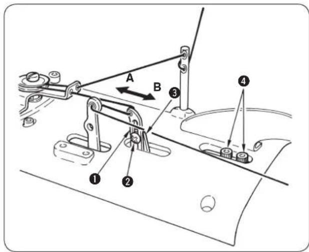
■ Adjusting the feeding amount of the needle thread during sewing
Loosen screw ② and move the position of needle thread drawing thread guide ① up or down to adjust the feeding amount.

- When the thread guide slides downward, the feeding amount of needle thread decreases and the needle thread is apt to be tightened.
- When the thread guide slides upward, the feeding amount of needle thread increases and the needle thread is difficult to be tightened.
■ Adjusting the drawing amount of the needle thread at the sewing start
Loosen screws ④ and move thread drawing arm ③ in the direction of A or B to adjust the drawing amount. When the machine is provided with the needle thread clamp unit, if the thread drawing arm is moved in the direction of A, the thread remaining on the needle will be shorter and the thread is easy to be rolled in.

When the machine is not provided with the needle thread clamp unit, and the memory switch No. B8 is "0", "Adjusting the drawing amount of the needle thread at the sewing start" cannot be performed.

- When moving it in the direction of B, the drawing amount of needle thread increases and slip-off of needle thread or the like can be prevented.
- Refer to the Instruction Manual for the needle thread clamp unit.
(9) Adjusting the thread take-up thread guide
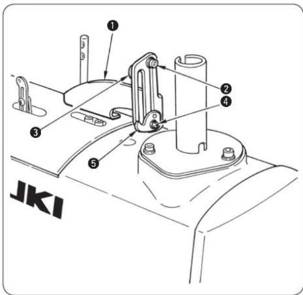
Slide up or down thread take-up thread guides ^3 and ^5 installed on thread take-up thread guide installing base ^1 and the trend described below is obtained.
■ Loosen screw ② and move do w nwa rd th r ead ta ke- up thread guide ③.
Effect: • Double chainstitch stitches can easily stand and the sewing possible area is widened. On the contrary, the whole stitches become stiff. (This is suitable for heavy-weight materials.)
• The loop when the looper catches thread becomes larger and stitch skipping is prevented. (Hard-to-slide thread)
■ Loosen screw ④ and move upward thread take-up thread guide ⑤.
Effect: Double chainstitch stitches become flat and the stitches become soft. On the contrary, the sewing possible area is narrowed and stitch skipping is apt to occur. (This is suitable for light-weight materials.)
(10) Adjusting the remaining amount of the gimp (J and C types)
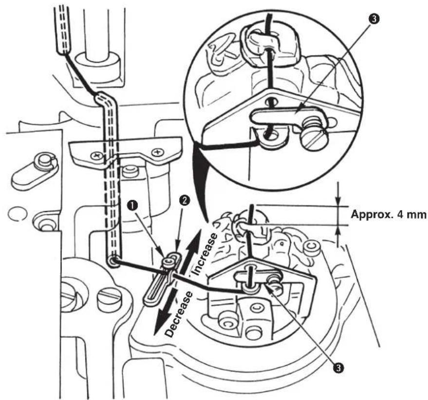
1) Loosen setscrew ① and move to and fro gimp guide ② to adjust the remaining amount of the gimp at the sewing end.
2) For the adjustment, actually sew the remainder of the material or the like and determine the position of gimp guide ② so that the remaining length of the gimp is approximately 4mm at the sewing end.

There is a case where the remaining amount of gimp is not stable when sewing thread or the like is used for the gimp. In this case, insert the gimp in the gimp presser plate ③.
(11) Adjusting the gimp thread tension (J and C types)
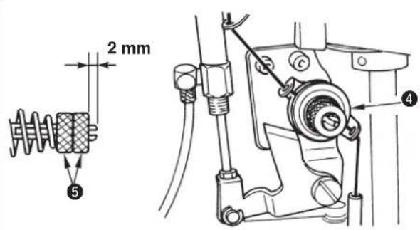
Loosen double nut ⑤ to adjust the tension. The standard adjustment value is 2 mm.
When double nut ⑤ is tightened, the gimp tension becomes higher and the length of remaining thread at the time of looper thread trimming becomes shorter. On the contrary, the length of remaining gimp becomes unstable, or the looper thread trimming knife may cut the stitches or materials in case of lightweight materials or elastic sewing products.

-
In case of the light-weight materials or stretchy sewing products, loosen nut ⑤ and fix it.
-
When gimp thread tensio is excessively low or high, there is a case where the length of remaining gimp becomes unstable. The standard adjustment value is 2 mm. Nut⑤ consists of a double nut for locking.
9. COMPENSATION OF THE DATA
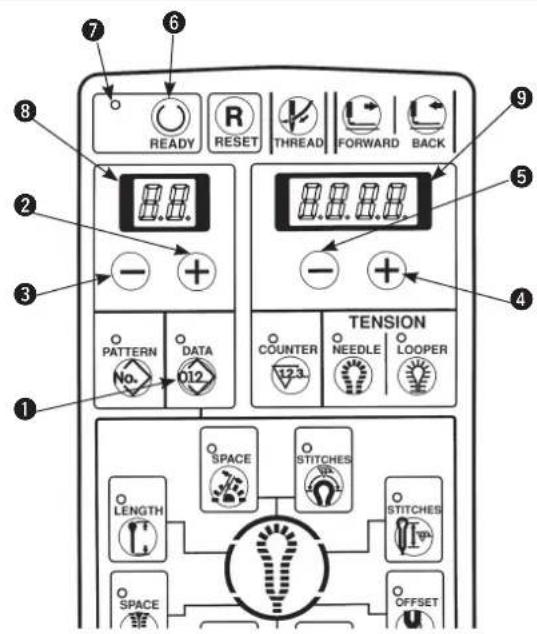
1) Confirm that sewing LED ⑦ has gone out. When the LED lights up, press [READY] key ⑥ to make it go out.
2) Display the pattern No. desired to be changed.
3) Press [DATA 012] key ① to display the data.
4) Press [LEFT ⊕] key ② or [LEFT ⊖] key ③ to display the data No. of the part desired to be changed.
5) Press [RIGHT+] key4 or [RIGHT-] key5 and re-set the respective data.
6) Press [READY Ⓞ] key ⑥ to light up sewing LED ⑦ and the data are stored in memory.

When changing the pattern No. without pressing [READY ⏻] key ⑥ or turning OFF the power, the data are not stored in memory. It is necessary to set again the data.
7) When the memory switch No. 20 is equal to "1", change of setting the data in step 5) can be prohibited.

The data No. is stated in 2-digit LED ⑧ and the example of the set value is stated in 4-digit LED ⑨ as shown below. The setting range is stated in the respective sentences.

Stitches of the respective compensations as shown below are expressed by the stitches as observed from the right side of stitching.
Wrong side of stitching
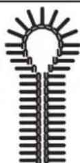
Right side of stitching
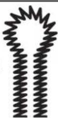
(1) Knife position compensation
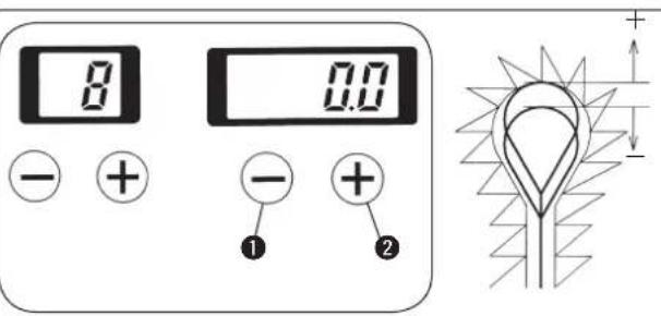

Correct the slip between the position of knife and sewing position.
1) When the knife position in terms of the stitches is desired to be placed in the rear side, set “+” (plus) value, and in the front side, set “-” (minus) value.
2) Set the knife position with [RIGHT] key① or [RIGHT] key②. Setting can be performed—0.7 to 0.7 mm in the increments of 0.1 mm.
(2) Number of stitches of sewing end compensation
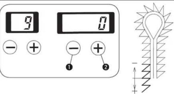

Number of stitches of sewing end can be increased at the same sewing pitch.
Set the number of stitches with [RIGHT] key① or [RIGHT] key②.
Setting can be performed as follows :
Without bartack ... — 1 to 6 stitches
Taper bar ... — 1 to 6 stitches
Straight bar ... — 1 to 3 stitches
(3) Compensation of turning
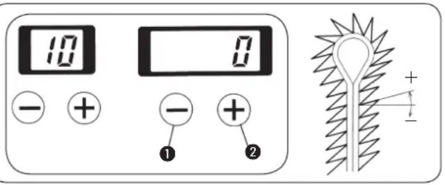

Turning angle of the eyelet section and of the parallel section can be adjusted.
Set the turning angle with [RIGHT +key ① or [RIGHT ⊕] key ②.
Setting can be performed — 14^ to 14^ .
(4) Parallel section turning compensation
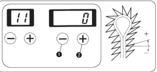

Turning angle of parallel section and bottom of eyelet can be adjusted.
Set the turning angle with [RIGHT +key 1 or [RIGHT ⊕] key 2.
When the turning compensation of the aforementioned (3) is performed, the compensation is performed in the form of adding the compensation value of turning of (3).
Setting range is -14 ≤ compensation of turning + compensation of turning at parallel section ≤ 14.
(5) Eyelet crosswise compensation


Position on the top of eyelet can be moved to the right- or left-hand.
Set the position with [RIGHT] key① or [RIGHT] key②.
Setting can be performed — 0.6 to 0.6 mm in the increments of 0.1 mm.
(6) Eyelet lengthwise compensation
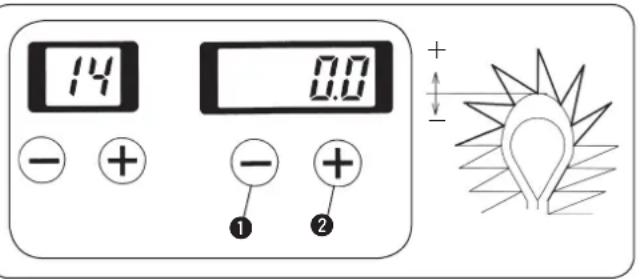

Shape on the top of eyelet can be expanded or contracted in the longitudinal direction.
Set the position with [RIGHT] key① or [RIGHT] key②.
Setting can be performed — 0.2 to 0.6 mm in the increments of 0.1 mm.
(7) Left eyelet lengthwise compensation
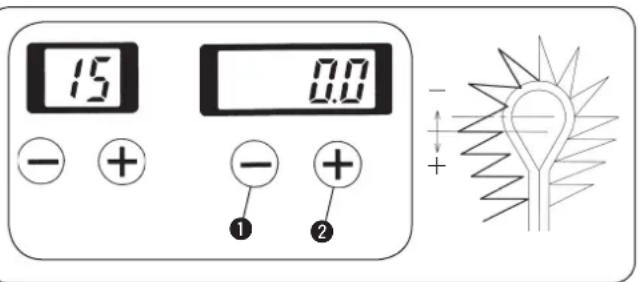

Length of the left side on the top of eyelet can be adjusted.
Set the length with [RIGHT ⊖] key ① or [RIGHT ⊕] key ②.
Setting can be performed — 0.2 to 0.6 mm in the increments of 0.1 mm.
(8) Left parallel section lengthwise compensation
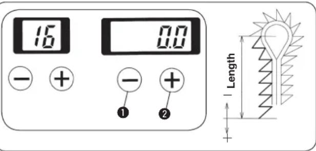

Length from the bottom of eyelet to the left side of parallel section can be adjusted.
Set the length with [RIGHT] key① or [RIGHT] key②.
Setting can be performed - 0.6 to 0.6 mm in the increments of 0.1 mm.
(9) Needle throwing width of the right bottom of eyelet setting
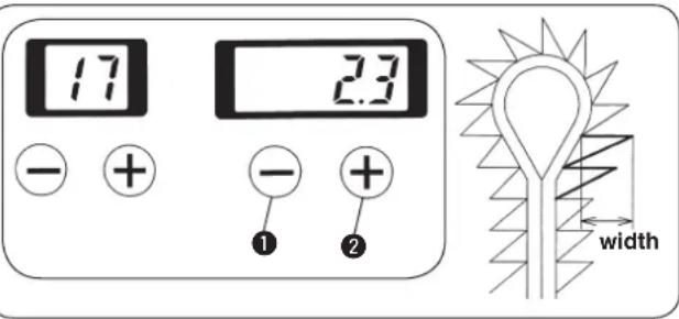

- Needle throwing width of the right side of the bottom of eyelet can be set.
- Feed base is actuated with the needle throwing to change the sewing width.
Set the width with [RIGHT ⊖] key ① or [RIGHT ⊕] key ②. The width can be set within the range of 2.3 ±1.0 mm for S type, 2.5 ± 1.0 mm for J type, 2.5 ± 1.0 mm for C type and 2.3 ± 1.0 mm for T type in the increments of 0.1 mm.
(10) Needle throwing width of the left bottom of eyelet setting
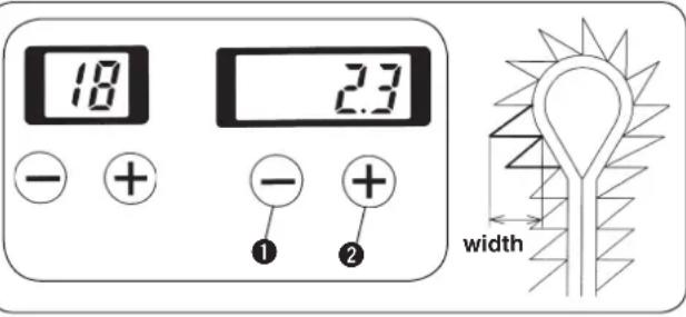

- Needle throwing width of the left side of the bottom of eyelet can be set.
- Feed base is actuated with the needle throwing to change the sewing width.
Set the width with [RIGHT —] key ① or [RIGHT +] key ②. The width can be set within the range of 2.3 ±1.0 mm for S type, 2.5 ± 1.0 mm for J type, 2.5 ± 1.0 mm for C type and 2.3 ± 1.0 mm for T type in the increments of 0.1 mm.
(11) Needle throwing width setting
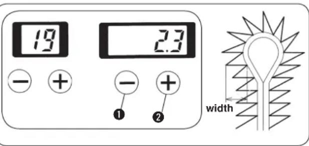

- Needle throwing width of the whole buttonholing can be set.
- Feed base is actuated with the needle throwing to change the sewing width.
Set the width with [RIGHT] key ① or [RIGHT] key ②. The width can be set within the range of 2.3 ±1.0 mm for S type, 2.5 ± 1.0 mm for J type, 2.5 ± 1.0 mm for C type and 2.3 ± 1.0 mm for T type in the increments of 0.1 mm.
(12) Number of stitches of the slant taper bar
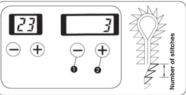

Number of stitches of the slant section from the taper bar to the parallel section can be set.
Set the number of stitches with [RIGHT] key① or [RIGHT] key②.
Setting can be performed 2 to 30 stitches within the range of number of stitches of the taper bar.
(13) Number of stitches of the right side taper bar compensation
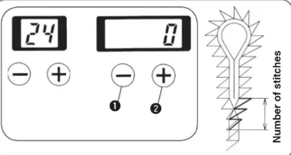
Number of stitches of the right side taper bar can be decreased and the overlapping section can be made less.
Set the number of stitches with [RIGHT] key ① or [RIGHT] key ②.
Setting can be performed — 30 to "0" stitch within the range of number of stitches of the taper bar.
(14) Shape of the straight bar
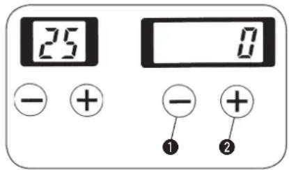

Shape of the straight bar can be selected.
1) Set the shape with [RIGHT-] key ① or [RIGHT+] key ②.
2) Set the value to "0" in case of without straight bar.
3) In case of with straight bar, select the shape from among No. 1 to No. 90 of the table below.
4) When making memory switch No. 26 = 1, it is possible to sew the pattern with straight bar with the cloth open mechanism opened.
| No. (a) | Length stitches | Number of (n) | overlapping amount(b) | Needle throw width(c) |
| 1 | 3.0 | 4 | 1.0 | 0 |
| 2 | 4.0 | 5 | 1.0 | 0 |
| 3 | 5.0 | 6 | 1.0 | 0 |
| 4 | 6.0 | 7 | 1.0 | 0 |
| 5 | 7.0 | 8 | 1.0 | |
| 6 | 8.0 | 9 | 1.0 | |
| 7 | 3.0 | 5 | 1.0 | 0 |
| 8 | 4.0 | 6 | 1.0 | 0 |
| 9 | 5.0 | 7 | 1.0 | 0 |
| 10 | 6.0 | 9 | 1.0 | 0 |
| 11 | 7.0 | 10 | ||
| 12 | 8.0 | 11 | ||
| 13 | 3.0 | 6 | 1.0 | |
| 14 | 4.0 | 8 | 1.0 | |
| 15 | 5.0 | 9 | 1.0 | |
| 16 | 6.0 | 11 | ||
| 17 | 7.0 | 13 | ||
| 18 | 8.0 | 14 |
| No. (a) | Length stitches | Nuber of (n) | Overlapping amount(b) | Needle throw width(c) | |
| 19 | 3.0 | 4 | 1.5 | 0 | |
| 20 | 4.0 | 5 | 1.5 | 0 | |
| 21 | 5.0 | 6 | 1.5 | 0 | |
| 22 | 6.0 | 7 | 1.5 | 0 | |
| 23 | 7.0 | 8 | 1.5 | ||
| 24 | 8.0 | 9 | 1.5 | ||
| 25 | 3.0 | 5 | 1.5 | 0 | |
| 26 | 4.0 | 6 | 1.5 | 0 | |
| 27 | 5.0 | 7 | 1.5 | 0 | |
| 28 | 6.0 | 9 | 1.5 | 0 | |
| 29 | 7.0 | 10 | 1.5 | -0.5 | |
| 30 | 8.0 | 11 | 1.5 | -1.0 | |
| 31 | 3.0 | 6 | 1.5 | 0 | |
| 32 | 4.0 | 8 | 1.5 | 0 | |
| 33 | 5.0 | 9 | 1.5 | 0 | |
| 34 | 6.0 | 11 | 1.5 | 0 | |
| 35 | 7.0 | 13 | 1.5 | -0.5 | |
| 36 | 8.0 | 14 | 1.5 | -1.0 |
Select the shape of straight bar from the left-hand table.
| a | Length |
| n | Number of stitches |
| b | Overlapping amount |
| c | Needle throw width |
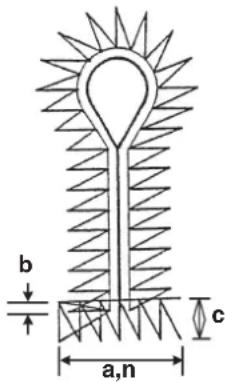
| No. (a) | Length stitches(n) | Nuber of amount(b) | Overlapping width(c) | Needle throw |
| 37 | 3 | 0 4 1.0 | -0.5 | |
| 38 | 4 | 0 5 1.0 | -0.5 | |
| 39 | 5 | 0 6 1.0 | -0.5 | |
| 40 | 6 | 0 7 1.0 | -0.5 | |
| 41 | 7 | 0 8 1.0 | -1.0 | |
| 42 | 3 | 0 5 1.0 | -0.5 | |
| 43 | 4 | 0 6 1.0 | -0.5 | |
| 44 | 5 | 0 7 1.0 | -0.5 | |
| 45 | 6 | 0 9 1.0 | -0.5 | |
| 46 | 7 | 0 | 10 | 1.0 |
| 47 | 3 | 0 6 1.0 | -0.5 | |
| 48 | 4 | 0 8 1.0 | -0.5 | |
| 49 | 5 | 0 9 1.0 | -0.5 | |
| 50 | 6 | 0 | 11 | 1.0 |
| 51 | 7 | 0 | 13 | 1.0 |
| No. (a) | Length stitches | Number of Overlapping Need (n) amount(b) width(c) | Needle throw | |
| 52 | 3 | 0 | 4 1.5 | |
| 53 | 4 | 0 | 5 1.5 | |
| 54 | 5 | 0 | 6 1.5 | |
| 55 | 6 | 0 | 7 1.5 | |
| 56 | 7 | 0 | 8 1.5 | |
| 57 | 3 | 0 | 5 1.5 | |
| 58 | 4 | 0 | 6 1.5 | |
| 59 | 5 | 0 | 7 1.5 | |
| 60 | 6 | 0 | 9 1.5 | |
| 61 | 7 | 0 | 10 1.5 | |
| 62 | 3 | 0 | 6 1.5 | |
| 63 | 4 | 0 | 8 1.5 | |
| 64 | 5 | 0 | 9 1.5 | |
| 65 | 6 | 0 | 11 1.5 | |
| 66 | 7 | 0 | 13 1.5 | |
Select the shape of straight bar from the left-hand table.
| No. (a) | Length stitches | Nuber of (n) amount | Overlapping (b) width(c) | Needle throw |
| 67 | 3.0 4 | 1.0 | -1.0 | |
| 68 | 4.0 5 | 1.0 | -1.0 | |
| 69 | 5.0 6 | 1.0 | -1.0 | |
| 70 | 6.0 7 | 1.0 | -1.0 | |
| 71 | 3.0 5 | 1.0 | -1.0 | |
| 72 | 4.0 6 | 1.0 | -1.0 | |
| 73 | 5.0 7 | 1.0 | -1.0 | |
| 74 | 6.0 9 | 1.0 | -0.5 | |
| 75 | 3.0 6 | 1.0 | -1.0 | |
| 76 | 4.0 8 | 1.0 | -1.0 | |
| 77 | 5.0 9 | 1.0 | -1.0 | |
| 78 | 6.0 | 11 | 1.0 | -1.0 |
| No. (a) | Length N stitches(n) | Number of Overlapping Need amount(b) width(c) | Need throw width(c) |
| 79 | 3.0 4 | 1.5 | |
| 80 | 4.0 5 | 1.5 | |
| 81 | 5.0 6 | 1.5 | |
| 82 | 6.0 7 | 1.5 | |
| 83 | 3.0 5 | 1.5 | |
| 84 | 4.0 6 | 1.5 | |
| 85 | 5.0 7 | 1.5 | |
| 86 | 6.0 9 | 1.5 | |
| 87 | 3.0 6 | 1.5 | |
| 88 | 4.0 8 | 1.5 | |
| 89 | 5.0 9 | 1.5 | |
| 90 | 6.0 | 11 | 1.5 |
| a | Length |
| n | Number of stitches |
| b | Overlapping amount |
| c | Needle throw width |
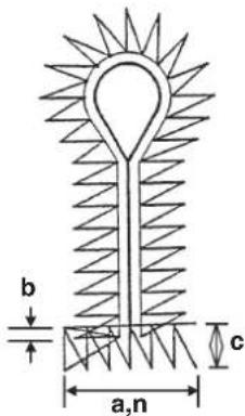
- Set the cut length to the length of the knife holder to be used plus overlapping amount (b) or more.
- Select the length (a) of the straight bar within the range where there is no interference of the throat

plate with the eyelet holding plate in consideration of the position of the presser plate when the cloth open mechanism opened.
- When the length (a) of the straight bar is lengthened, needle thread may not be clamped unless the lateral position of the needle thread clamp unit is re-adjusted. (Refer to the Engineer's Manual.)
(15) Number of stitches of the round bar
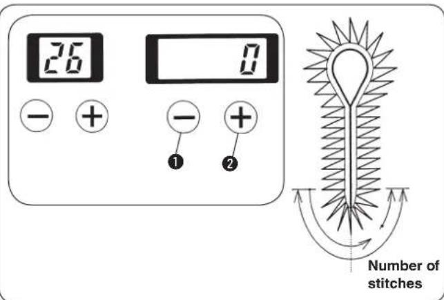

The number of stitches of the round bar is set.
1) Set the number of stitches with [RIGHT ⊖] key ① or [RIGHT ⊕] key ②.
2) In case of without the round bar, set the value to "0".
3) In case of entering the round bar, 4 to 20 stitches can be set.
4) When the round bar has been set, the number of overlapped stitches of sewing start and sewing end can be set with the number of stitches of sewing end compensation of data No. 9.
(16) Left side cut space compensation
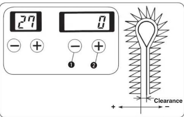

The clearance where the knife drops in the left side of the parallel section can be compensated.
Set the clearance with [RIGHT —] key ① or [RIGHT +] key ②. If the setting is “+”, the clearance becomes larger than that on the right side, and if it is “-”, the clearance becomes smaller.
Setting range is limited by the set value of the cut space of No. 6.
Cut space setting range is -1.2 ≤ cut space + compensation of left cut space ≤ 1.2.
(17) Soft start
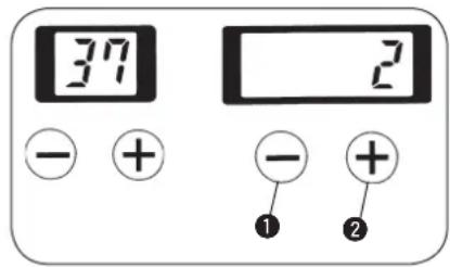

Sewing speed at the sewing start can be limited.
Set the sewing speed with [RIGHT] key ① or [RIGHT] key ②. Setting can be performed up to 6 rotations at the sewing start.

Sewing speed per rotation can be set with memory switches Nos. 1 to 6. All machines have been delivered with the speed set to 600 sti/min.
(18) Number of stitches of the sewing start of thread tension
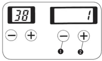

Number of stitches of the sewing start section at the time of needle/looper thread tension setting can be set.
Set the number of stitches with [RIGHT] key ① or [RIGHT] key ②.
Setting can be performed "0" to 3 stitches.
(19) Number of stitches of the sewing end of thread tension
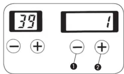

Number of stitches of the sewing end section at the time of needle/looper thread tension setting can be set.
Set the number of stitches with [RIGHT] key ① or [RIGHT] key ②.
Setting can be performed "0" to 3 stitches.
(20) Copy destination No.
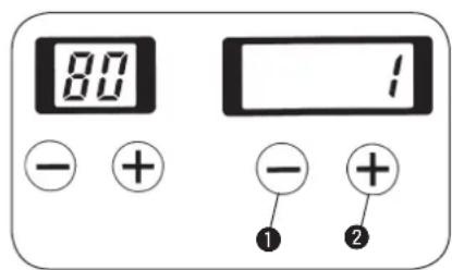

By setting a copy destination No. which is different from the pattern No. currently selected, when pressing [READY] key to light up the sewing LED, the pattern is copied in the pattern No. which has been set in the copy destination No. and stored in memory. The original pattern is not changed.

When changing the pattern No. without pressing [READY] key or turning OFF the power, the set value is not stored in memory.
1) When setting the copy destination No. and pressing [READY] key, the pattern No. specified in the copy destination No. is stored in memory. The original pattern data cannot be changed.
2) Set the pattern No. with [RIGHT] key ① or [RIGHT] key ②. The No. can be set 1 to 89.

Pattern located in the copy destination is overwritten. So, be careful.
10. HOW TO USE THE VARIOUS FUNCTIONS
(1) Performing procedure of the cycle sewing
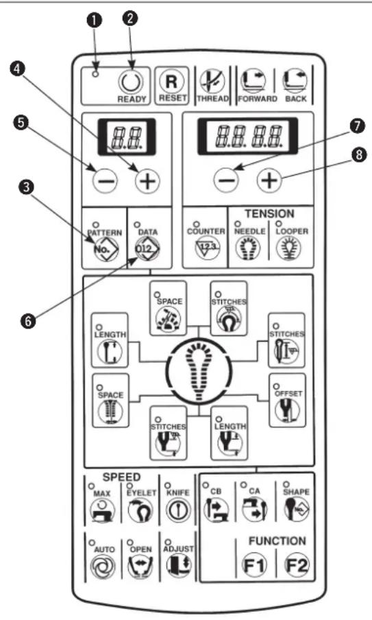

For the cycle sewing, three programs, C1 to C3, can be registered and maximum 15 different kinds of patterns (1 to 15 steps) in the respective programs can be sewn in order. (Set the data with individual patterns in advance before registration.)
1) Make sure that sewing LED ① has gone out.
When it lights up, press [READY ①key ② to make it go out.
2) Press [PATTERNNo.] key③ to display the pattern No.
3) Press [LEFT ⊕] key④ or [LEFT ⊖] key⑤ to select the program No. desired to register. (C1 to C3)
4) Press [DATA012] key6.
5) Press [LEFT ⊕] key ④ or [LEFT ⊖] key ⑤ to display the step of cycle sewing.
6) Press [RIGHT⊕] key⑧ or [RIGHT⊖] key⑦ to set the individual pattern No.
7) Repeat the steps 5) to 6) and when the setting is completed, display the next step and make the display of individual pattern No. [ ][ ] (no light-up). Then press [READY Ⓞ] key ② to light up sewing LED ① and the program is stored in memory.

- When [READY Ⓞ] key ② is pressed with the display of pattern No. [ ] [ ] (no light-up), the pattern after the step will be deleted.
- When changing the cycle sewing without pressing [READY] key2 or turning OFF the power, the data is not stored in memory.
When you desire to return the pattern to the previous one or to skip to the next one at the time of stop of the sewing machine during sewing, press [LEFT +] key ④ or [LEFT -] key ⑤. (It is effective only when the presser goes up.) Display of the pattern No. changes.

When the data is changed with each pattern, the contents registered in C1 to C3 also change. So, be careful.
Example of display
Step 1 and pattern No. 11 of cycle sewing 1 (C1)
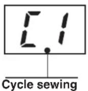
Program No.: C1 to C3
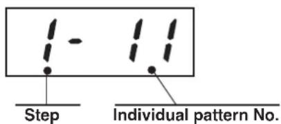
1 to 9
1 to 99
A,b,C,d,E,F
(2) Operating procedure of thread tension compensation of each section
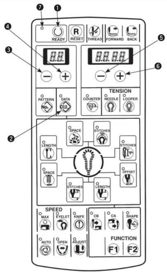

Thread tension of each section of the sewing shape can be individually changed. Thread tension at each section is needle thread tension set value (No. 40) or looper thread tension set value (No. 60) to which each compensation value has been added.
1) Make sure that the sewing LED ⑦ has gone out. When it lights up, press [READY] key ① to make it go out.
2) Press [DATA012] key②.
3) Select the compensation position No. of each tension with [LEFT ⊖] key ③ or [LEFT ⊕] key ④. (For the compensation position No., refer to the separate tables 1 and 2.)
4) When the compensation position No. is selected, input the set value with [RIGHT —] key or [RIGHT +] key 6.
5) Press [READY Ⓤkey ① and the set value is stored in memory.

Both needle thread and looper thread can be set with the same operation. When changing the pattern No. without performing the operation of step 5) or turning OFF the power, the set value is not stored in memory.

For the cpmpensation position No., refer to tables 1 and 2 and Figs. 1 and 3.
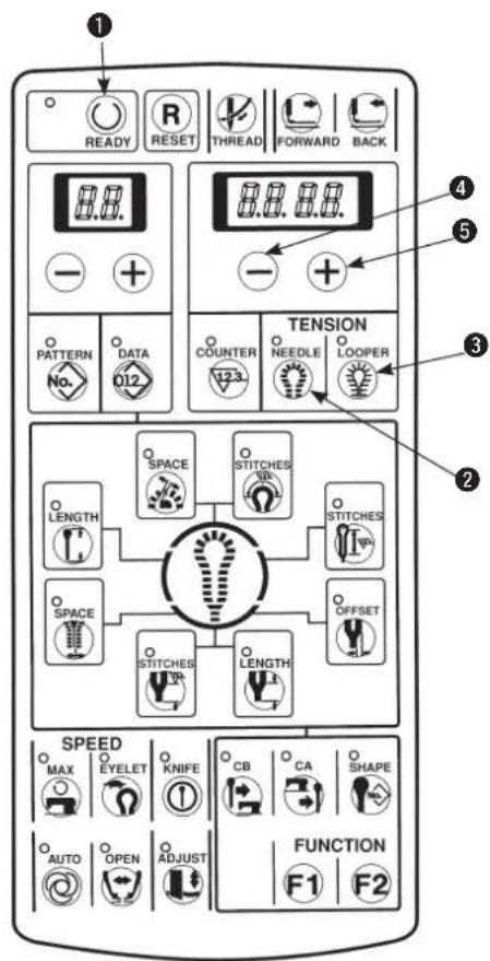
■ Performing the compensation of thread tension in the state of sewing
Setting of compensation of thread tension and confirmation of sewing can be performed without performing the operation of [READY Ⓞ] key ①.
1) Make the memory switch No. 19 = 1.
2) Directly indicate the compensation position No. with [NEEDLE ②] key ② or [LOOPER ③] key ③.
3) Set the compensation value with [RIGHT ⊖] key ④ or [RIGHT ⊕] key ⑤.
4) When pressing [READY ⏻] key ① or starting sewing with the start switch, the set value is stored in memory.

When changing the pattern No. without performing the operation of step 4) or turning OFF the power, the set value is not stored in memory.
[ Setting of needle thread tension ] Table1
| Compensation position No. | Setting item | Description |
| 40 | Needle thread tension | Needle thread tension value |
| 41 | Compensation of needle thread tension of right parallel section | Compensation value of needle thread tension of right side of parallel section |
| 42 | Compensation of needle thread tension of left parallel section | Compensation value of needle thread tension of left side of parallel section |
| 43 | Compensation of needle thread tension of top eyelet | Compensation value of thread tension of top eyelet |
| 44 | Compensation of needle thread tension of right bottom of eyelet | Compensation value of needle thread tension of right bottom of eyelet |
| 45 | Compensation of needle thread tension of left bottom of eyelet | Compensation value of needle thread tension of left bottom of eyelet |
| 46 | Compensation of needle thread tension of right taper bar | Compensation value of needle thread tension of right taper bar |
| 47 | Compensation of needle thread tension of left taper bar | Compensation value of needle thread tension of left taper bar |
| 48 | Compensation of needle thread of straight bar | Compensation value of needle thread tension of straight bar |
| 49 | Compensation of needle thread tension of right round bar | Compensation value of needle thread tension of right round bar |
| 50 | Compensation of needle thread tension of left round bar | Compensation value of needle thread tension of left round bar |
| 51 | Compensation of needle thread tension of sewing start | Compensation value of needle thread tension of sewing start |
| 52 | Compensation of needle thread tension of sewing end | Compensation value of needle thread tension of sewing end |
| 53 | Compensation of needle thread tension at the time of thread trimming | Compensation value of needle thread tension at the time of thread trimming of sewing machine * 1 |
| 54 | Compensation of needle thread tension at the time of stop | Compensation value of needle thread tension at the time of stop of sewing machine * 2 |
* 1 : Compensation value as against memory switch No. 7 (needle thread tension at the time of thread trimming)
* 2 : Compensation value as against memory switch No. 9 (needle thread tension at the time of stop)
(See the item of the memory switch on page 68.)
[ Setting of looper thread tension ] Table2
| Compensation position No. | Setting item | Description |
| 60 | Looper thread tension | Looper thread tension value |
| 61 | Compensation of looper thread tension of right parallel section | Compensation value of looper thread tension of right side of parallel section |
| 62 | Compensation of looper thread tension of left parallel section | Compensation value of looper thread tension of left side of parallel section |
| 63 | Compensation of looper thread tension of top eyelet | Compensation value of looper thread tension of top eyelet |
| 64 | Compensation of looper thread tension of right bottom of eyelet | Compensation value of looper thread tension of right bottom of eyelet |
| 65 | Compensation of looper thread tension of left bottom of eyelet | Compensation value of looper thread tension of left bottom of eyelet |
| 66 | Compensation of looper thread tension of right taper bar | Compensation value of looper thread tension of right taper bar |
| 67 | Compensation of looper thread tension of left taper bar | Compensation value of looper thread tension of left taper bar |
| 68 | Compensation of looper thread tension of straight bar | Compensation value of looper thread tension of straight bar |
| 69 | Compensation of looper thread tension of right round bar | Compensation value of looper thread tension of right round bar |
| 70 | Compensation of looper thread tension of left round bar | Compensation value of looper thread tension of left round bar |
| 71 | Compensation of looper thread tension of sewing start | Compensation value of looper thread tension of sewing start |
| 72 | Compensation of looper thread tension of sewing end | Compensation value of looper thread tension of sewing end |
| 73 | Compensation of looper thread tension at the time of thread trimming | Compensation value of looper thread tension at the time of thread trimming of sewing machine * 1 |
| 74 | Compensation of looper thread tension at the time of stop | Compensation value of looper thread tension at the time of stop of sewing machine * 2 |
* 1 : Compensation value as against memory switch No. 8 (looper thread tension at the time of thread trimming)
* 2 : Compensation value as against memory switch No. 10 (looper thread tension at the time of stop)
(See the item of the memory switch on page 68.)

- The actual thread tension varies in accordance with the kind or thickness of thread used even when the set value of thread tension is the same. Especially, in case of thread of which the surface is hard to slide, the thread tension becomes higher, and even when the set value is as low as 60 to 70, the loop becomes smaller. As a result, stitch skipping may be caused. When using plural threads, it is recommended to make a sewing pattern to which set values of thread tension suitable for the respective threads have been inputted.
- When the needle thread tension (No. 52) at the end of sewing is set to a high value, stitch skipping at the end of sewing or failure of needle thread take-up may occur.
[Compensation position of taper bar]
Fig. 1
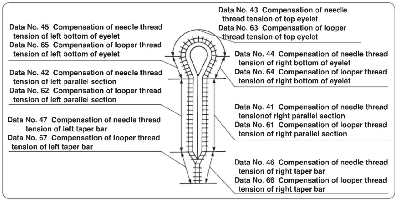
[Compensation position of straight bar]
Fig. 2
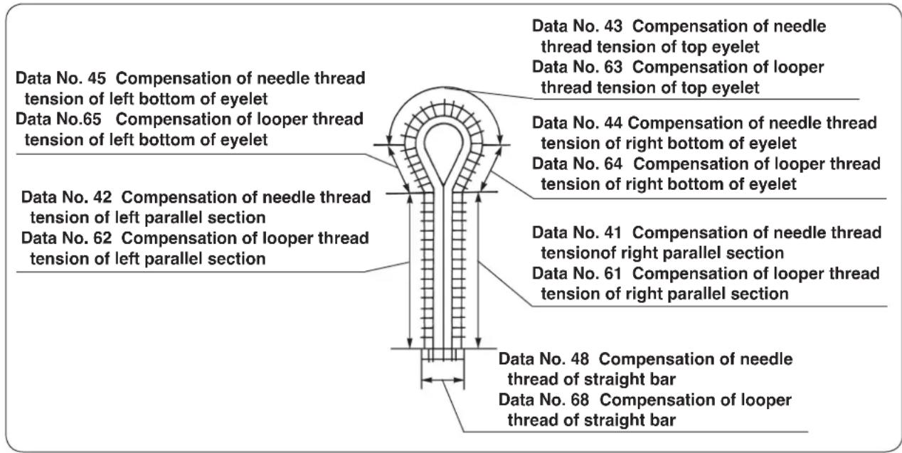
[Compensation position of round bar]
Fig. 3
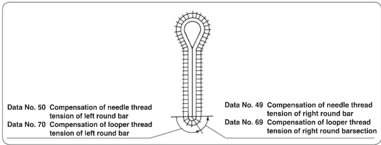
(3) Changing the setting position of cloth
Setting position of cloth can be changed to the front side.
1) Set memory switch No. 11 to "1".

Traveling amount to the front side is set by memory switch No. 29. (22 mm in the standard state of delivery) Setting "0" to 64 mm (S/R types) or "0" to 54 mm (J/C/T types) can be performed. However, if the amount is excessively large, looper thread may not be clamped.
(4) Changing over the mode of the start switch
The presser comes down by the operation of the start switch only, and the sewing is continually performed. 1) Set memory switch No. 14 to "1".

It is also possible to perform the normal use by lowering the presser with the presser switch and performing sewing with the start switch. However, the presser LED of the hand switch is always put in the state of flashing on and off.
(5) Changing over the presser movement
It is possible that the presser returns to the set position while it is held lowered after completion of sewing. (The presser returns to the set position while it is raised after completion of sewing in the standard state of delivery.)
1) Set memory switch No. 23 to "1".
2) The presser is held lowered when the sewing machine is stopped during sewing with the temporary stop switch or when the feed base returns to the set position with [RESET R] key.
(6) Changing over the counter (DOWN counting)
Set the count value and perform DOWN counting. It is possible to prohibit the start at the count value "0".
■ Change-over to DOWN counter
1) Set memory switch No. 12 to 2.
2) When the count value becomes "0", the display flashes on and off and the start switch is inoperative.
3) Press [RESET R] key and the count value returns to the initial value.
(State of standard delivery : initial value = 100)
In order to perform the start even when the count value becomes "0", set memory switch No. 13 to "0".
■ Setting the initial value of DOWN counter
It is necessary to set the initial value starting "Count DOWN" when using DOWN counter.
1) Press [COUNTER ^123 ] key to display the counter.
2) Press [RESET R] key to return the count value to the initial value.
The initial value has been set to 100 in the state of standard delivery.
3) Set the count value with [RIGHT] key or [RIGHT] key.
(7) Stop before cloth cut mode
The sewing can be temporarily stopped before performing the cloth cutting operation at the time of the pattern sewing of cut-after knife data.
1) Set memory switch No. 24 to "1".
The sewing machine once stops after sewing and cloth cutting operation is performed by again pressing the start switch.
It is also possible to return the sering machine to the cloth set position without performing cloth cutting operation by pressing [RESET R] key.
(8) Setting the pattern data of cloth cutting knife pressing amount
The cloth cutting knife pressing amount can be set to the pattern data, and even when the knife holder is replaced, the knife adjustment is not performed. The setting can be completed by changing the pattern No. only.
The knife holder No. 0 to 9 up to 10 kinds are set to the pattern data No. 28 and the knife pressing amounts can be set to each of knife holder Nos.
1) Set memory switch No. 40 to "1".
■ Adjusting the knife pressing amount
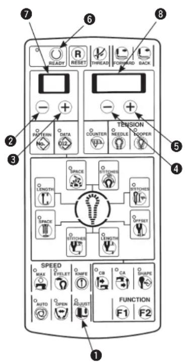
1) Pressing [ADJUST ⬆] key ①, turn ON the power.
2) The knife holder No. is displayed in 2-digit LED and the knife pressing amount which has been set to each knife holder No. is displayed in 4-digit LED ⑧.
3) Press [READY] key ⑥ to light up the sewing LED. At this time, the feed base and the cloth cutting knife perform origin retrieval.
4) The knife holder No. desired to be set can be set with [LEFT] key ② or [LEFT] key ③. The setting range is 0 to 9.
5) The knife pressing amount in terms of the knife holder No. displayed in the 2-digit LED can be set with [RIGHT ⊖] key ④ or [RIGHT ⊕] key ⑤. The setting range is -100 to 300. The more the number is, the higher the cloth cutting knife pressure becomes.
6) Lower the presser with the presser switch and press the start switch to actuate the knife. The knife holder No. can be set again with the presser raised using [LEFT ⏻] key ② or [LEFT ╒] key ③. In addition, the pressing amount can be set again using [RIGHT ⏱] key ④ or [RIGHT ╒] key ⑤.
7) Press [ADJUST 1] key 1 after completion of setting and the knife adjustment mode ends.

The set value is stored in memory when the knife is actuated by the start switch or [ADJUST] key is pressed. When changing the knife holder No. without performing either operation, or turning OFF the power, the setting is not stored in memory.

For the caution regarding adjusting the cloth cutting knife pressure, refer to (2) Adjusting the cloth cutting knife pressure on page 27.
■ Pattern data setting procedure
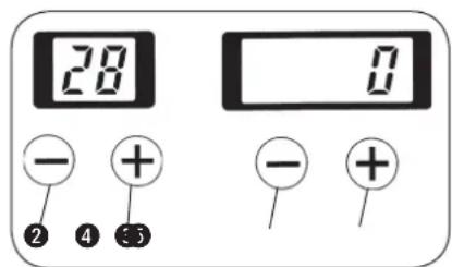

The knife holder No. to which the knife pressing amount has been set is set.
For the data setting procedure, refer to Compensation of the data on page 31.
1) Press [LEFT] key ② or [LEFT] key ③ to display data No. 28.
2) Press [RIGHT] key ④ or [RIGHT] key ⑤ to set the data No. 0 to 9 can be set.
11. MAINTENANCE
(1) Height of the needle bar

WARNING :
Turn OFF the power before starting the work so as to prevent accidents caused by abrupt start of the sewing machine.
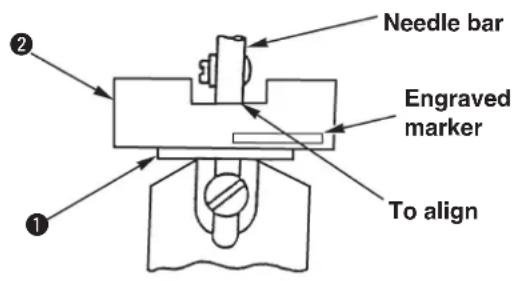
Adjust the standard position of the needle bar, using the timing gauge supplied with the machine, when the needle bar is brought to the inside lowest position following the procedure described below.
1) Remove the throat plate. Instead of the throat plate, attach timing gauge support base supplied with the machine on the machine.
2) Place timing gauge ② supplied with the machine on timing gauge support base ①, and confirm that the needle bar aligns with the indented part of the timing gauge when the needle bar is in its inside lowest position.

There are two kinds of timing gauges ②.
- With engraved marker "32021404" for S/R/J/C types
- Without engraved marker for T type
(2) Timing between the needle and the looper

DANGER :
Be sure carry out the work while observing the following in order to protect against pinching of hands, fingers and arms between the sewing machine and the bottom cover, which can result in serious injury, when you raise the sewing machine from its home position.
- Be sure to lock the hinge stopper to firmly secure the sewing machine in its raised position.
* Read and check how to rise/return the sewing machine described on p.3 to p.5.
WARNING :
Turn OFF the power before starting the work so as to prevent accidents caused by abrupt start of the sewing machine.
1)
2)
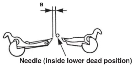
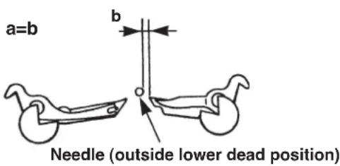
1) Bring the needle bar to its inside lowest position, loosen lower shaft sprocket setscrews ⑥ and move looper driving cam ③ so that the plane of looper driving cam ③ faces to the front. Then temporarily tighten the screws.

The maximum stitch bite width of all types is 3.2 mm. When the width exceeds 3.2 mm, use the optional looper (left) and spreader (left).

Perform the work after checking the stitch bite width and the height of the needle bar.

The stitch bite width of each type at the time of delivery is as shown in the table below.
| SS/RS JS/CS TS | |
| 2.3 2.5 2.3 |

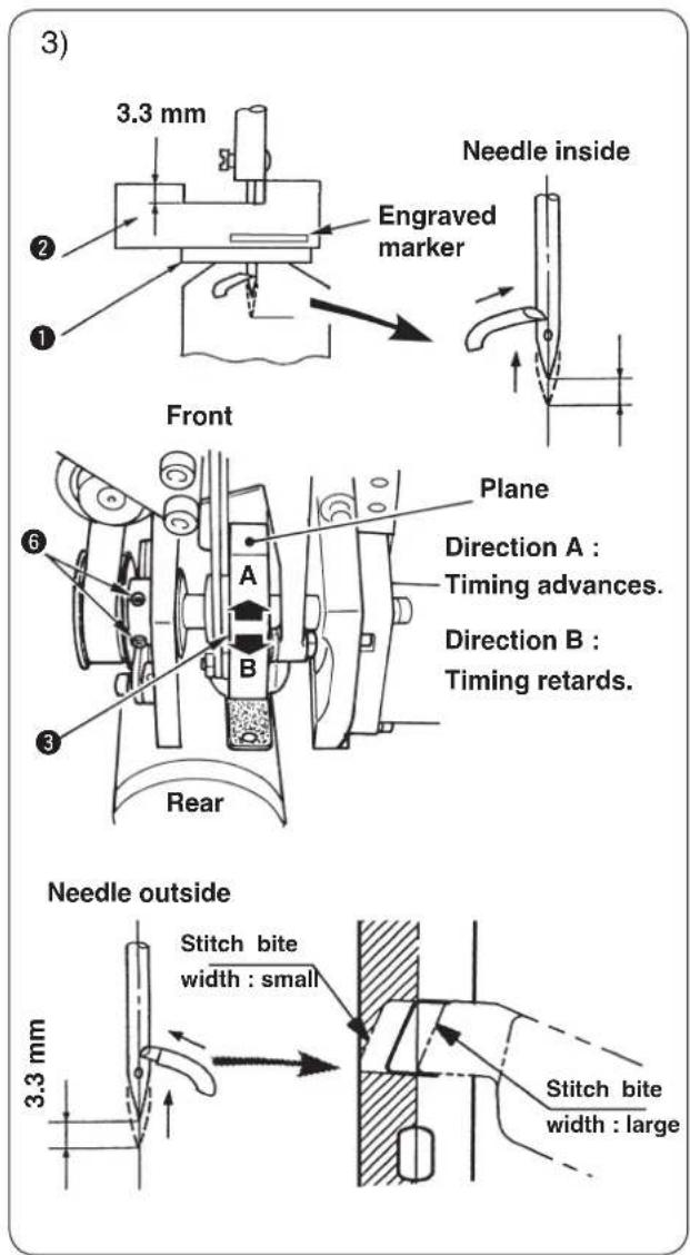
2) Loosen looper driving shaft guide setscrew ^5 and move up and down looper driving shaft guide ^4 to adjust so that the space between the needle and the left/right loopers becomes the same when the needle is brought to its outside lowest position or inside lowest position. Tighten setscrew ^5 .
3) Place timing gauge ^2 on timing gauge support base ① supplied with the machine and adjust using looper driving cam ③ so that the left looper blade point aligns with the center of the needle when the needle bar ascends 3.3 mm from the inside lowest position, and fix lower shaft sprocket setscrew ^5 . 4) Similarly, check the position of the needle and the looper blade point when the needle bar ascends 3.3 mm from the outside lowest position. The blade point is positioned approximately in the range of the left side of the needle. When it is outside the range, check again steps 2) and 3).
- After performing the looper timing adjustment, when the stitch bite width is changed in case of ① to ③ described below, perform steps 1) to 4) whenever the case occurs.
① When the stitch bite width in terms of that at the time of looper timing adjustment is changed more than ± 0.3 mm.
Even when the change of the stitch bite width is within ±0.3 mm :
② When the stitch bite width is more than 3.4 mm.
③ When sewing heavy-weight materials or overlapped section where needle is apt to be bent. - There are two kinds of timing gauges ^② .
- With engraved marker "32021404" for S/R/J/C types
- Without engraved marker for T type
(3) Clearance between the needle and the looper

DANGER :
Be sure carry out the work while observing the following in order to protect against pinching of hands, fingers and arms between the sewing machine and the bottom cover, which can result in serious injury, when you raise the sewing machine from its home position.
- Be sure to lock the hinge stopper to firmly secure the sewing machine in its raised position.
* Read and check how to rise/return the sewing machine described on p.3 to p.5.
WARNING :
Turn OFF the power before starting the work so as to prevent accidents caused by abrupt start of the sewing machine.
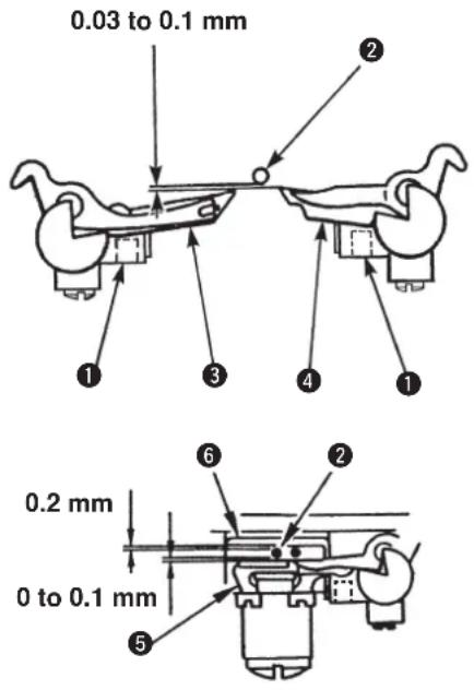

The standard adjustment value of the clearance between the needle and the looper is 0.03 to 0.1 mm.
Loosen looper setscrew ① and adjust the clearance between needle ② and left looper ③, and between the needle and right looper ④. Then fix the loopers in place.
Dimension for reference purpose

Clearance between the needle and needle guard ⑤ : 0 to 0.1 mm
Clearance between the needle and holder ⑥ : 0.2 mm

Be sure to adjust the clearance whenever the needle size is changed.
(4) Adjusting the needle guard

DANGER :
Be sure carry out the work while observing the following in order to protect against pinching of hands, fingers and arms between the sewing machine and the bottom cover, which can result in serious injury, when you raise the sewing machine from its home position.
- Be sure to lock the hinge stopper to firmly secure the sewing machine in its raised position.
* Read and check how to rise/return the sewing machine described on p.3 to p.5.
WARNING :
Turn OFF the power before starting the work so as to prevent accidents caused by abrupt start of the sewing machine.
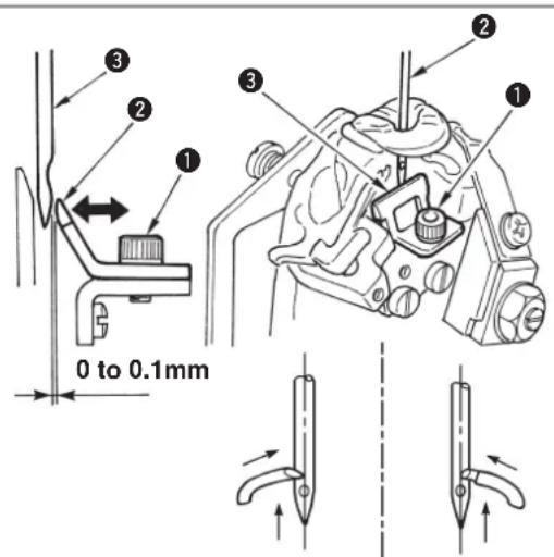
1) Loosen setscrew ①.
2) Set the clearance between needle ② and needle guard ③ to 0 to 0.1 mm.
3) Tighten setscrew 1.
4) Check the position both at the time of needle inside and of needle outside.

Be sure to adjust the needle guard when the needle size is changed or when the adjustment of needle and looper is performed. Adjust the clearance when needle aligns with the looper balde point at the inside and outside respectively.
(5) Installation positions of the spreaders and the timing to open/close the spreaders

DANGER :
Be sure carry out the work while observing the following in order to protect against pinching of hands, fingers and arms between the sewing machine and the bottom cover, which can result in serious injury, when you raise the sewing machine from its home position.
- Be sure to lock the hinge stopper to firmly secure the sewing machine in its raised position.
* Read and check how to rise/return the sewing machine described on p.3 to p.5.
WARNING :
Turn OFF the power before starting the work so as to prevent accidents caused by abrupt start of the sewing machine.
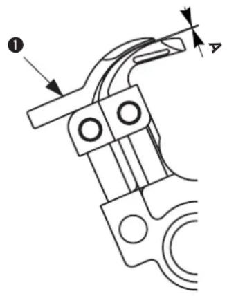
natural_image
Technical line drawing of a mechanical component with no visible text or symbols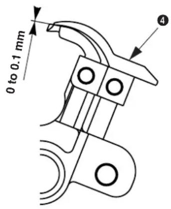
● Position of left spreader ① height
The clearance A provided between left spreader piece of looper thread to be used.
① and the top surface of the left looper is as small as a
● Position of right spreader ④ height
The clearance provided between right spreader
④ and the top surface of the right looper is 0 to 0.1 mm.

- Adjust the clearance by reforming the spreader. Place the top end of the spreader on the wooden board or the like and gradually bend it by hand since using pliers or the like will cause the spreader to break.
- If the clearance provided between the spreader and the looper is excessively small or large, stitch skipping or needle breakage will result.
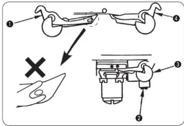
● Installation position of the left spreader
The center of the forked section at the top of left spreader ① is aligned with the center of the looper thread hole in the left looper.
Loosen setscrew ② in the spreader stopper and adjust the position of spreader stopper ③. Then fix the spreader in place. (Make the same adjustment for both left/right spreaders.)

When the top end of the left spreader in terms of the left looper protrudes, stitch skipping will result.
● Installation position of the right spreader
The ridge line (on the needle side) on right spreader 4 is aligned with the ridge line (on the needle side) on the right looper.
● Timing to open/close the spreaders

Adjust so that the spreaders open/close equally on the left and right without interfering with the needle. When the stitch bite width is excessively small and eyelet stitches are irregular, adjust the timing to X2 < X1.

Make sure of the width or the timing when the stitch bite width is changed or after performing the looper timing adjustment.
Loosen setscrews ⑥ in spreader driving shaft guide ⑤ and move the guide up and down to make the adjustment. Then fix the guide.

As the spreader driving shaft guide moves upward, the opening amount of the right spreader will be greater than that of the left spreader. (X1 > X2)
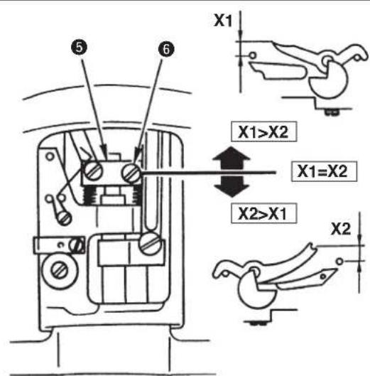
(6) Position of the presser foot and the needle entry point

WARNING :
Turn OFF the power before starting the work so as to prevent accidents caused by abrupt start of the sewing machine.
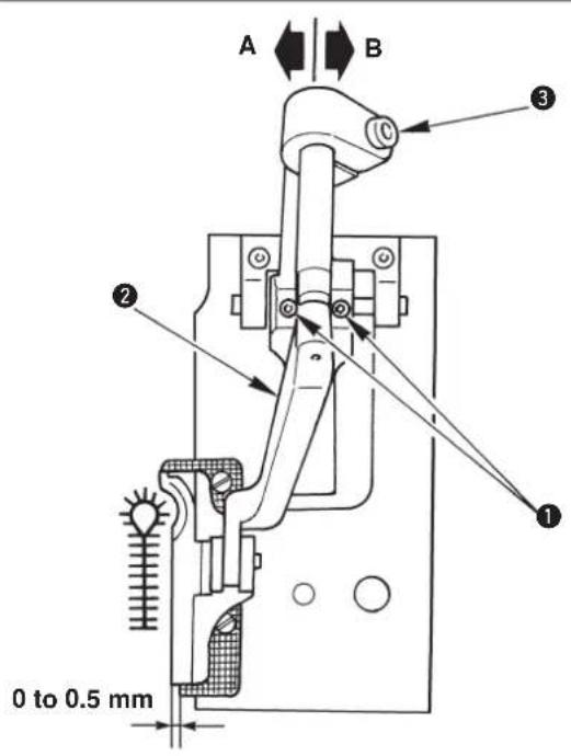

Adjust the clearance between the presser foot and the holding plate to 0 to 0.5 mm.
Loosen two setscrews ① in the presser arm base and the adjust the clearance. Then fix the presser arm in place.

Moving presser arm ② in the direction A will reduce the clearance between the presser foot and the outside needle entry point.
* The front or rear inclination can be adjusted with presser arm setscrew ③.
(7) Adjusting the knife dropping position

WARNING :
Turn OFF the power before starting the work so as to prevent accidents caused by abrupt start of the sewing machine.
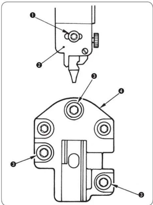
● Upper knife type
Loosen setscrew
① in the cloth cutting knife last cloth cutting knife installing r right. Then fix the base.
installing base, adjust cloth cutting knife installing base ② to the left or right. Then fix the base.
● Lower knife type
Loosen setscrews
③ in the knife base and adjust the left or right. Then fix the knife
(8) Installing position of the needle thread trimming knife

WARNING :
Turn OFF the power before starting the work so as to prevent accidents caused by abrupt start of the sewing machine.
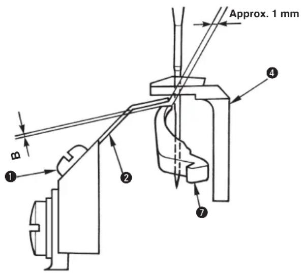
1.2 to 1.5 mm
Approx. 3.2 mm
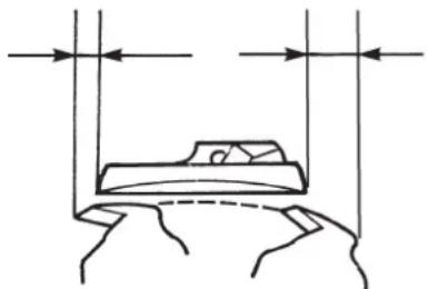
natural_image
Simple line drawing of a bed with two vertical supports and horizontal arrows indicating measurement or alignment (no text or symbols)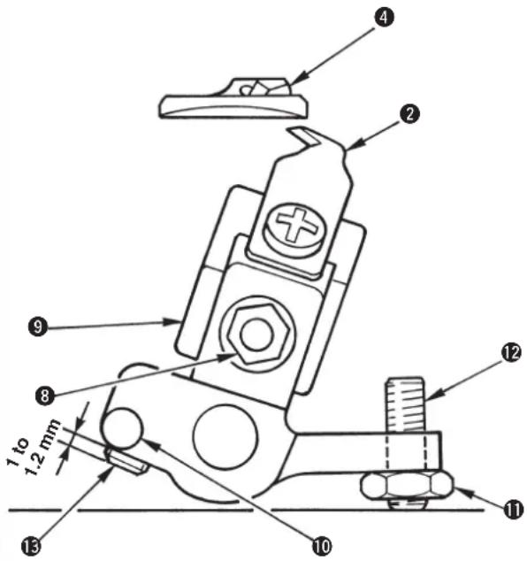
(Reference)
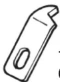
14050009
(Right blade type)
■ S and R type (long thread trimming)
1) The clearance between needle thread trimming knife J ② and the needle is approximately 1 mm. Loosen setscrew ① and move needle thread trimming knife J ② to adjust the clearance.
2) Loosen nut ⑧, move needle thread trimming adjusting base ⑨ up and down, and adjust clearance "B" between the needle thread trimming knife J and spreader, right ⑦ to 0.1 to 0.2 mm to obtain the height of needle thread trimming knife J ②.

When needle thread trimming knife J ② comes in contact with spreader, right ⑦, breakage of components will be caused.
3) The initial position of needle thread trimming knife J ② is the position where it protrudes 3.2 mm from throat plate ④. Loosen adjustment nut ⑪ and adjust the initial position with adjustment screw ⑫.
4) The operating position of needle thread trimming knife J ② is the position where needle thread trimming knife J ② comes out by 1.2 to 1.5 mm from throat plate ④ when needle thread trimming actuating arm ⑩ is moved counterclockwise and stopper B ⑬ of the needle thread trimming actuating arm comes in contact with the top surface of the looper bracket.
When the adjustment is necessary, loosen the stopper B ⑬ and set the protruding amount to 1 to 1.2 mm.

Stopper B 13 of the needle thread trimming actuating arm has double screws.

In case of using Part No. 14050009, refer to the Engineer's Manual.
■ T type (short thread trimming without gimp)
Perform the adjustment of the aforementioned steps 1) to 4) with the left looper (eye looper) instead of right spreader 7.
When the clearance of 1 mm provided between the top end of needle thread trimming knife J ② and the needle (edge of the left looper) is smaller, the knife cuts even the looper thread and the looper thread cannot be retained. When such phenomenon as this occurs, adjust the clearance of 1 mm to rather large.
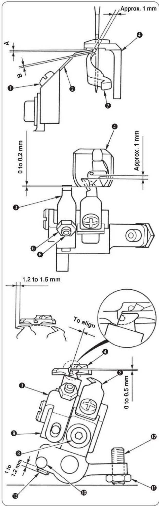
■ J and C type (short thread trimming)
1) The clearance between needle thread trimming knife J ② and the needle is approximately 1 mm.
Loosen setscrew ① and move needle thread trimming knife J ② to adjust the clearance.
2) The overlapping amount between looper thread presser ③ and the top end section of throat plate ④ is 0 to 0.2 mm, and adjust so that no clearance is provided between them.
Loosen adjustment nut ⑤ and adjust the position of the top end of looper thread presse ③ with adjustment screw ⑥.
3) The height of needle thread trimming knife J ② is determined by the adjustment value of looper thread presser ③. After the adjustment of step 4) below, confirm that clearance A between the looper thread presser and throat plate ④ and that B between the looper thread presser and right spreader ⑦ are securely obtained.
4) The height of looper thread presser ③ is the position where the top end is lowered by 0 to 0.5 mm from the flat face of throat plate ④.
Loosen setscrew ⑧ and move needle thread trimming knife adjustment base ⑨ up or down to adjust the height of the top end of looper thread presser ③.

When needle thread trimming knife J ② comes in contact with throat plate ④ and spreader, right ⑦, breakage of components will be caused. Make sure of the clearances "A" and "B".
5) The initial position of needle thread trimming knife J ② and looper thread presser ③ is the position where the left corner of the top end of looper thread presser ③ is aligned with the right corner of the slot of throat plate ④.
Loosen adjustment nut ⑪ and adjust the initial position with adjustment screw ⑫.
6) The operating position of needle thread trimming knife J ② is the position where needle thread trimming knife J ② comes out by 1.2 to 1.5 mm from throat plate ④ when needle thread trimming actuating arm ⑩ is moved counterclockwise and stopper B ⑬ of the needle thread trimming actuating arm comes in contact with the top surface of the looper bracket.
When the adjustment is necessary, remove needle thread trimming adjusting base ⑨ once with setscrew ⑧ and adjust the protruding amount of stopper B ⑬ to 1 to 1.2 mm.

Stopper B ⑬ of the needle thread trimming actuating arm has double screws.
(9) Adjusting the looper thread trimming

WARNING :
Turn OFF the power before starting the work so as to prevent accidents caused by abrupt start of the sewing machine.
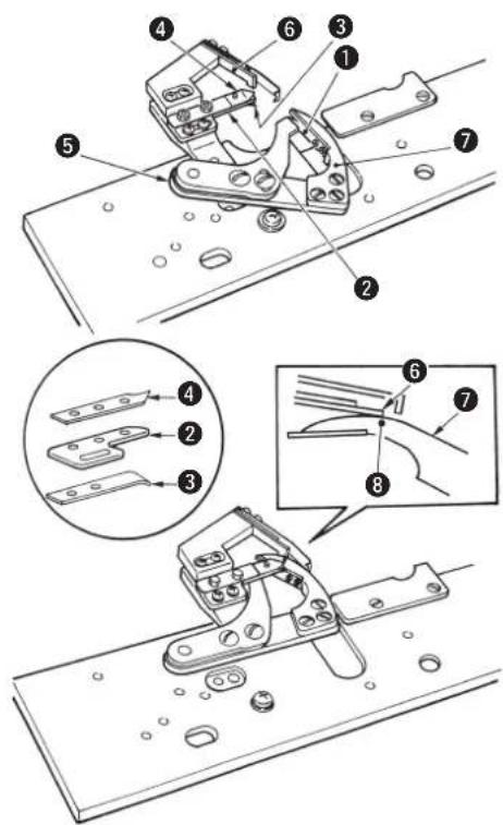
■ S and R type (long thread trimming)

Looper thread and gimp trimming is operated at the position of the feed base origin and the presser goes up after the trimming.
1) Looper thread and gimp have been adjusted so that they are separated upward and downward by thread handling plate ①.
2) Looper thread is precisely held between looper thread clamp fixing plate ② and looper thread clamp ③ of the plate spring and gimp is precisely held between looper thread clamp fixing plate ② and gimp clamp ④ of the plate spring.
3) Adjustment has been performed so that the top end of counter knife ⑥ is aligned with engraved dot ⑧ of moving knife ⑦ when the stroke of looper thread trimming actuating arm ⑤ is maximum.

When the cut end (thread waste) of looper thread or gimp is clamped with looper thread clamp ③ or gimp clamp ④, clamp failure occurs. As a result, stitch skipping at the sewing start or defective stitches will occur. So, remove the thread waste.
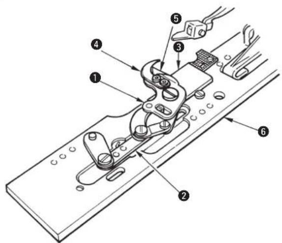
■ J and C type (short thread trimming)

When the feed base is manually moved to the rear until it will go no further, upper knife lower cover ⑤ rides on the cloth cutting knife and remove presser unit ⑥.

Looper thread and gimp trimming is operated at the position of the feed base origin after the presser has been lifted.
1) Looper thread and gimp have been adjusted so that they are separated from the cloth by thread handling plate ④.
2) Driving link ② is actuated and lower knife ③ and upper knife ① engage with each other to perform thread trimming.
3) Upper knife lower cover ⑤ controls the variation of the remaining looper thread when looper thread comes in contact with the blade of the moving knife.

At the time of delivery or when the following presser sets are used, use the cloth cutting knife with the same size as that supplied with the machine. If a cloth cutting knife with different size is used, the knife unit breakage or the like will be caused.
In the state of the standard delivery of J type, the presser of M set is installed

ewing length can be changed as shown below by installing the optional presser set and moving the installing position of the knife unit only.
S set : 16 to 26 mm
M set : 24 to 34 mm
L set : 32 to 42 mm
Fig. 1
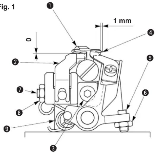
Fig. 2
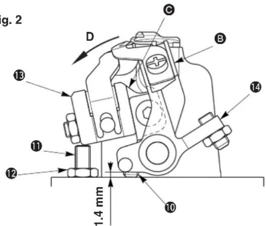
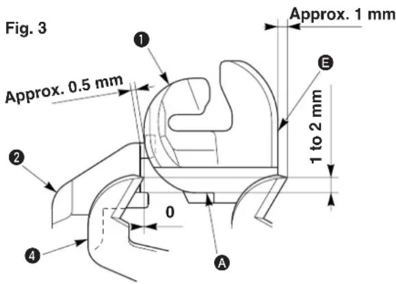
Fig. 4
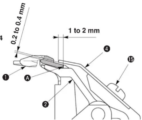

T type (short thread trimming without gimp)
Adjusting the looper thread presser
1) Loosen setscrew 3.
2) Fully press downward throat plat i and install it. (Fig. 1)
3) Lightly press upward the looper thread presser so that a clearance is not provided between looper thread presser ② and the bottom surface of throat plate ①. Then tighten setscrew ③.
4) Loosen nut ⑧ and tighten adjusting screw ⑦ until the top end of the screw comes in contact with looper bracket ⑨.
5) Further, turn it by 1/4 turn and fix it with nut 8.
6) Loosen nut 12. (Fig. 2)
7) Press section of installing base in the direction of arrow mark D with finger, tighten adjusting scn so that the thread guide section of looper thread presser ① protrudes from throat plat by approximately 0.5 mm and fix the screw with nu2. (Fig. 2 and Fig. 3)

- When the clearance provided between throat plate ① and the looper thread presser is smaller than the specified value, the looper thread holding force is insufficient. As a result, stitch skipping at the start of sewing or defective roll-in of thread will be caused.
- When the loop er th read presser is excessively pressed to throat plate ①, component breakage or excessive tightness of stitches at the start of sewing will result.
Adjusting the looper thread trimming knife
8) Loosen setscrew 15 and adjust so that the top end of looper thread trimming knife 4 is located at the position of 1 to 2 mm from section A of throat plate 1 and that a clearance of 0.2 to 0.4 mm is provided between the bottom surface of the looper thread trimming knife and throat plate 1. (Fig. 3 and Fig. 4)
9) Loosen nut 6.
10) Tighten adjusting screw 5 so that the blade point of looper thread trimming knife 4 protrudes from end plane E of throat plate 1 by approximately 1 mm. Then fix it with nut 6. (Fig. 1 and Fig. 3)
11) Press section B of knife installing base 14 in the direction of arrow mark D with finger, tighten adjusting screw 10 (double thread screw) so that the top end of looper thread trimming knife 4 aligns with the end plane of throat plate 1. Then fix the base. The standard of the protruding amount of adjusting screw 10 is 1.4 mm. (Fig. 2 and Fig. 3)

- When the lateral position of looper thread trimming knife ④ is not obtained, thread trimming failure or interference with the presser will result.
- When looper thread trimming knife ④ is positioned too high, looper thread trimming failure or cut-off of stitches will result.

When the looper thread is not retained immediately after threading or the like, perform sewing after retaining the looper thread at section A of throat plate ① with looper thread presse ②.
(10) Cleaning

DANGER :
Be sure carry out the work while observing the following in order to protect against pinching of hands, fingers and arms between the sewing machine and the bottom cover, which can result in serious injury, when you raise the sewing machine from its home position.
- Be sure to lock the hinge stopper to firmly secure the sewing machine in its raised position. * Read and check how to rise/return the sewing machine described on p.3 to p.5.
WARNING :
Turn OFF the power before starting the work so as to prevent accidents caused by abrupt start of the sewing machine.
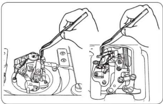
natural_image
Technical line drawing showing hands using a tool to adjust or install mechanical components (no text or symbols present)Be sure to remove thread waste or dust collected since the thread waste may be sewn together with the sewing product.

For J/C types, thread waste occurs every time of sewing since the short thread remaining function works.
Perform cleaning of the machine once in half a day to a day.
(11) Draining

WARNING :
Turn OFF the power before starting the work so as to prevent accidents caused by abrupt start of the sewing machine.
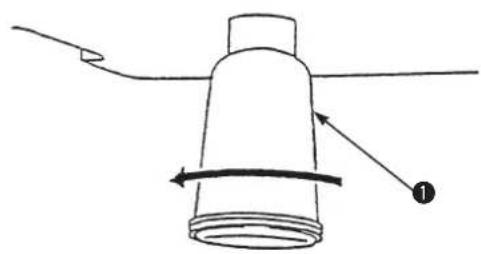
natural_image
Simple line drawing of a cylindrical object with a curved arrow indicating rotation, no text or symbols presentWhen polyethylene oiler ① under the bottom cover becomes filled with oil, remove it and drain the oil.
(12) Checking the fan filter

WARNING :
Turn OFF the power before starting the work so as to prevent accidents caused by abrupt start of the sewing machine.
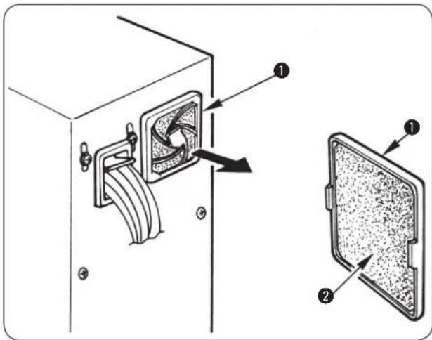

Clean filter ② of the control box fan once every week.
1) Pull screen kit ① in the direction of the arrow to remove it.
2) Wash filter ② under running water.
3) Reinstall filter ② and screen kit ① in place.

WARNING :
Be sure to fully dry and install the filter after washing it.
(13) Replacing the fuse

WARNING :
To prevent electric shock or personal injury caused by abrupt start of the sewing machine, turn OFF the power and remove the cover after an elapse of 5 minutes or more. To prevent personal injury, be sure to turn OFF the power and replace the fuse with one with same capacity after removing the cause of blown-out of the fuse when the fuse has blown out.
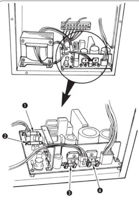
1) Turn OFF the power with the power switch after confirming that the sewing machine has stopped.
2) Draw the power cord from the power receptacle after confirming that the power switch is turned OFF. Then wait for more than 5 minutes.
3) Remove six screws fixing the rear cover of the control box. Then slowly open the rear cover.
4) Grasp the glass section of the fuse to be replaced and remove it.
5) Use the fuse with the specified capacity.

The machine uses the following four fuses.
① and ② For servo-motor power protection
15 A each
(Standard melting fuse pcb direct-installing type)
③ For control power and active tension protection
10 A (Time-lag fuse)
④ For stepping motor protection
6.3 A (Time-lag fuse)
(14) Standard of replacing time of the gas spring

DANGER :
There is a risk of pinching of hand, fingers and arms to cause a serious injury if you raise it when the gas spring does not function, since the sewing machine is very heavy in weight. In order to prevent an accident, be sure to replace the gas spring with a new one before it is too late according to the standard of replacing time (as described below).
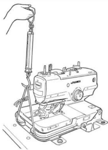
natural_image
Line drawing of a sewing machine with a hand adjusting the hook (no text or symbols)1) Gas spring is one of the consumables. Gas inside the gas spring will be gone naturally even when the frequency of use is low and the spring cannot display the thrust to secure the safety. In case a force of 156N or more is necessary when passing strings through the front end of machine bed and lifting the sewing machine as shown in the left-hand figure, quickly replace the spring with JUKI genuine gas spring (Part No.: 40061247).

Gas spring is a component that can be used with ease. However, there is a flaw on the rod section or a section that is weak in the side load when the gas spring is fully stretched. Be very careful when performing maintenance or cleaning of the sewing machine.
(15) Replacing the gas spring

DANGER :
Be sure carry out the work while observing the following in order to protect against pinching of hands, fingers and arms between the sewing machine and the bottom cover, which can result in serious injury, when you raise or return the sewing machine from or back to its home position.
- Be sure to hold the rib on the bed periphery when holding the sewing machine.
- Be sure to lock the hinge stopper to firmly secure the sewing machine in its raised position.
WARNING :
Turn OFF the power before starting the work so as to prevent accidents caused by abrupt start of the sewing machine.
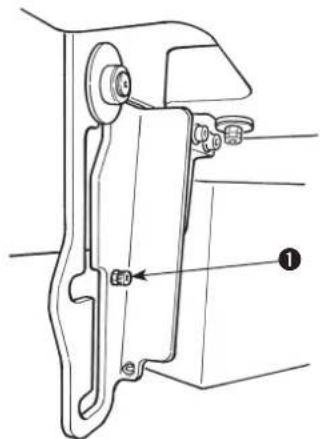
1) Loosen and remove stopper screw ①.
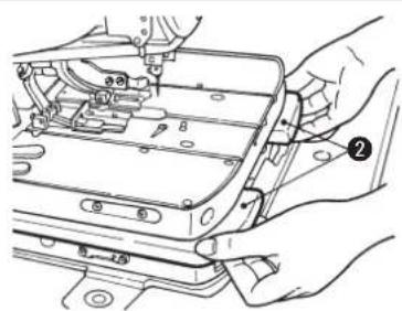
2) Hold with your both hands periphery ribs located on the front side of machine bed, slowly lift the sewing machine, and stop it at the lock position of the intermediate section.
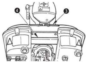

Do not hold feed base ③ and feed guide shaft fixing base ④.

3) Further, support periphery ribs ② of the machine bed with your left hand, hold grip ⑤ of the hinge stopper section with your right hand, release the lock, and slowly lift the sewing machine. When the sewing machine starts lifting, set free the hinge stopper section held with your right hand and support the periphery ribs with your both hands.
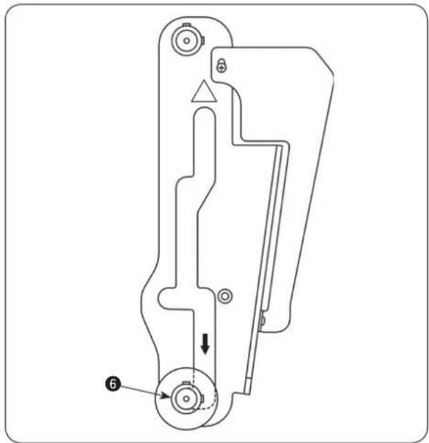
natural_image
Technical line drawing of a mechanical component with no visible text or symbols4) Further, lift the sewing machine and adjust so that support shaft ⑥ moves to the last lock position of the hinge stopper.
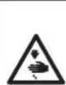
DANGER :
If the hinge stopper is not locked, the sewing machine can drop to pinch hands, fingers and arms leading to a serious injury. Make sure that the hinge stopper is locked with support shaft ⑥.
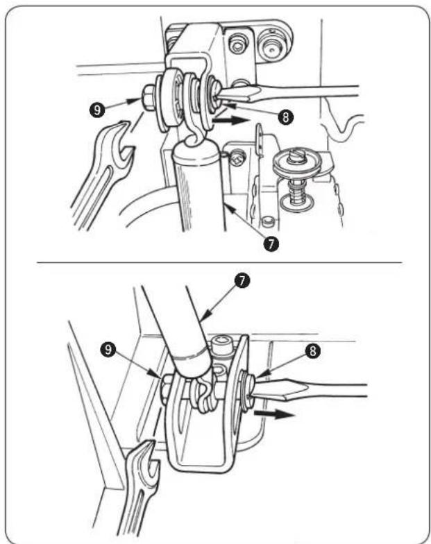
5) Remove nut ⑨ from fulcrum shaft ⑧ and draw out fulcrum shaft ③ after confirming that the force of gas spring ⑦ does not work to the sewing machine.
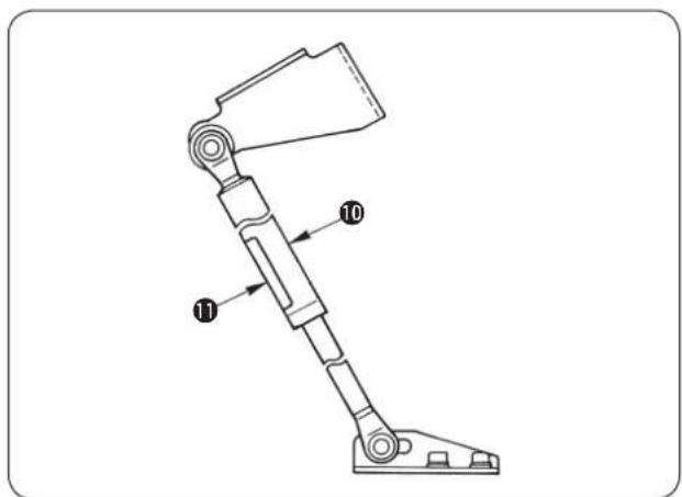
6) Install new gas spring ^10 so that yellow caution seal ^11 comes to the front side same as before.
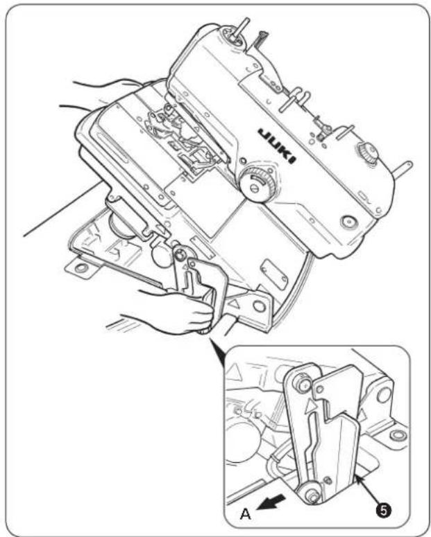
7) When assembling is completed, return the sewing machine to its home position. When returning the sewing machine, support periphery ribs ② of the machine bed with your left hand, hold grip ⑤ of the hinge stopper section with your right hand, pull it to this side (direction A) to release the lock and slowly lower the sewing machine after confirming that there is no tool such as screwdriver and the like in the bottom cover.
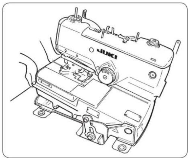
natural_image
Line drawing of a sewing machine with hands operating it (no text or symbols present)8) Take your right hand off from the hinge stopper section, support periphery ribs ② of machine bed with your both hands and further lower the sewing machine.
DANGER :

- Do not lower the sewing machine while keeping pulling the hinge stopper in direction A, in order to prevent pining of fingers, hands and arms under the sewing machine leading to a serious injury.
- Do not hold feed base ③ and feed guide shaft fixing base ④.
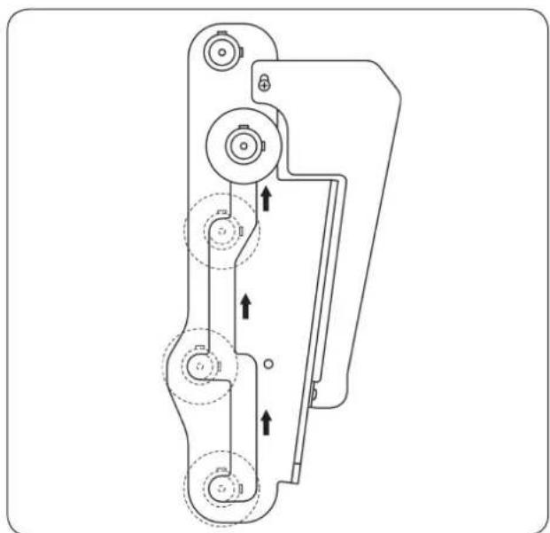
natural_image
Technical line drawing of a mechanical device with multiple circular components and directional arrows indicating motion (no text or symbols)9) The lock works two times for the safety while the sewing machine is lowered. Every time, support the periphery ribs of machine bed with your left hand, hold the grip of hinge stopper section with your right hand, release the lock, and slowly lower the sewing machine.

DANGER :
Take care to prevent pinching of hands and fingers between the sewing machine and the bottom cover. In particular, never lower the sewing machine holding parts other than the bed rib with two or more workers, since doing so can cause pinching of hands, fingers and arms leading to a serious injury.
10) When the sewing machine is completely lowered, attach stopper screw ① that has been removed before.
12. EXCHANGING GAGUE PARTS AND OPTIONAL
(1) Changing the thread trimming method
DIP switch
Thread trimming type is selected with DIP switch 1 and 2 located at the rear of the machine head.

It is necessary to separately set the memory switch (machine model setting) in case of the change of type such as S J and the like.
1) S and R type (long thread trimming)
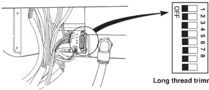
| DIP-SW | Type | |
| 1 | 2 | Long thread trimming |
| OFF | OFF | |

Do not change DIP-SW for the long thread trimming type.
2) J and C type (short thread trimming)
| DIP-SW | Presser type | |
| 1 2 | ||
| ON OFF S | ||
| OFF ON M | ||
| ON ON L | ||
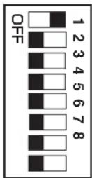
Short thread trimming S (C standard)
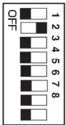
Short thread trimming M (J standard)
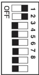
Short thread trimming L

Simultaneously change DIP-SW when changing the presser set for J and C types. When changing the presser set, the pattern used before the change cannot be used.
3) T type (short thread trimming without gimp) – for slacks
| DIP-SW | Type | ||
| 1 | 2 | 3 | Short thread trimming without gimp |
| OFF | OFF | ON | |
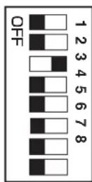

Do not change DIP-SW for the short thread trimming without gimp type.
(2) Exchanging gauge parts
(The mark in [ ] parentheses shows the standard equipment for each type.)
Throat plate
| Throat plate A Name of part (Standard) | Throat plate B Th [S, R] | roat plate C Throat (For semi-wide width) | plate D Throat plate (For wide width) (F) | TE (For narrow width) (Standard) | [T] | ||
| Needle size | #90 to #110 #100 to #110 | ||||||
| Gimp position W | 1.3 mm 1.8 mm | 2.4 mm | 1.1 mm | Without | |||
| Shape | 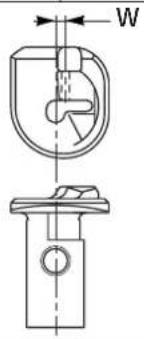 | 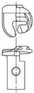 | |||||
| Part No. | 32042715 320(32042707) | 42913(32042905) | 320 | 43010 32043218(32043002) | 32043713(32043200) | ||
| Type | For S and R types | For T type | |||||
| Name of part(Standard) | Throat plate JA[J] | Throat plate JB(For semi-wide width) | Throat plate JC(For wide width) (F) | Throat plate JDor narrow width) | Throat plate JE(Standard) [C] | Throat plate JF(For narrow width) |
| Needle size | #120 to #130 | #90 to #110 | #90 to #100 | #110 to #120 | #90 to #100 | |
| Gimp position W | 1.3 mm 1.8 mm | 2.4 mm 1.1 mm | 1.3 mm 1.3 mm | |||
| Shape | 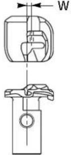 | |||||
| Part No. | 32043424 32032043416)(32043408) | 42830(32042822)(32042814) | 43135 32043622(32043127)(32043119) | 32043523 32043325(32043614)(32043606) | (32043515)(32043507) | (32043317)(32043309) |
| Type | For J and C types | |||||
* Part Nos. with ( ) parentheses can be used.
Presser set
| Name of part | Eyelet buttonhole compensating presser S set | Eyelet buttonhole compensating presser M set | Eyelet buttonhole compensating presser L set * | ||
| Shape | 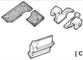 | 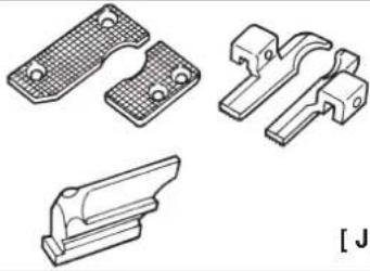 | 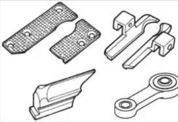 | ||
| Part No. | 32028458 | 32028854 | 32029050 | ||
| For J and C types | |||||
* When L set is used, cloth cutting plate A, part No. 32068702 is separately necessary.
Presser set
| Name of part | Longitudinal hole presser set |
| Shape | 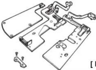 |
| Part No. | 32031064 |
| For S and R types |
Presser foot
| Presser foot (left) | Name of part | For eyelet buttonhole 40 mm | For eyelet buttonhole 32 mm | For eyelet buttonhole 22 mm | For decorative buttonhole 40 mm | Eyelet buttonhole compensating foot H 40 mm | Eyelet buttonhole compensating foot M 40 mm | Eyelet buttonhole compensating foot S 40 mm |
| Shape | 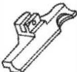 | 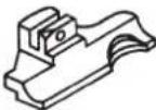 | 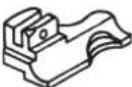 | 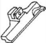 | (For L type) | (For M type) | (For S type) | |
| [S,R] | 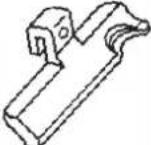 | 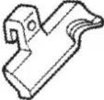 | 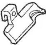 | |||||
| Part No. | 14010102 | 14059604 | 14059802 | 14013908 | 14058903 | 32028706 | 32028300 |
| Presser foot (right) | Name of part | For eyelet buttonhole 40 mm | For eyelet buttonhole 32 mm | For eyelet buttonhole 22 mm | For decorative buttonhole 40 mm | Eyelet buttonhole compensating foot H 40 mm | Eyelet buttonhole compensating foot M 40 mm | Eyelet buttonhole compensating foot S 40 mm |
| Shape | 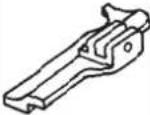 | 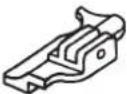 | 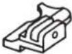 | 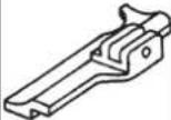 | (For L type) | (For M type) | (For S type) | |
| [S,R] | 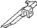 | 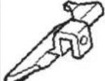 | 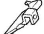 | |||||
| Part No. | 14010003 | 14059505 | 14059703 | 14013909 | 14058804 | 32028607 | 32028201 |
| Presser foot (left) | Name of part | Compensating foot for eyelet buttonhole 32 mm | Compensating foot for eyelet buttonhole 22 mm |
| Shape | 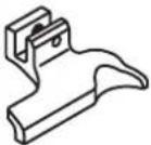 | 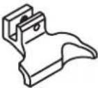 | |
| Part No. | 40035239 | 40039844 |
| Presser foot (right) | Name of part | Compensating foot for eyelet buttonhole 32 mm | Compensating foot for eyelet buttonhole 22 mm |
| Shape | 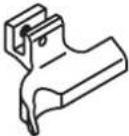 | 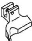 | |
| Part No. | 40035238 | 40039843 |
Presser holding plate
| Name of part | Eyelet buttonhole presser holding plate, left | Eyelet buttonhole presser holding plate, right | Eyelet buttonhole presser holding plate, left | Eyelet buttonhole presser holding plate, right | Eyelet buttonhole presser holding plate, left | Eyelet buttonhole presser holding plate, right |
| Shape of hole | Eyelet buttonhole Decorat | ive buttonhole Eyelet buttonhole | ||||
| Stitch length | 10 to 38 10 to 34 | |||||
| Shape |  |  |  |  |  |  |
| Part No. | 32027104 | 32027005 320 | 29506 32029407 14 | 011506 14011407 | ||
| Type For S and R types For T type | ||||||
| Name of part | Eyelet buttonhole presser holding plate, left | Eyelet buttonhole presser holding plate, right | Eyelet buttonhole presser holding plate, left | Eyelet buttonhole presser holding plate, right | Eyelet buttonhole presser holding plate, left | Eyelet buttonhole presser holding plate, right |
| Shape of hole | Eyelet buttonhole | |||||
| Stitch length | S: 16 to 24 [C] | M: 24 to 32 [J] | L: 32 to 40 | |||
| Shape |  |  |  |  |  |  |
| Part No. | 32028516(32028505) | 32028409 | 32028912(32028904) | 32028805 32029100 32029001 | ||
| Type For J and C types | ||||||
* Part Nos. with ( ) parentheses can be used.
Cloth cutting knife
| For eyelet buttonhole | For decorative buttonhole | |||||
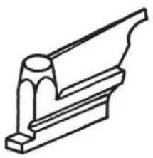 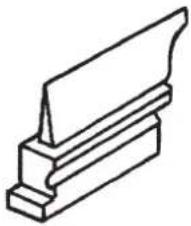 | ||||||
| For eyelet buttonhole | Standard equipment | Part No. X | Y | Remarks | ||
| R 14041206 | 2.9 4.4 L | Long thread trimming, short thread trimming, sewing length L | ||||
| T 32063604 | 2.9 4.4 S | Short thread trimming, sewing length S | ||||
| 32063703 2 | 9 4.4 Sho | t thread trimming, sewing length M | ||||
| 32063802 | 2.1 3.2 | Long thread trimming, short thread trimming, sewing length L | ||||
| 32063901 | 2.1 3.2 | Short thread trimming, sewing length S | ||||
| 32064008 | 2.1 3.2 | Short thread trimming, sewing length M | ||||
| 32064107 | 3.2 5.4 | Long thread trimming, short thread trimming, sewing llengthL | ||||
| 32064206 | 3.2 5.4 | Short thread trimming, sewing length S | ||||
| 32064305 | 3.2 5.4 | Short thread trimming, sewing length M | ||||
| 32066904 | 2.7 5.1 | Long thread trimming, short thread trimming, sewing length L | ||||
| For decorative buttonhole | S, R | 14041404 | 0 | 0 | Long thread trimming, short thread trimming, sewing length L | |
| 32065302 | 0 | 0 | Short thread trimming, sewing length S | |||
| 32065401 | 0 | 0 | Short thread trimming, sewing length M | |||
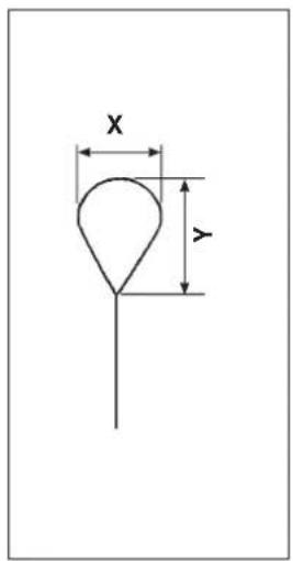
Looper (left) · Spreader (left)
| Looper (left) | Spreader (left) | ||||
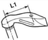 | 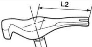 | ||||
| Applicable stitch bite width | Standard equipment | L1 | Part No. | L2 | Part No. |
| 2.0 to 3.2 mm | S, R, J, C, T | 6 | 32040800 | 11 | 32040917 |
| * 2.6 to 4.0 mm | 7 | 14030902 | 11.6 | 14031116 | |
* Width of 2.6 to 4.0 mm is optional.
Knife holder
(The mark in [ ] parentheses shows the standard equipment for each type.)
| Name of part | For eyelet buttonhole | |||
| Shape | ![JUKI MEB3200 - (The mark in [ ] parentheses shows the standard equipment for each type.) - 1](/content/2026/04/604076/images/5ddbe61c33f733276cc46199f57f538ca9c8153da5fe390c8458c3023a7b921e.jpg) | |||
| Size (mm) | Part No. | Size (mm) | Part No. | |
| 38 | [S,R] 32062101 | 22 | [S,R,J,C] 32062903 | |
| 36 | 32062200 | 20 | [S,R] 32063000 | |
| 34 | 32062309 | 18 | [C,T] 32063109 | |
| 32 | 32062408 | 16 | [S,R] 32063208 | |
| 30 | 32062507 | 14 | 32063307 | |
| 28 | 32062606 | 12 | 32063406 | |
| 26 | 32062705 | 10 | 32063505 | |
| 24 | 32062804 | |||
| Name of part | For decorative buttonhole | |||
| Shape | ![JUKI MEB3200 - (The mark in [ ] parentheses shows the standard equipment for each type.) - 2](/content/2026/04/604076/images/ed4e3a3df9ff98222cbb8d897c07ae0bb1b24a9ba4277994822b40fe51255e35.jpg) | |||
| Size (mm) | Part No. | Size (mm) | Part No. | |
| 38 | 14042501 | 22 | [S,R] 14042907 | |
| 36 | 32064404 | 0 | 32064909 | |
| 34 | 32064503 | 18 | 32065005 | |
| 32 | 14042600 | 16 | 14043109 | |
| 30 | 32064602 | 14 | 32065104 | |
| 28 | 32064701 | 12 | 32065203 | |
| 26 | 14042808 | 10 | 10443301 | |
| 24 | 32064800 | |||
Others
| Name of part | Foot pedal switch (asm.) | Pedal switch cable (asm.) | Hand switch (asm.) | |
| Shape and application | ![JUKI MEB3200 - (The mark in [ ] parentheses shows the standard equipment for each type.) - 3](/content/2026/04/604076/images/de79b377f3bf3a04c8dea571fb9a06ffd72c9800881a0c9d92ad9a132d849568.jpg) Operation of the sewing machine is performed by foot pedal. Operation of the sewing machine is performed by foot pedal. | ![JUKI MEB3200 - (The mark in [ ] parentheses shows the standard equipment for each type.) - 4](/content/2026/04/604076/images/3bea29473f103b7686554b0b4754637d0925eaea6218aff697e9edbd9ee89181.jpg) The cable is used to connect pedal switch (asm.). The cable is used to connect pedal switch (asm.). | ![JUKI MEB3200 - (The mark in [ ] parentheses shows the standard equipment for each type.) - 5](/content/2026/04/604076/images/beffbca833289cb0d525e6c8832f80ca5a93937925b7541b327bd1a71bf3387b.jpg) Button switch Button switch | |
| Part No. M85905130AA M90146200A0 32076655 | ||||
■ Installing the optional foot pedal
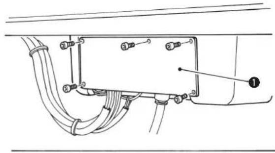
natural_image
Technical diagram of a mechanical or electrical component with labeled parts (no readable text or symbols)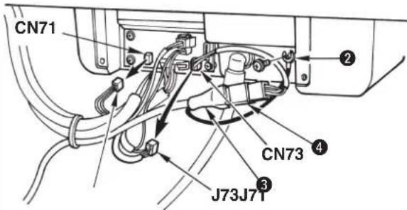

Hand switch is provided with S type and J type as standard. When using the optional foot switch, pedal switch cable (asm.) is necessary.
1) Loosen five setscrews and remove cover ① located at the rear of the machine head.
2) Remove CN71 and CN73 on the CONNECTOR circuit board.
3) Connect pedal switch (asm.) ③ and pedal switch cable (asm.) ④, and insert the cable to J73 on the CONNECTOR circuit board.
4) Connect ground wire ② of the pedal switch (asm.) ③ to the machine head.
5) Fix the cord with the cable clip band together with other cords.

Drive and start of the presser can be performed with the foot switch. Operation with the hand switch cannot be performed.
13. TROUBLES AND CORRECTIVE MEASURES IN SEWING
| Phenomenon | Cause | Corrective measure | Page |
| 1. Stitch skipping | The needle is bent. There is a scratch on the needle. The needle is incorrectly attached.Kind of needle is wrong.The clearance between the needle and the looper is too large.The clearance between the needle and the needle guard is too large or the needle and the needle guard come in excessive contact with each other.The clearance between the needle and the looper varies according to the turning angle (0°, 90° and 180°).Improper adjustment of the timing between the needle and the looperImproper adjustment of the timing to open/close the spreader The spreader comes in contact with the needle.Motion to open/close the spreader is not smooth.The clearance between the presser foot and the needle entry point is too large.Thread tension is not proper.The blade point of looper has worn out.Improper adjustment of the height of the needle barThe looper or the spreader not suitable for the stitch bite width is used.Improper adjustment of the clearance between the needle and the looperImproper adjustment of the timing to open/close the spreader The spreader comes in contact with the needle.The needle does not fit the kind of throat plate (needle size used).Thread which is difficult to make loops is used.(Hard-to-slide thread or the like)The needle is bent at the thick section of the material and stitch skipping occurs.In case of the cut-before knife, the inside needle is bent at the cutting section and stitch skipping occurs. | Check and replace the needle.Use DO x 558 needle.Adjust the clearance at the time of inside needle or outside needle.Check and adjust the clearance.Adjust the center of the needle.Adjust the timing with the stitch bite width used.Adjust the timing to open/close the spreader by the stitch bite width removede cloth waste from the spreader. Replace the spreader with a new one.Check the clearance and properly adjust it.Set the thread tension to the proper value.Correct the looper with oil-stone or the like, or replace it with a new one.Check and adjust the height of the needle bar.Replace the looper or the spreader with a new one suitable for the stitch bite width.Adjust the clearance at the time of inside needle or outside needle with the needle size used.Adjust the timing to open/close the spreader with the needle size used.Use the throat plate suitable for the needle.Decrease the needle thread tension. Lower the installing position of thread take-up thread guideDecrease the number of revolution of the sewing machine.Change the needle to a thicker one. Adjust the stitch base line offset.Re-set the cut space. | 994747-45494930,5016,40454545,644749w6116,3124,25923,33,37 |
| When changing needle sizeWhen kind of thread is affectedWhen sewing heavy-weight materials | The length of remaining needle thread at the start of sewing is too short.The left-hand spreader is installed incorrectly.The timing of the right-hand looper is too early.The clearance between the presser foot and the needle entry point is too large.The looper is bent. There are scratches on the looper.Feeding amount of the needle thread is insufficient.Looper thread clamp/looper thread presser is weak and the looper thread comes off at the start of sewing. | Decrease the needle thread tension at the time of thread trimming.Check the installing position and adjust it.Check the timing between the needle and the looper, and adjust it.Check the clearance and adjust it.Check the looper and replace it with a new one.Adjust the feeding amount of needle threadCheck and adjust the pressure. | 31,40484530,50453152 |
| Stitch skipping at the sewing start | The clearance between the presser foot and the needle entry point is too large.The cloth is flopping.Needle thread loop is too large and falls.As a result, it is not caught by the looper.Needle thread loop cannot be made.As a result, the looper cannot catch the thread | Check the clearance and adjust it properly.Decrease the sewing speed of eyelet section.Correct the presser foot or replace it with a new one.Lift the installing position of thread take-up thread guideDecrease the needle thread tension. Lower the installing position of thread take-up thread guide | 30,5025503116,31,40 |
| Seam splitting at the sewing end | The feeding amount of needle thread is insufficient.The timing of the right-hand looper is too late.The opening amount of the right-hand spreader is insufficient.The gimp is too hard. | Adjust the feeding amount of needle thread.Check and adjust the timing between the needle and the looper.Check and adjust the opening amount of the spreader.Replace the gimp. Check the thread path of gimp. | 31454912,32 |
| Needle thread breakage | The needle thread tension is too high.The needle comes in contact with the blade point of the looper.The thread paths in the needle, loopers, spreaders, throat plate, etc. have become worn out or contain scratches.The thread is too thick or too thin for the needle.There are scratches in the needle holeor needle slot. | Adjust the sewing conditions to obtain an appropriate thread tension.Check and adjust the clearance.Check and replace the respective parts.Replace the needle with a proper one.Check and replace the needle. | 16,31479,47,4899 |
| 6. Looper thread breakage | The looper thread tension is too high.The installing position of the left-hand spreader is incorrect.Refer to "5. Needle thread breakage" for details on other causes and corrective measures. | Adjust the sewing conditions to obtain an appropriate thread tension.Check and adjust the installing position. | 16. 4048 |
| 7. Needle breakage | The needle interferes with looper, spreader, etc.The needle comes in contact with the presser foot.The clearance between the needle and the looper varies according to the turning angle (0°, 90° and 180°).The clearance between the needle and the needle guard is too large or the needle and the needle guard come in excessive contact with each other.The height of the needle bar has been improperly adjusted.The needle does not fit the kind of throat plate (needle size used).Needle thread is depressed by the presser foot at the start of sewing. | Adjust the clearance between the looper and the needle properly. Adjust the timing to open/close the spreaders properly.Check and adjust the clearance.Adjust the center of the needle.Check and adjust the clearance.Check and adjust the height of the needle bar.Use the throat plate suitable for the needle.Increase the feeding amount of needle thread. | 47 to 4930 50-47456131 |
| 8. Stitches at the straight section of the but to nh ol e a re n ot uniform. | The left- and right-hand sewing pitches at the straight section are different from each other.The left- and right-hand positions at the straight section are different from each other.Stitches which should be parallel are slant. | Compensate the length by lengthwise compensation of left parallel section of the data compensation.Compensate the position by lengthwise compensation of left eyelet of the data compensation.Compensate the inclination by turning compensation of parallel section of the data compensation. | 353534 |
| 9. The left- and right-hand sides of the seam at the straight section of the buttonhole are not uniform. | The left- and right-hand side cloth opening amounts are not equal.Improper adjustment of the knife dropping positionThere is shrinkage of cloth by sewing or step difference between left- and right-hand sides of cloth. | Adjust so that the left- and right-hand side cloth opening amounts are equal.Check and adjust the knife dropping position.Individually set the left- and right-hand sides of cut space. | 3026. 33. 3723 37 |
| 10. The shape of the eyelet is deformed. | The seam is tilted.The cloth is deformed by the seam.Improper adjustment of the knife dropping positionThe cloth at eyelet section is flopping.The gimp is moved to the inside needle side. | Set the turning compensation/parallel section turning compensationSet the eyelet crosswise compensation/lengthwise compensationCheck and adjust the knife dropping position.Correct the presser foot or replace it with a new one.Replcae the throat plate with the optional one. | on. 343426. 33. 375061 |
| 11. The seam is cut by the cut-after knife. | The clearance between the cloth cutting knife and the needle is too small.Improper adjustment of the knife dropping positionThere is shrinkage of cloth by sewing or step difference between left- and right-hand sides of cloth. | Check the cut (eyelet) space and re-set it.Check the knife dropping position, and correct or adjust it.Individually set the left- and right-hand sides of cut space. | 22. 23,33. 34. 3726. 33. 3722. 37 |
| 12. Needle thread cannot be trimmed. | The needle thread trimming knife is dull.The stroke of the needle thread trimming knife is incorrect.The needle thread trimming knife does not catch needle thread.The last stitch has skipped.Installing position of the moving blade is incorrect. | Grind the knife or replace it with a new one.Check and adjust the stroke.Adjust the installing position (clearance between needle and knife) of the knife.Refer to "1. Stitch skipping".Check and adjust the moving blade and the thread separating position. | 40. 51. 5251. 5251. 52-51. 52 |
| 13. Looper thread cannot be trimmed.S/R types onlyJ/C types only | The knife is dull.The stroke of the moving blade is incorrect.Contact of the moving knife and the counter knife is improper.Installing position of the thread separating plate is incorrect.The knife pressure is insufficient. | Grind the knife or replace it with a new one.Check and adjust the stroke.Check and adjust the tilt of the counter knife.Check and adjust the moving blade and the thread separating position.Adjust the knife pressure. | 53535353 |
| 14. The cloth cannot be cut sharply. | Doubling the planes of the knife and the knife holder is incorrect.The knife is dull.Knife pressing amount (knife pressure) is insufficient.Chip has collected.Knife pressure is too high and the knife blade has broken. | Correct the surface of the knife holder with oil stone or the like.Grind the knife or replace it with a new one.Re-set the pressing amount (knife pressure).Remove the chip.Set proper knife pressure to each sewing product after replacing the knife. | 282627. 442626. 44 |
| 15. Breakage of looper/spreader | The clearance between the needle and the looper varies according to the angle (0°, 90° and 180°).The clearance between the needle and the needle guard is too large or the needle and the needle guard come in excessive contact with each other.The needle does not fit the kind of throat plate (needle size used). | Adjust the center of the needle.Check and adjust the clearance.Use the throat plate suitable for the needle. | -4761 |
14. MEMORY SWITCH
(1) Operating procedure
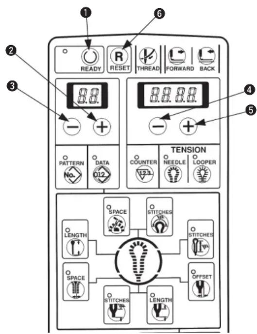

Pressing [READY ①key ①, turn ON the power and the mode becomes the memory switch mode. Then various data can be changed.
1) Select memory switch No. with [LEFT +key 2 or [LEFT +key 3.
2) Change the set value with [RIGHT ⊕] key ⑤ or [RIGHT ⊖] key ④.
3) Repeat the steps 1) to 2) when changing other set values.
4) After completion of setting, press [READY Ⓐ] key ⓚ to make the set value store in memory and the memory switch mode ends.
When [RESET ☐key ⑥ is pressed, the mode ends without storing the set value in memory. When turning OFF the power without pressing [READY ○] key ①, the setting is not stored in memory.
(2) Memory switch list
* H9 through L9 are displayed as well. However, they are the memory switches for the multicutting device. For the sewing machine not provided with the multicutting device, they are not effective even when the setting is changed.
| No. | Function | Description | Setting range | Setting unit | Initial value |
| 1 | Soft-start speed setting1st stitch (Inside needle → outside needle) | Limited speed at the sewing start of the sewing machine is set. From inside needle to outside needle of 1st stitch | 400 to 1,200 | 100sti/min | 600sti/min |
| 2 | Soft-start speed setting1st stitch (outside needle → inside needle) | Limited speed at the sewing start of the sewing machine is set. From outside needle to inside needle of 1st stitch | 400 to 2,200 | 100sti/min | 600sti/min |
| 3 | Soft-start speed setting2nd stitch (inside needle → outside needle) | Limited speed at the sewing start of the sewing machine is set. From inside needle to outside needle of 2nd stitch | 400 to 2,200 | 100sti/min | 600sti/min |
| 4 | Soft-start speed setting2nd stitch (outside needle → inside needle) | Limited speed at the sewing start of the sewing machine is set. From outside needle to inside needle of 2nd stitch | 400 to 2,200 | 100sti/min | 600sti/min |
| 5 | Soft-start speed setting3rd stitch (inside needle → outside needle) | Limited speed at the sewing start of the sewing machine is set. From inside needle to outside needle of 2nd stitch | 400 to 2,200 | 100sti/min | 600sti/min |
| 6 | Soft-start speed setting3rd stitch (outside needle → inside needle) | Limited speed at the sewing start of the sewing machine is set. From outside needle to inside needle of 3rd stitch | 400 to 2,200 | 100sti/min | 600sti/min |
| 7 | Needle thread tension setting at the time of thread trimming | Needle thread tension value at the time of thread trimming is set. | 0 to 255 | 1 | 0 |
| 8 | Looper thread tension setting at the time of thread trimming | Looper thread tension value at the time of thread trimming is set. | 0 to 255 | 1 | 0 |
| 9 | Needle thread tension setting at the time of machine-stop | Needle thread tension value at the time of machine-stop is set. | 0 to 255 | 1 | 60 |
| 10 | Looper thread tension setting at the time of machine-stop | Looper thread tension value at the time of machine-stop is set. | 0 to 255 | 1 | 0 |
| 11 | Set position selectionOrigin position/Front | Position of presser when setting cloth is selected.0 : Origin position1 : Front position (Position is set at No. = 29.) | 0 to 1 | - | 0 |
| 12 | Production counter selectionWithout/UP/DOWN | Operation of production counter is selected.0 : Without1 : UP counter (“ + 1” per sewing cycle)2 : DOWN counter (“ - 1” per sewing cycle) | 0 to 2 | - | 1 |
| 13 | Selection of starting when production counter is “0”Permitted/prohibited | Whether prohibiting starting at count value “0” when production counter is set to DOWN counter is selected.0 : Starting permitted even when production counter value is “0”1 : Starting prohibited when production counter valueis “0” | 0 to 1 | - | 1 |
| 14 | Start SwOne-touch starting selectionWith/without | Whether starting by start switch only is possible is selected.0: Presser comes down by presser switch, the machine is started by start switch1: Presser comes down by start switch and the machine starts (Presser switch is operative as well.) | 0 to 1 | - | 0 |
| 17 | Function key F1Data No. setting | Data Nos. which are aassigned to Function F1 key are set.(Initial value ... Knife position compensation) | 0 to 80 | - | 8 |
| 18 | Function F2 keyData No. setting | Data Nos. which are assigned to Function F2 key are set.(Initial value ... Copy destination No.) | 0 to 80 | - | 0 |
| 19 | With/without setting of thread tension compensation valueWith/without | Whether to set thread tension compensation value with NEEDLE/LOOPER key is selected.0: Without setting1: With setting | 0 to 1 | - | 0 |
| 20 | Selection of data setting prohibitionPermitted/prohibited | Whether to prohibit data setting is selected.0: Permitted1: Prohibited (Thread tension is possible.) | 0 to 1 | - | 0 |
| 22 | Looper thread trimming control | With/without looper thread trimming operation is set.0: Without1: With | 0 to 1 | - | 1 |
| 23 | Presser comes down when returning to set position | Whether presser returns to set position while it is lowered after sewing is selected.0: Presser goes up and returns to set position.1: Presser returns to set position while it is lowered and goes up. | 0 to 1 | - | 0 |
| 24 | Temporary stop of cut-after knife | Whether to automatically stop temporarily before operation of cut-after knife and to make the knife operate by start switch is selected.0: Normal operation1: Cut-after knife automatically stops temporarily before operation and is operated by start switch. | 0 to 1 | - | 0 |
| 26 | Straight bar and cloth open | Whether to perform sewing with the cloth open mechanism opened in case of the pattern in which straight bar is set.0: Normal operation1: Setting cloth with cloth open mechanism opened | 0 to 1 | - | 0 |
| 29 | Front set position | Position from the origin is set when "front" is selected with memory switch No. 11. | 0 to 64 | 1 mm | 22 |
| 40 | Knife pressing amount data setting accepted | Whether knife holder No. to which knife pressing amount has been set is set to pattern data is selected.0: Without (Knife holder No.0 fixed)1: With (Knife holer Nos.0 to 9 set) | 0 to 1 | - | 0 |
| 41 | Knife pressing amount (Knife holder No.1) | Knife pressing amount of knife holder No.1 | -100 to 300 | 1 | 0 |
| 42 | Knife pressing amount (Knife holder No.2) | Knife pressing amount of knife holder No.2 | -100 to 300 | 1 | 0 |
| 43 | Knife pressing amount (Knife holder No.3) | Knife pressing amount of knife holder No.3 | -100 to 300 | 1 | 0 |
| 44 | Knife pressing amount (Knife holder No.4) | Knife pressing amount of knife holder No.4 | -100 to 300 | 1 | 0 |
| 45 | Knife pressing amount (Knife holder No.5) | Knife pressing amount of knife holder No.5 | -100 to 300 | 1 | 0 |
| 46 | Knife pressing amount (Knife holder No.6) | Knife pressing amount of knife holder No.6 | -100 to 300 | 1 | 0 |
| 47 | Knife pressing amount (Knife holder No.7) | Knife pressing amount of knife holder No.7 | -100 to 300 | 1 | 0 |
| 48 | Knife pressing amount (Knife holder No.8) | Knife pressing amount of knife holder No.8 | -100 to 300 | 1 | 0 |
| 49 | Knife pressing amount (Knife holder No.9) | Knife pressing amount of knife holder No.9 | -100 to 300 | 1 | 0 |
| 50 | Knife pressing amount (Knife holder No.0) | Knife pressing amount of knife holder No.0 | -100 to 300 | 1 | 30 |
| 55 | Knife lower stop time | Period of time of stopping at the lower position of knife | 50 to 500 | 10 ms | 50 |
| 57 | Number of low speed pulses to lower knife motor | Cutting speed section at the time of cloth cutting (Down) | 0 to 300 | Pulse | 60 |
| 58 | Number of low speed pulses to lift knife motor | Cutting speed section at the time of cloth cutting (UP) | 80 to 300 | Pulse | 80 |
| 65 | With/without needle thread clamp | With/without needle thread clamp operation is set.0: Without1: With | 0 to 1 | - | 0/1 |
| 66 | Number of stitches to open needle thread clamp | Number of stitches at sewing start to open needle thread clamp is set. | 0 to 99 | 1 stitch | 5 |
| 69 | Needle thread clamp travelling amount | Setting of travelling amount by mm from end of sewing to close thread clamp | 0 to 50 | 1mm | 23/14 |
| B8 | Needle thread draw-in 2-stage operation | 0: 1-stage operation1: 2-stage operation | 0 to 1 | - | 0/1 |
| C0 | Lengthwise speed at the time of needle thread clamp | Lengthwise jump feed speed from end of sewing to needle thread clamp | 0 to 3,000 | 1 pulse/sec. | 1,000/1,500 |
- ERROR LIST
| No. | Description | How to reset |
| 1 | Sewing machine motor errorSewing machine motor doses not run or signal does not enter even when it is running. | Turn OFF the power. |
| 3 | Looper thread trimming knife return errorWhen the looper thread trimming knife has not returned at the time of operation of the sewing machine or operation of looper thread trimming | Remove the cause of error and press the RESET key. |
| 4 | Lengthwise direction stepping motor origin sensor errorWhen lengthwise direction origin sensor has not changed at the time of origin retrieval | Turn OFF the power. |
| 5 | Crosswise direction stepping motor origin sensor errorWhen crosswise direction origin sensor has not changed at the time of origin retrieval | Turn OFF the power. |
| 6 | Turning stepping motor origin sensor errorWhen turning origin sensor has not changed at the time of origin retrieval | Turn OFF the power. |
| 7 | Cloth cutting knife stepping motor origin sensor errorWhen cloth cutting knife origin sensor has not changed at the time of origin retrieval | Turn OFF the power. |
| 8 | Air pressure lowering errorWhen air pressure is lowered | Supply air and press the RESET key. |
| 9 | Head safety switch errorWhen the sewing machine is operated with machine head raised | Return the machine head to its home position and press the RESET key. |
| 10 | Temporary stop switchWhen temporary stop switch is pressed while the sewing machine is operated | Press the RESET key. |
| 12 | Needle UP errorWhen the needle bar is not in the upper position of the inside needle side | Upper position detection by turning handwheel by hand |
| 20 | Presser type errorData setting and presser type (thread trimming type) are different from each other (Note 1) | Perform pattern change/data change after pressing the RESET key. |
| 21 | Data setting range errorOutside of setting range error at the time of data setting (Note 2) | Change the data after pressing the RESET key. |
| 22 | Data setting sewing length error (Note 3)Sewing length is over the sewing possible area at the time of data setting. | Change the data after pressing the RESET key. |
| 23 | Thread tension setting range error (Note 4)Outside of setting range error at the time of thread tension setting | Change the thread tension after pressing the RESET key. |
| 24 | Data setting bartack duplicationTaper bar, straight bar and round bar are duplicated. | Change the data after pressing the RESET key. |
| 25 | Setting range error of compensation of number of stitches at the end of sewing at the time of data setting of straight bar | Change the data after pressing the RESET key. |
| 29 | Cycle sewing pattern errorPattern No. is not set in cycle sewing. | Perform pattern change/cycle sewing setting after pressing the RESET key. |
| 90 | Presser type setting error (Note 5)Setting of DIP-SW of presser type is wrong. | Turn OFF the power. Change over the DIP-SW. |
| 91 | Backup memory errorWhen backup data such as pattern No. or the like has not been stored in memory | Backup data will be initialized after pressing the RESET key. |
| 92 | Memory switch errorWhen data of memory switch has broken | Memory switch data will be initialized in machine model setting after pressing the RESET key. Note 6 |
| 93 | Pattern data errorWhen pattern data has broken. | Pattern data will be initialized after pressing the RESET key. |
| 97 | Defective feed errorWhen synchronization of the sewing machine and the feed is not obtained | Turn OFF the power. |
| 98 | Fan errorError due to temperature detection inside the control box | Turn OFF the power. Clean the fan of the control box. |
| 99 | EEPROM write-in errorDefective write-in at the time of memory switch or pattern data writing | Turn OFF the power. |
Note 1: When changing the presser types S, M, and L of J and C types by the presser selection DIP switch, the pattern used before the change cannot be used.
The standard patterns which can be used with the presser type S, M and L of J and C types are described in the table below.
| Presser type | Standard pattern No. |
| S 90, 91, | 92 |
| M 93, 94, | 95, 96 |
| L 97, 98, | 99 |
Note 2 : Set the data within the range below.
Sewing speed — (minus) eyelet reduced speed ≥ 400
Number of stitches of slant taper bar ≤ number of stitches of taper bar
Compensation of number of stitches of right taper bar ≤ number of stitches of taper bar -14 ≤ compensation of turning + compensation of turning at parallel section ≤ 14
-1.2 ≤ cut space + compensation of left cut space ≤ 1.2
Note 3: L = cut length + taper bar length + Crosswise compensation of left eyelet + Crosswise compensation of left parallel section + compensation of number of stitches at sewing end Set the above length within the range described in the table below.
| S and R types J and C types T type | ||||
| Without thread trimming memory switch22 = 0 | 10 ≤ L ≤ 50 * | Presser type S | 16 ≤ L ≤ 24(26) | 10 ≤ L ≤ 34 |
| Presser type M | 24 ≤ L ≤ 32(34) | |||
| With thread trimming memory switch22 = 1 | 10 ≤ L ≤ 38 | |||
| Presser type L | 32 ≤ L ≤ 40(42) | |||
* Remove the looper thread trimming unit in case of exceeding 38 mm.
Note 4: Set the thread tension within the range of 0 ≤ thread tension + compensation value of thread tension ≤ 180 .
Note 5 : Setting of presser selection DIP switch other than the specified ones cannot be performed.
Note 6 : F9 (machine model setting) may be displayed when replacing SYSTEM ROM. For machine model setting, refer to the Engineer's Manual.
16. STANDARD PATTERN LIST
For J and C types, the pattern from which the presser type is different cannot be used.
The standard patterns which can be used with the respective presser types are as follows.

| S type No. | 90, No.91, No.92 C type standard | T type standard | |
| M type No. | 93, No.94, No.95, No.96 J type standard | ||
| L type No. | 97, No.98, No.99 C/J optional - |
| Data No. | Setting item | S and R types Pattern No. | J,C and T types Pattern No. | ||||||||||||||||||||||||
| 90 | 91 | 92 | 93 | 94 | 95 | 96 | 97 | 98 | 99 | 90 | 91 | 92 | 93 | 94 | 95 | 96 | 97 | 98 | 99 | ||||||||
| S | M | L | |||||||||||||||||||||||||
| Shape | |||||||||||||||||||||||||||
| 1 | Knife No. 3 0 3 0 | 3 | 0 | 3 | 0 | 3 | 0 | 3 | 0 | 3 | 3 | 3 | |||||||||||||||
| 2 | Cut length | 22 | 26 | 18 | 22 | 22 | 26 | 32 | 36 | ||||||||||||||||||
| 3 | Cut-before/cut-after knife | 1 | 2 | 2 | 1 | 2 | 2 | ||||||||||||||||||||
| 4 | Number of stitches of parallel | 21 | 25 | 15 | 18 | 18 | 22 | 28 | 32 | ||||||||||||||||||
| 5 | Number of stitches of eyelet | 11 | 5 | 11 | 5 | 11 | 5 | 11 | 5 | 11 | 5 | 11 | 5 | 5 | 9 | 9 | 9 | ||||||||||
| 6 | Cut space | 0.0 | 0.3 | 0.3 | 0.0 | 0.3 | 0.3 | ||||||||||||||||||||
| 7 | Eyelet space | 0.0 | 0.4 | 0.4 | 0.0 | 0.4 | 0.4 | ||||||||||||||||||||
| 8 | Compensation of knife position | 0 | 0 | 0 | 0 | ||||||||||||||||||||||
| 9 | Compensation of number of stitches at sewing end | 0 | 0 | 0 | 0 | ||||||||||||||||||||||
| 10 | Compensation of turning | 0 | 0 | 0 | 0 | ||||||||||||||||||||||
| 11 | Compensation of turning at parallel section | 0 | 0 | 0 | 0 | ||||||||||||||||||||||
| 13 | Lengthwise compensation of eyelet | 0.0 | 0.0 | 0.0 | 0.0 | ||||||||||||||||||||||
| 14 | Crosswise compensation of eyelet | 0.0 | 0.0 | 0.0 | 0.0 | ||||||||||||||||||||||
| 15 | Crosswise compensation of left eyelet | 0.0 | 0.0 | 0.0 | 0.0 | ||||||||||||||||||||||
| 16 | Crosswise compensation of left parallel | 0.0 | 0.0 | 0.0 | 0.0 | ||||||||||||||||||||||
| 17 | Setting of stitch bite width of right bottom of eyelet | 2.3 | 2.5 | 2.5 | 2.5 | ||||||||||||||||||||||
| 18 | Setting of stitch bite width of left bottom of eyelet | 2.3 | 2.5 | 2.5 | 2.5 | ||||||||||||||||||||||
| 19 | Setting of stitch bite width | 2.3 | 2.5 | 2.5 | 2.5 | ||||||||||||||||||||||
| 20 | Length of taper bar | 0 | 6 | 0 | 6 | 0 | 6 | 0 | 6 | 0 | |||||||||||||||||
| 21 | Number of stitches of taper bar | 0 | 5 | 0 | 5 | 0 | 5 | 0 | 5 | 0 | |||||||||||||||||
| 22 | Taper bar offset | 1.0 | 1.0 | 1.0 | 1.0 | ||||||||||||||||||||||
| 23 | Number of stitches of slant taper bar | 3 | 3 | 3 | 3 | ||||||||||||||||||||||
| 24 | Compensation of number of stitches of right taper bar | 0 | 0 | 0 | 0 | ||||||||||||||||||||||
| 25 | Shape of straight bar | 0 | 28 | 0 | 0 | 21 | 0 | 0 | 21 | 0 | 0 | 21 | 0 | ||||||||||||||
| 26 | Number of stitches of round bar | 0 | 5 | 0 | 5 | 0 | 5 | 0 | 5 | ||||||||||||||||||
| 27 | Compensation of left cut space | 0.0 | 0.0 | 0.0 | 0.0 | ||||||||||||||||||||||
| 28 | Knife holder No. | 0 | 0 | 0 | 0 | ||||||||||||||||||||||
| 35 | Sewing speed | 1800 | 1800 | 1800 | 1800 | ||||||||||||||||||||||
| 36 | Reduced speed of eyelet | 0 | 0 | 0 | 0 | ||||||||||||||||||||||
| 37 | Soft-start | 2 | 2 | 2 | 2 | ||||||||||||||||||||||
| 38 | Number of stitches of the sewing start of thread tension | 1 | 1 | 1 | 1 | ||||||||||||||||||||||
| 39 | Number of stitches of the sewing end of thread tension | 1 | 1 | 1 | 1 | ||||||||||||||||||||||
- SEWING DATA ENTRY SHEET
| No. | Setting item | Description | Setting range | Unit | Pattern No. | |||||
| 1 | Knife No. | Shape of knife * 1 | 0 to 6 | - | ||||||
| 2 | Cut length | Length of cloth cutting knife | * 2 | 1 mm | ||||||
| 3 | Cut-before/cut-after knife | Operation of cloth cutting knife 0 : Without knife 1 : Cut-before knife 2 : Cut-after knife | 0 to 2 | - | ||||||
| 4 | Number of stitches of parallel | Number of stitches from parallel section to bottom of eyelet | 3 to 100 stitches | 1 stitch | ||||||
| 5 | Number of stitches of eyelet | Number of stitches of top of eyelet | 4 to 20 stitches | 1 stitch | ||||||
| 6 | Cut space | Clearance of knife groove of parallel section | - 1.2 to 1.2 mm | 0.1 mm | ||||||
| 7 | Eyelet space | Clearance of knife groove of eyelet | - 1.2 to 1.2 mm | 0.1 mm | ||||||
| 8 | Compensation of knife position | Longitudinal compensation of whole needle entry | - 0.7 to 0.7 mm | 0.1 mm | ||||||
| 9 | Compensation of number of stitches at sewing end | Number of stitches to increase length at sewing end | - 1 to 6 stitches | 1 stitch | ||||||
| 10 | Compensation of turning | Compensation of turning at parallel section and eyelet section | - 14 to 14 | 1 | ||||||
| 11 | Compensation of turning at parallel section | Compensation of turning at parallel section and bottom of eyelet | - 14 to 14 | 1 | ||||||
| 12 | ||||||||||
| 13 | Lengthwise compensation of eyelet | Crosswise compensation of eyelet | - 0.6 to 0.6 mm | 0.1 mm | ||||||
| 14 | Crosswise compensation of eyelet | Lengthwise compensation of top of eyelet | - 0.2 to 0.6 mm | 0.1 mm | ||||||
| 15 | Crosswise compensation of left eyelet | Lengthwise compensation of left side of top of eyelet | - 0.2 to 0.6 mm | 0.1 mm | ||||||
| 16 | Crosswise compensation of left parallel | Compensation of length from left side of bottom of eyelet to left side of parallel section | - 0.6 to 0.6 mm | 0.1 mm | ||||||
| 17 | Setting of stitch bite width of right bottom of eyelet | Setting of stitch bite width of right side of bottom of eyelet | 2.0 to 4.6 mm | 0.1 mm | ||||||
| 18 | Setting of stitch bite width of left bottom of eyelet | Setting of stitch bite width of left side of bottom of eyelet | 2.0 to 4.6 mm | 0.1 mm | ||||||
| 19 | Setting of stitch bite width | Setting of stitch bite width | 2.0 to 4.6 mm | 0.1 mm | ||||||
| 20 | Length of taper bar | Length of taper bar | 0.3 to 15 mm | 1 mm | ||||||
| 21 | Number of stitches of taper bar | Number of stitches of taper bar | 2 to 30 stitches | 1 stitch | ||||||
| 22 | Taper bar offset | Overlapping amount of left/right taper bars | 0.5 to 2.0 mm | 0.1 mm | ||||||
| 23 | Number of stitches of slant taper bar | Number of stitches of slant section from taper bar to parallel section | 2 to 30 stitches | 1 stitch | ||||||
| 24 | Compensation of number of stitches of right taper bar | Number of stitches of compensation of right side of taper bar | - 30 to 0 stitches | 1 stitch | ||||||
| 25 | Shape of straight bar | Shape of straight bar | 0 to 90 | - | ||||||
| 26 | Number of stitches of round bar | Number of stitches of round bar | 0, 4 to 20 | 1 stitch | ||||||
| 27 | Compensation of left cut space | Compensation of clearance of left knife groove at parallel section | - 2.4 to 2.4 mm | 0.1 mm | ||||||
| 28 | Knife holder No. | Knife holder No. | 0 to 9 | 1 | ||||||
| 35 | Sewing speed | Sewing speed | 400 to 2,200 st/min | 100 st/min | ||||||
| 36 | Reduced speed of eyelet | Reduced speed in terms of sewing speed of eyelet | - 600 to 0 st/min | 100 st/min | ||||||
| 37 | Soft-start | Number of times of needle entries of soft-start at sewing start | 0 to 6 rotations | 1 rotations | ||||||
| 38 | Number of stitches of the sewing start of thread tension | Number of stitches of thread tension compensation at sewing start | 0 to 3 stitches | 1 stitch | ||||||
| 39 | Number of stitches of the sewing end of thread tension | Number of stitches of thread tension compensation at sewing end | 0 to 3 stitches | 1 stitch | ||||||
| 40 | Needle thread tension | Needle thread tension value | 0 to 180 | 1 | ||||||
| 41 | Compensation of needle thread tension at right parallel section | Compensation value of needle thread tension at right side of parallel section | - 180 to 180 | 1 | ||||||
| 42 | Compensation of needle thread tension at left parallel section | Compensation value of needle thread tension at left side of parallel section | - 180 to 180 | 1 | ||||||
| 43 | Compensation of needle thread tension at top of eyelet | Compensation value of thread tension at top of eyelet | - 180 to 180 | 1 | ||||||
| 44 | Compensation of needle thread tension at right bottom of eyelet | Compensation value of needle thread tension at right side of bottom of eyelet | - 180 to 180 | 1 | ||||||
| 45 | Compensation of needle thread tension at left bottom of eyelet | Compensation value of needle thread tension at left side of bottom of eyelet | - 180 to 180 | 1 | ||||||
| 46 | Compensation of needle thread tension at right taper bar | Compensation value of needle thread tension at right side of taper bar | - 180 to 180 | 1 | ||||||
| 47 | Compensation of needle thread tension at left taper bar | Compensation value of needle thread tension at left side of taper bar | - 180 to 180 | 1 | ||||||
| 48 | Compensation of needle thread tension at straight bar | Compensation value of needle thread tension at straight bar | - 180 to 180 | 1 | ||||||
| 49 | Compensation of needle thread tension at right round bar | Compensation value of needle thread tension of right round bar | - 180 to 180 | 1 | ||||||
| 50 | Compensation of needle thread tension at left round bar | Compensation value of needle thread tension of left round bar | - 180 to 180 | 1 | ||||||
| 51 | Compensation of needle thread tension at sewing start | Compensation value of needle thread tension at sewing start | - 180 to 180 | 1 | ||||||
| 52 | Compensation of needle thread tension at sewing end | Compensation value of needle thread tension at sewing end | - 180 to 180 | 1 | ||||||
| 53 | Compensation of needle thread tension at the time of thread trimming | Compensation value of needle thread tension at the time of thread trimming of the sewing machine | - 180 to 180 | 1 | ||||||
| 54 | Compensation of needle thread tension at the time of stop | Compensation value of needle thread tension at the time of stop of the sewing machine | - 180 to 180 | 1 | ||||||
| 60 | Looper thread tension | Looper thread tension value | 0 to 180 | 1 | ||||||
| 61 | Compensation of looper thread tension at right parallel section | Compensation value of looper thread tension at right side of parallel section | - 180 to 180 | 1 | ||||||
| 62 | Compensation of looper thread tension at left parallel section | Compensation value of looper thread tension at left side of parallel section | - 180 to 180 | 1 | ||||||
| 63 | Compensation of looper thread tension at top of eyelet | Compensation value of thread tension at top of eyelet | - 180 to 180 | 1 | ||||||
| 64 | Compensation of looper thread tension at right bottom of eyelet | Compensation value of looper thread tension at right side of bottom of eyelet | - 180 to 180 | 1 | ||||||
| 65 | Compensation of looper thread tension at left bottom of eyelet | Compensation value of looper thread tension at left side of bottom of eyelet | - 180 to 180 | 1 | ||||||
| 66 | Compensation of looper thread tension at right taper bar | Compensation value of looper thread tension at right side of taper bar | - 180 to 180 | 1 | ||||||
| 67 | Compensation of looper thread tension at left taper bar | Compensation value of looper thread tension at left side of taper bar | - 180 to 180 | 1 | ||||||
| 68 | Compensation of looper thread tension at straight bar | Compensation value of looper thread tension at straight bar | - 180 to 180 | 1 | ||||||
| 69 | Compensation of looper thread tension of right round bar | Compensation value of looper thread tension of right round bar | - 180 to 180 | 1 | ||||||
| 70 | Compensation of looper thread tension of left round bar | Compensation value of looper thread tension of left round bar | - 180 to 180 | 1 | ||||||
| 71 | Compensation of looper thread tension at sewing start | Compensation value of looper thread tension at sewing start | - 180 to 180 | 1 | ||||||
| 72 | Compensation of looper thread tension at sewing end | Compensation value of looper thread tension at sewing end | - 180 to 180 | 1 | ||||||
| 73 | Compensation of looper thread tension at the time of thread trimming | Compensation value of looper thread tension at the time of thread trimming of the sewing machine | - 180 to 180 | 1 | ||||||
| 74 | Compensation of looper thread tension at the time of stop | Compensation value of looper thread tension at the time of stop of the sewing machine | - 180 to 180 | 1 | ||||||
| 80 | Copy destination No. | Pattern No. of storage destination which copies data. | 1 to 89 | - | ||||||
* 1) Knife No.

* 2) Setting range of cut length
| No. | a | × b |
| 1 | 2.1 | × 3.2 |
| 2 | 2.5 | × 3.8 |
| 3 | 2.9 | × 4.4 |
| 4 | 3.0 | × 4.6 |
| 5 | 3.2 | × 5.4 |
| 6 | 2.7 | × 5.1 |
| Thread trimming type Setting range At the time of straight bar and round bar | |||
| S/R | Long thread trimming 10 to 38 mm 10 to 38 mm | ||
| Long thread trimming without looper thread trimmer | 10 to 50 mm | 10 to 50 mm | |
| C | Short thread trimming S | 16 to 26 mm | 16 to 24 mm |
| J | Short thread trimming M | 24 to 34 mm | 24 to 32 mm |
| Short thread trimming L | 32 to 42 mm 32 to 40 mm | ||
| T | Short thread trimming without gimp | 10 to 34 mm 10 to 34 mm | |
DEUTSCH
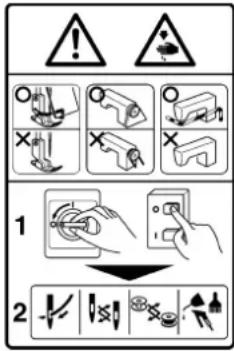
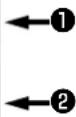
Hazardous voltage will cause injury.
Turn off main switch and unplug power cord and wait at least 5 minutes before opening this cover.

GEFAHR
natural_image
Line drawing of a sewing machine with hands operating it (no text or symbols)natural_image
Line drawing of a sewing machine with hands operating it (no text or symbols)
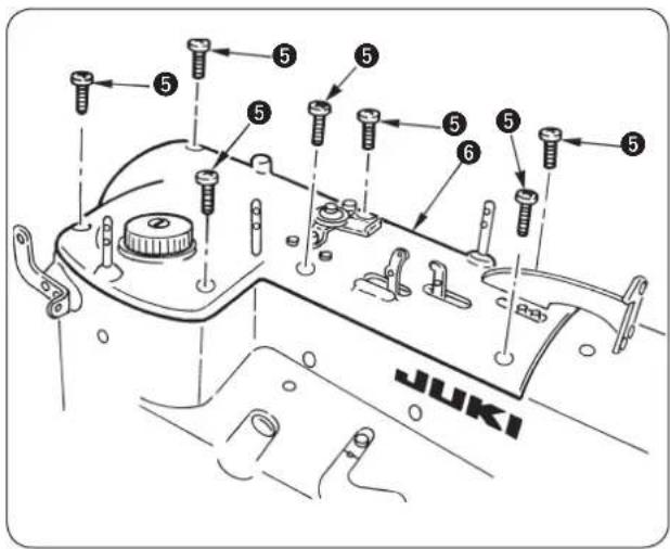
A
Standard
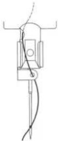
Sonderaus-
stattung
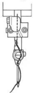
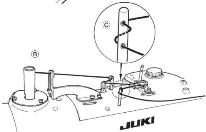
natural_image
Mechanical assembly diagram showing gear and valve connections (no text or labels)natural_image
Technical line drawing of a mechanical component with no visible text or symbolsnatural_image
Technical line drawing of a mechanical device with labeled components (no text or symbols present)Einstellverfahren
natural_image
Pure technical diagram of a mechanical component with no text or symbols
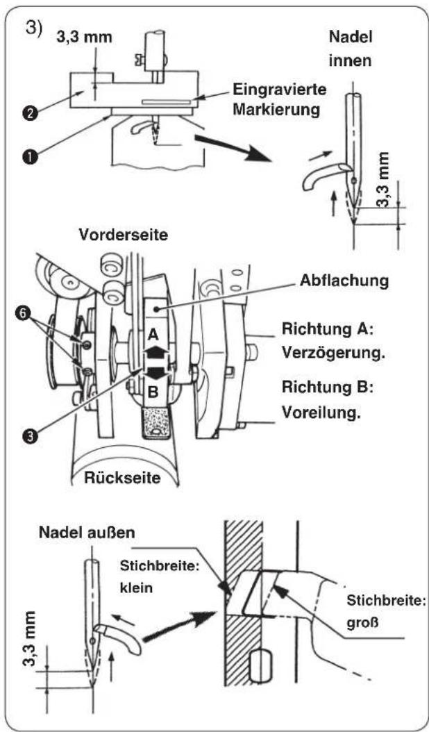
natural_image
Technical line drawing of a mechanical component with no visible text or symbols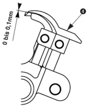
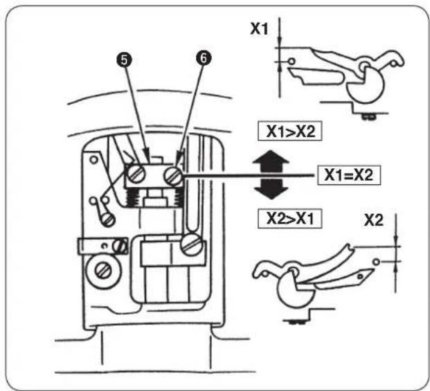
natural_image
Simple line drawing of a mechanical component with arrows indicating direction (no text or symbols)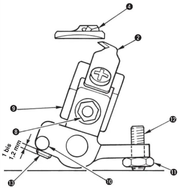
(Hinweis)
14050009
natural_image
Line drawing showing hands using a tool to adjust internal components of an engine (no text or symbols present)natural_image
Simple line drawing of a cylindrical object with a curved arrow indicating motion, no text or symbols present.
natural_image
Line drawing of a sewing machine with a hand adjusting the hook (no text or symbols)
natural_image
Technical line drawing of a mechanical component with labeled parts (no readable text or symbols)natural_image
Line drawing of a sewing machine with hands operating it (no text or symbols present)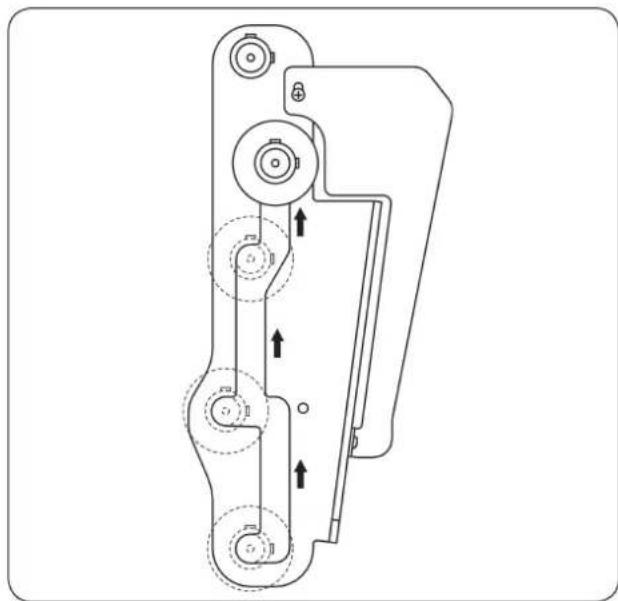
natural_image
Technical line drawing of a mechanical device with multiple circular components and directional arrows indicating motion (no text or symbols)natural_image
Diagram of a cable connector with connectors and wiring, no text or symbols presentnatural_image
Technical diagram of a mechanical or electrical component with labeled parts (no readable text or symbols)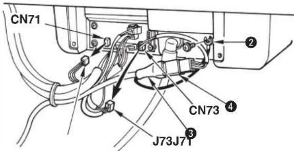

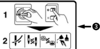
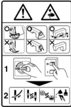


Hazardous voltage will cause injury.
Turn off main switch and unplug power cord and wait at least 5 minutes before opening this cover.

DANGER
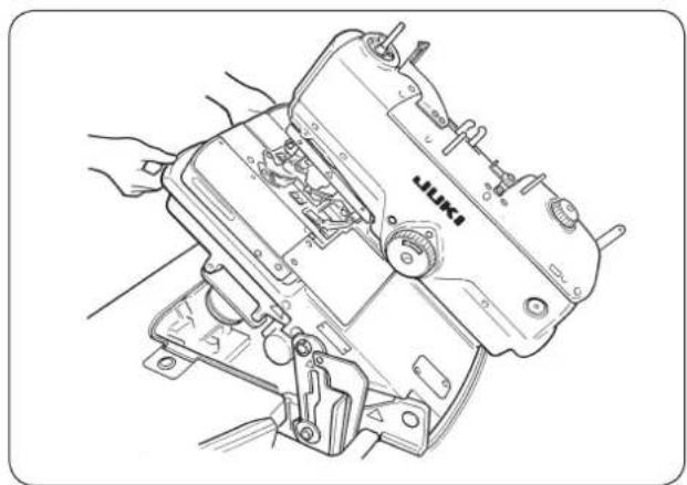
natural_image
Line drawing of a sewing machine with hands operating it (no text or symbols visible)natural_image
Line drawing of a sewing machine with hands operating it (no text or symbols)

natural_image
Technical line drawing of a mechanical device with no visible text or symbolsAvant
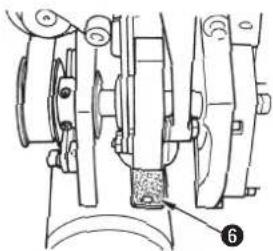
natural_image
Mechanical assembly diagram showing components like gears and a base with a labeled part (6), no readable text or symbols present.Arrière
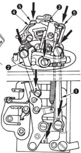
natural_image
Technical diagram showing mechanical assembly with labeled parts and a magnified inset of a component detail (no text or symbols present)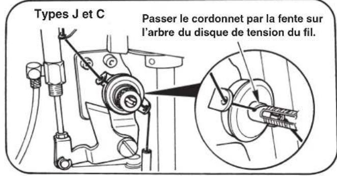
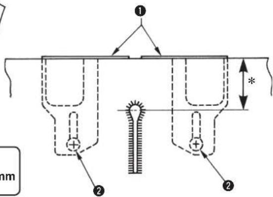

natural_image
Technical line drawing of a mechanical device with labeled components (no text or symbols present)natural_image
Pure technical diagram of a mechanical component with no text or symbols
[ Setting of needle thread tension ] Table1
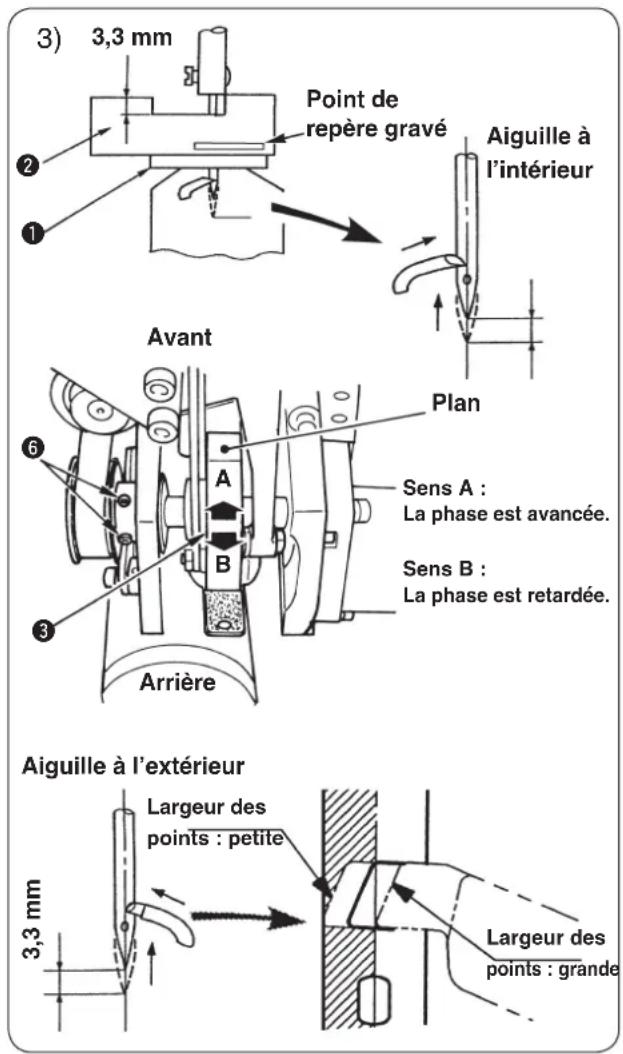
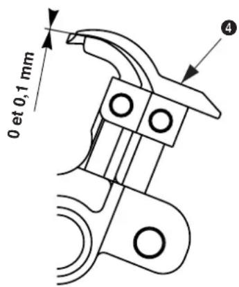
natural_image
Simple line drawing of a mechanical component with arrows indicating direction (no text or symbols)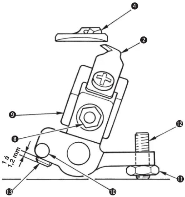


natural_image
Technical line drawing showing hands using a tool to adjust or install components of an engine component (no text or symbols present)natural_image
Simple line drawing of a cylindrical object with a curved arrow indicating rotation or movement, no text or symbols present.
natural_image
Line drawing of a sewing machine with a hand adjusting its hook (no text or symbols)natural_image
Technical line drawing of a mechanical assembly with hands and components (no visible text or symbols)
natural_image
Technical line drawing of a mechanical component with labeled parts (no readable text or symbols)natural_image
Line drawing of a sewing machine with hands operating it (no text or symbols)natural_image
Technical line drawing of a mechanical device with multiple circular components and directional arrows indicating motion (no text or symbols)natural_image
Technical diagram of a mechanical or electrical component with coiled wires and connectors (no text or symbols visible)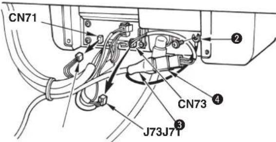

natural_image
Technical line drawing of a mechanical assembly with no visible text or symbolsSello del diagrama de enhebrado
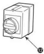
natural_image
Line drawing of a mechanical device with a circular component and an arrow pointing to a numbered label (12), no text or symbols present.① Interruptor de parada temporal
② Interruptor de prensatelas
③ Interruptor de arranque
4 Panel de operación
⑤ Caja de control
natural_image
Line drawing of a sewing machine with hands operating it (no text or symbols present)natural_image
Line drawing of a sewing machine with hands operating it (no text or symbols)

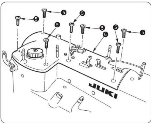
natural_image
Technical line drawing of a mechanical device with labeled components (no text or symbols present)Interruptor de prensatelas ①.

natural_image
Diagram of a mechanical spring-loaded component with a central pin and threaded base (no text or symbols)Número de puntadas

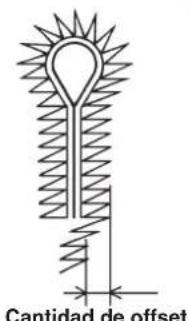
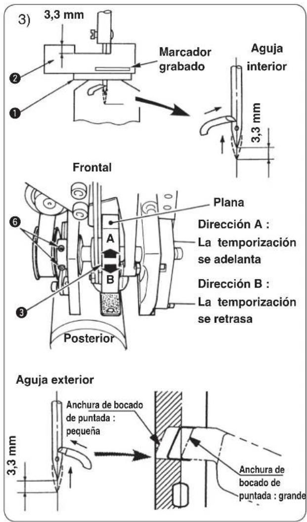
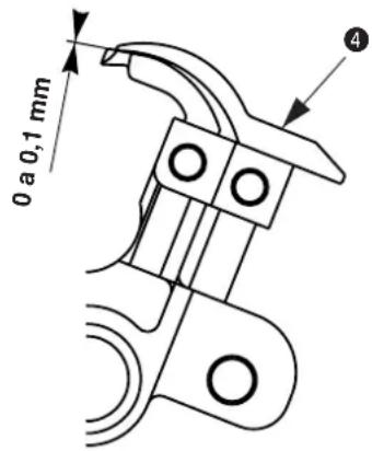
natural_image
Simple line drawing of a bed supported by two vertical supports, with no text or symbols present.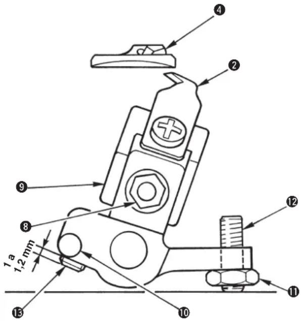
(Referencia)
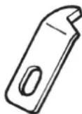
14050009
natural_image
Technical line drawing showing hands using a tool to adjust mechanical components (no text or symbols present)natural_image
Simple line drawing of a cylindrical object with a curved arrow indicating motion or force, no text or symbols present.
natural_image
Line drawing of a sewing machine with a hand adjusting its hook (no text or symbols)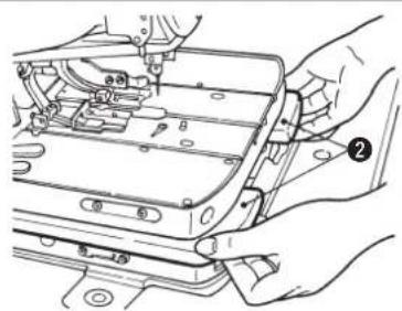
natural_image
Technical line drawing of a mechanical assembly with hands and components (no visible text or symbols)
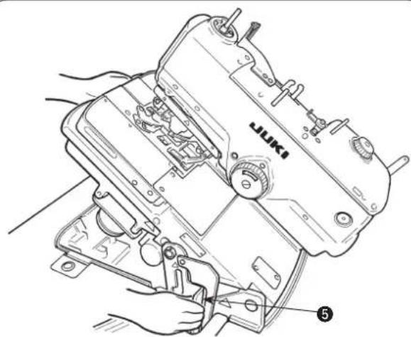
natural_image
Technical line drawing of a mechanical component with labeled parts (no readable text or symbols)natural_image
Line drawing of a sewing machine with hands operating it (no text or symbols)natural_image
Technical line drawing of a mechanical device with multiple circular components and directional arrows indicating motion (no text or symbols)natural_image
Diagram of cable connections with a device and connectors, no text or symbols present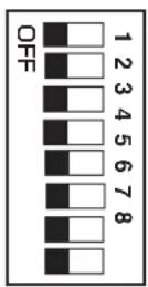
Corte de hilo largo
Presser holding plate
natural_image
Technical line drawing of a mechanical or electrical component with no visible text, numbers, or symbols.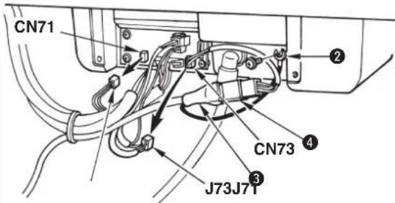


natural_image
Technical line drawing of a mechanical assembly with no visible text or symbols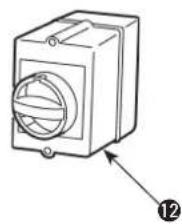
natural_image
Technical line drawing of a mechanical component with a circular housing and labeled part (12), no text or symbols present.natural_image
Line drawing of a sewing machine with hands operating it (no text or symbols)natural_image
Line drawing of a sewing machine with hands operating it (no text or symbols)
■ Come rimuovere
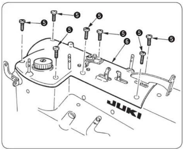
natural_image
Technical diagram of a mechanical assembly with labeled parts and a magnified inset showing internal components (no text or symbols present)natural_image
Technical line drawing of a mechanical assembly with no visible text or symbols
* Tipo S : da 13,5 a 30 mm
* Tipi J, C e T : da 10,0 a 26 mm
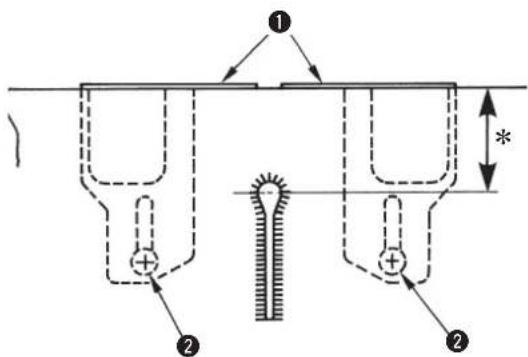
natural_image
Technical line drawing of a mechanical device with labeled components (no text or symbols present)
natural_image
Pure technical diagram of a mechanical component with no text or symbols
| No. (a) | Lunghezza punti(n) | Numero di | Quantità di sovrapposizione(b) | Larghezza dell'oscillazione dell'ago(c) |
| 52 | 3.0 | 4 | 1.5 | - 0.5 |
| 53 | 4.0 | 5 | 1.5 | - 0.5 |
| 54 | 5.0 | 6 | 1.5 | - 0.5 |
| 55 | 6.0 | 7 | 1.5 | - 0.5 |
| 56 | 7.0 | 8 | 1.5 | - 1.0 |
| 57 | 3.0 | 5 | 1.5 | - 0.5 |
| 58 | 4.0 | 6 | 1.5 | - 0.5 |
| 59 | 5.0 | 7 | 1.5 | - 0.5 |
| 60 | 6.0 | 9 | 1.5 | - 0.5 |
| 61 | 7.0 | 10 | 1.5 | - 1.0 |
| 62 | 3.0 | 6 | 1.5 | - 0.5 |
| 63 | 4.0 | 8 | 1.5 | - 0.5 |
| 64 | 5.0 | 9 | 1.5 | - 0.5 |
| 65 | 6.0 | 11 | 1.5 | - 0.5 |
| 66 | 7.0 | 13 | 1.5 | - 1.0 |
| 67 | 3,0 | 4 | 1,0 | -1,0 |
| 68 | 4,0 | 5 | 1,0 | -1,0 |
| 69 | 5,0 | 6 | 1,0 | -1,0 |
| 70 | 6,0 | 7 | 1,0 | -1,0 |
| 71 | 3,0 | 5 | 1,0 | -1,0 |
| 72 | 4,0 | 6 | 1,0 | -1,0 |
| 73 | 5,0 | 7 | 1,0 | -1,0 |
| 74 | 6,0 | 9 | 1,0 | -0,5 |
| 75 | 3,0 | 6 | 1,0 | -1,0 |
| 76 | 4,0 | 8 | 1,0 | -1,0 |
| 77 | 5,0 | 9 | 1,0 | -1,0 |
| 78 | 6,0 11 | 1,0 | -1,0 |
| No. (a) | Lunghezza punti(n) | Numero di | Quantità di sovrapposizione(b) | Larghezza dell'oscillazione dell'ago(c) |
| 79 | 3,0 | 4 | 1,5 | -1,0 |
| 80 | 4,0 | 5 | 1,5 | -1,0 |
| 81 | 5,0 | 6 | 1,5 | -1,0 |
| 82 | 6,0 | 7 | 1,5 | -1,0 |
| 83 | 3,0 | 5 | 1,5 | -1,0 |
| 84 | 4,0 | 6 | 1,5 | -1,0 |
| 85 | 5,0 | 7 | 1,5 | -1,0 |
| 86 | 6,0 | 9 | 1,5 | -1,0 |
| 87 | 3,0 | 6 | 1,5 | -1,0 |
| 88 | 4,0 | 8 | 1,5 | -1,0 |
| 89 | 5,0 | 9 | 1,5 | -1,0 |
| 90 | 6,0 11 | 1,5 | -1,0 |
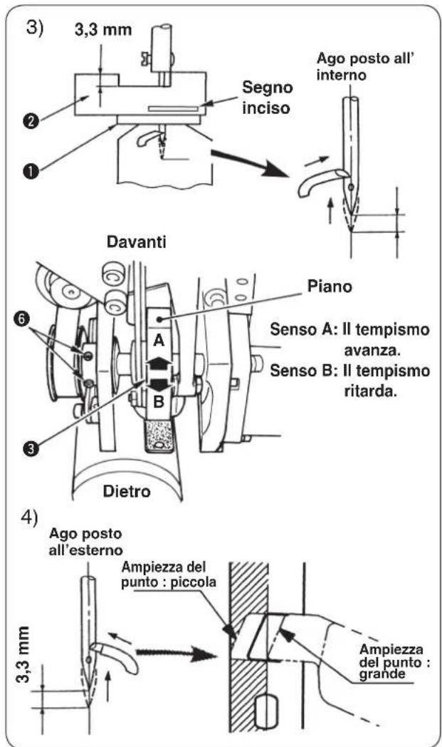
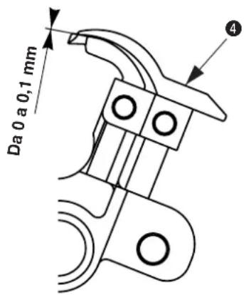
Da 1,2 a 1,5 mm
3,2 mm circa
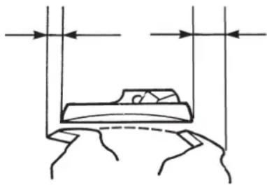
natural_image
Simple line drawing of a bed with vertical supports and horizontal arrows indicating measurement or alignment (no text or symbols)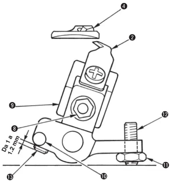
(Riferimento)
14050009
(Tipo lama destra)


natural_image
Line drawing showing two hands using a tool to adjust or install mechanical components (no text or symbols present)natural_image
Simple line drawing of a mechanical component with labeled parts (no text or symbols)
natural_image
Line drawing of a sewing machine being adjusted with a spring scale, no text or symbols presentnatural_image
Technical line drawing of a mechanical assembly with hands and components (no visible text or symbols)
natural_image
Technical line drawing of a mechanical component with labeled parts (no readable text or symbols)natural_image
Line drawing of a sewing machine with no visible text or symbolsnatural_image
Technical line drawing of a mechanical device with multiple circular components and directional arrows indicating motion (no text or symbols)

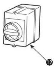
natural_image
Line drawing of a rectangular electronic device with a circular top and labeled component (no text or symbols)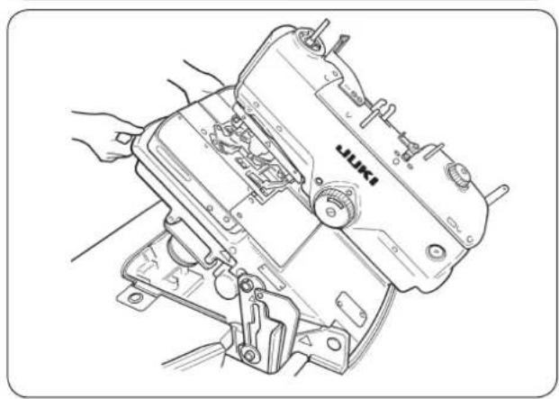
natural_image
Line drawing of a sewing machine with hands operating it (no text or symbols present)natural_image
Line drawing of a sewing machine with hands operating it (no text or symbols)■ 拆卸
■ 往机臂油槽加油
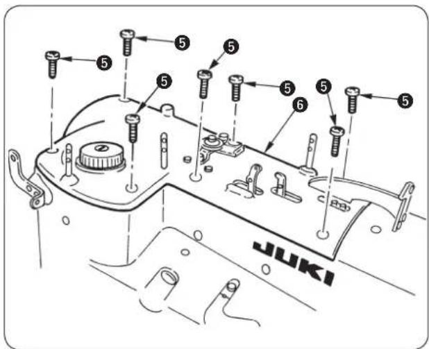
A
标准
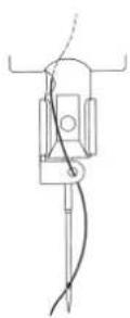
选购品
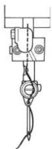
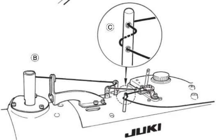
底线(弯针线)关系
危险
压脚开关(右)①
实行压脚上升 / 下降。
开始开关(左)②
实行缝制开始。

开关有效的时候,开始开关电灯闪亮。

标准装备。
(4) 脚踏开关
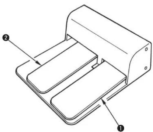
natural_image
Technical line drawing of a mechanical device with labeled components (no text or symbols present)压脚开关 ①
实行压脚上升 / 下降。
开始开关 ②
实行缝制开始。

为选购品。
6. 操作盘的使用方法

出货状态设定为加算计数。
| No. | a | ×b |
| 1 | 2.1 | ×3.2 |
| 2 | 2.5 | ×3.8 |
| 3 | 2.9 | ×4.4 |
| 4 | 3.0 | ×4.6 |
| 5 | 3.2 | ×5.4 |
| 6 | 2.7 | ×5.1 |
(2) 切割长度的设定
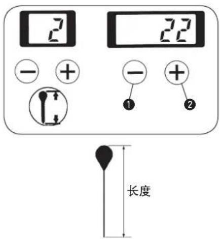
■ 上侧布切刀 · 切刀座的更换
■ 下侧布切刀 · 切刀座的更换
■ 压脚压力的调整
■ 调整方法
■ 调整时的布开放量的确认
■ 缝制的针线拉出量的调整
natural_image
Pure technical diagram of a mechanical component with no text or symbols2)修正缝制结束针数


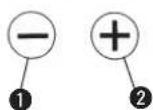

刀位置和缝制位置的偏差进行修正。
| SS/RS JS/CS TS | |
| 2.3 2.5 2.3 |
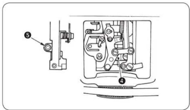
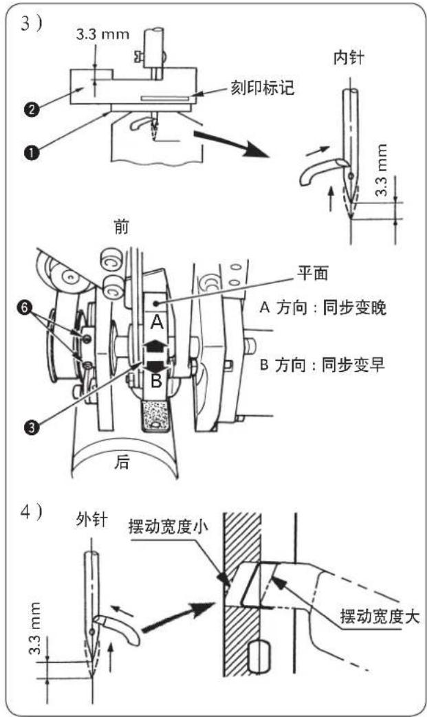
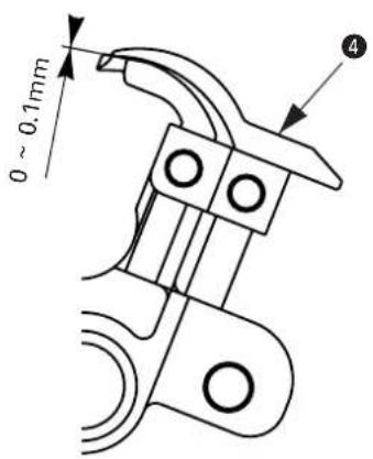
- 左分线器 ① 的高度位置
- 左分布器安装位置
- 上切刀规格
natural_image
Simple line drawing of a bed inside a trough with vertical arrows indicating direction (no text or symbols)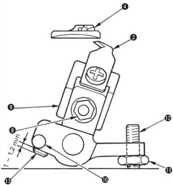
(参考)
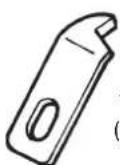
14050009
(右刀刃式)
S,R 规格(切长线)
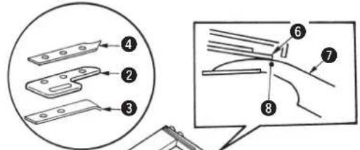
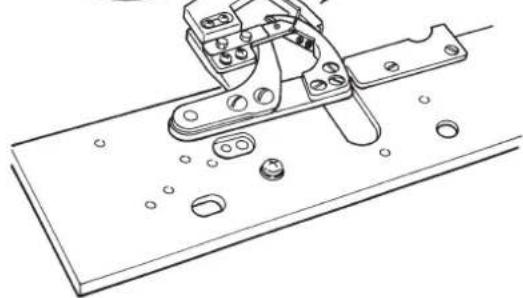
natural_image
Technical line drawing of a mechanical clamp or bracket assembly (no text or symbols)S,R 规格(切长线)

J,C 规格(切短线)

natural_image
Technical line drawing showing hands using a tool to adjust or install components of an automotive engine (no text or symbols present)natural_image
Simple line drawing of a cylindrical object with a curved arrow indicating motion or force, no text or symbols present.
期打扫控制箱风扇的滤清器
2。
natural_image
Line drawing of a sewing machine with a hand adjusting its hook (no text or symbols present)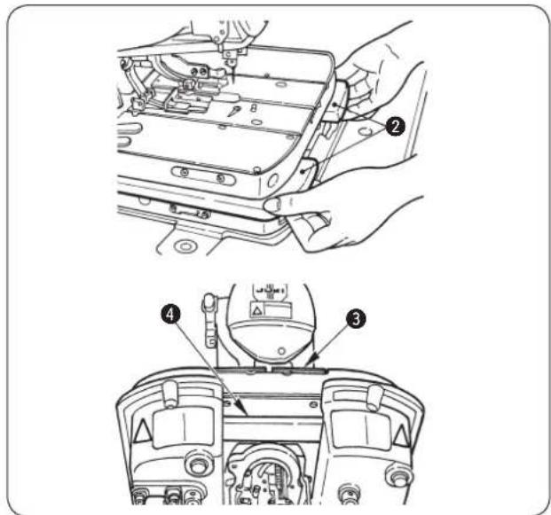
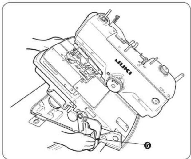
natural_image
Line drawing of a sewing machine with hands operating it, no text or symbols present1)请拧松止动气螺丝 ①,然后卸下来。
natural_image
Technical line drawing of a mechanical component with labeled parts (no readable text or symbols)natural_image
Line drawing of a sewing machine with hands operating it (no text or symbols present)natural_image
Technical line drawing of a mechanical device with multiple circular components and directional arrows indicating motion (no text or symbols)natural_image
Diagram of cable connections and a connector assembly with an arrow indicating direction (no text or symbols present)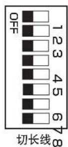
natural_image
Technical diagram of a mechanical or electrical component with labeled parts (no readable text or symbols)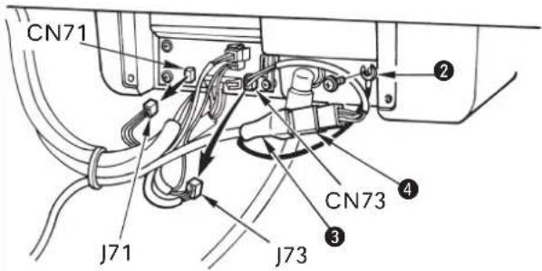
SEWING MACHINERY BUSINESS UNIT
2-11-1, TSURUMAKI, TAMA-SHI,
Copyright © 2000-2015 JUKI CORPORATION
• All rights reserved throughout the world.
- Alle Rechte weltweit vorbehalten.
- Tous droits réservés partout dans le monde.
- Reservados todos derechos en el mundo entero.
- Tutti i diritti sono riservati in tutto il mondo.
· 版权所有,严禁擅自转载、翻印本书的内容。
Please do not hesitate to contact our distributors or agents in your area for further information when necessary.
* The description covered in this instruction manual is subject to change for improvement of the commodity without notice.