Solamagic SMS1PLUS1400SW - Heating Etherma - Free user manual and instructions
Find the device manual for free Solamagic SMS1PLUS1400SW Etherma in PDF.

| Product type | Outdoor infrared heater |
| Model | Solamagic SMS1PLUS1400SW |
| Brand | Etherma |
| Power | 1400 W |
| Protection type | IP44 (minimum IP24 with connectors) |
| Protection class | I (grounded) |
| Electrical connection | 230 V, 50/60 Hz |
| Dimensions (approx.) | Length: 625 mm, width: 280 mm |
| Weight | Approximately 3-4 kg depending on mounting |
| Average lifespan | 5000 hours (heating tube) |
| Mounting type | Horizontal or vertical wall, horizontal or angled ceiling |
| Minimum mounting height | 1.80 m above ground |
| Main functions | Infrared heating, adjustable orientation, built-in switch (depending on version) |
| Material | Metal housing, aluminum reflector |
| Light source | Infrared halogen lamp |
| Maintenance and cleaning | Wipe with a soft damp cloth, do not use chemical products |
| Safety | Do not cover, observe safety distances, use a 16A type C fuse |
| Spare parts | Halogen tube, power cable, switch, mounting kit |
| Warranty | 5 years (unit), 12 months/5000 h (heating tube) |
| General information | Made in Germany, outdoor use |
Frequently Asked Questions - Solamagic SMS1PLUS1400SW Etherma
User questions about Solamagic SMS1PLUS1400SW Etherma
0 question about this device. Answer the ones you know or ask your own.
Ask a new question about this device
Download the instructions for your Heating in PDF format for free! Find your manual Solamagic SMS1PLUS1400SW - Etherma and take your electronic device back in hand. On this page are published all the documents necessary for the use of your device. Solamagic SMS1PLUS1400SW by Etherma.
USER MANUAL Solamagic SMS1PLUS1400SW Etherma
natural_image
3D rendering of a cylindrical air conditioner unit with grid pattern and ventilation slots (no text or symbols)SOLAMAGIC
natural_image
Technical line drawing of a mechanical device with three circular insets showing close-ups of components (no text or symbols)natural_image
Line drawing of a U-shaped metal bracket with mounting holes (no text or symbols)natural_image
Isometric line drawing of a metal bracket with mounting holes (no text or symbols)natural_image
Isometric line drawing of a bracket with mounting holes (no text or symbols)natural_image
Technical line drawing of a cylindrical mechanical component with mounting brackets (no text or symbols)natural_image
Technical line drawing of a structural component with internal grid and mounting brackets (no text or symbols)Einzelheit A
natural_image
Technical line drawing of a mechanical assembly with no visible text or symbolsInbetriebnahme
natural_image
3D rendering of a cylindrical air conditioner unit with grid pattern and ventilation slots (no text or symbols visible)SOLAMAGIC
natural_image
Technical line drawing of a mechanical assembly with three circular insets showing close-ups of components (no text or symbols)natural_image
Line drawing of a U-shaped metal beam with four side supports (no text or symbols)1. Montage warmtestraler met beugel
natural_image
Isometric line drawing of a mechanical bracket or bracket (no text or symbols)natural_image
Isometric line drawing of a bracket with mounting holes (no text or symbols)natural_image
Technical line drawing of a modular air vent or cooling unit with internal structure and mounting brackets (no text or symbols)Detail A
Stap 3: Buitenkader monteren
natural_image
Technical line drawing of a mechanical assembly with no visible text or symbolsInbedrijfstelling
natural_image
3D rendering of a cylindrical air conditioner unit with grid pattern and ventilation slots (no text or symbols)SOLAMAGIC
Monterings- og brugsanvisning
S1 Infrarød radiator 1400 W, IP44 (IR05001; IR05026)
S1 Infrarød radiator 2000 W, IP44 (IR05002; IR05027)
S3 Infrarød radiator 2500 W, IP44 (IR05008; IR05028)
D3 Infrarød radiator 2000 W, IP44 (DS 05002; DS 05028)
D3 Infrarød radiator 2000 W, IP45 (DS 05006)
Indholdsfortegnelse
natural_image
Line drawing of a U-shaped metal beam with four end points (no text or symbols)natural_image
Isometric line drawing of a metal bracket with mounting holes (no text or symbols)natural_image
Isometric line drawing of a bracket with mounting holes (no text or symbols)| Apparattype Effekt | Vægmontering Loftsmontering | |||
| horisontal vertikal horisontal skrå | ||||
| IR 05008 2500 W | √ | √ | ||
| DS 05002 2000 W | √ | √ | ||
| DS 05006 2000 W | √ | √ | ||
Bemærk:
Sørg for en fast, permanent sikker sammenskruning.
natural_image
Technical line drawing of a structural component with internal grid and mounting brackets (no text or symbols)Detalje A
natural_image
Technical line drawing of a mechanical assembly with no visible text or symbolsIbrugtagning
natural_image
3D rendering of a cylindrical air conditioner unit with grid pattern and ventilation slots (no text or symbols)SOLAMAGIC
natural_image
Line drawing of a U-shaped metal bracket with mounting holes (no text or symbols)natural_image
Isometric line drawing of a metal bracket with mounting holes (no text or symbols)Kun tillatt for veggmontering!
natural_image
Isometric line drawing of a bracket with mounting holes (no text or symbols)| Apparattype Ytelse | Veggmontering Takmontering | |||
| horisontalt vertikalt horisontalt skrätt | ||||
| IR 05008 2500 W | √ | √ | ||
| DS 05002 2000 W | √ | √ | ||
| DS 05006 2000 W | √ | √ | ||
Merk:
natural_image
Technical line drawing of a cylindrical mechanical component with mounting brackets (no text or symbols)3. Montering av stråleovn med takinnebyggingsramme (Apparattype IR05026, IR05027, IR05028, DS05028)
Trinn 2: Forbered monteringsstedet
natural_image
Technical line drawing of a structural component with internal grid and mounting brackets, labeled 'Detalj A' (no text or symbols on the diagram itself)Trinn 3: Monter dekkrammen
Obs: Fare for personskader! Bruk alltid arbeidshansker!
natural_image
Technical line drawing of a mechanical assembly with no visible text or symbolsIgangsetting
natural_image
3D rendering of a cylindrical air conditioner unit with grid pattern and ventilation slots (no text or symbols visible)natural_image
Technical line drawing of a mechanical device with three circular insets showing close-ups of components (no text or symbols)natural_image
Line drawing of a U-shaped metal bracket with mounting holes (no text or symbols)1. Montering avvärmeaggregat med bygel
| Aggregattyp Effekt | Väggmontering Takmontering | |||
| horisontell vertikal horisontell vertikal | ||||
| IR05001 1400 W | √ | √ | √ | |
| IR05002 2000 W | √ | √ | √ | |
natural_image
Isometric line drawing of a metal bracket with mounting holes (no text or symbols)| Aggregattyp E ekt | Väggmontering Takmontering | |||
| horisontell vertikal horisontell sned | ||||
| IR05001 1400 W | √ | √ | ||
| IR05002 2000 W | √ | √ | ||
natural_image
Isometric line drawing of a bracket with mounting holes (no text or symbols)| Aggregattyp Effekt | Väggmontering Takmontering | |||
| horisontell vertikal horisontell sned | ||||
| IR 05008 2500 W | √ | √ | ||
| DS 05002 2000 W | √ | √ | ||
| DS 05006 2000 W | √ | √ | ||
Information:
natural_image
Technical line drawing of a cylindrical mechanical component with mounting brackets (no text or symbols)natural_image
Technical line drawing of a mechanical assembly with no visible text or symbolsIdrifttagande
natural_image
3D rendering of a cylindrical air conditioner unit with grid pattern and ventilation slots (no text or symbols visible)SOLAMAGIC
natural_image
Technical line drawing of a mechanical device with three circular insets showing close-ups of components (no text or symbols)natural_image
Line drawing of a U-shaped metal bracket with mounting holes (no text or symbols)natural_image
Isometric line drawing of a metal bracket with mounting holes (no text or symbols)natural_image
Isometric line drawing of a bracket with mounting holes (no text or symbols)natural_image
Technical line drawing of a cylindrical mechanical component with mounting brackets (no text or symbols)natural_image
Technical line drawing of a structural component with internal grid and mounting brackets (no text or symbols)Yksityiskohta A
natural_image
Technical line drawing of a mechanical assembly with no visible text or symbolsKäyttöönotto
natural_image
3D rendering of a cylindrical air conditioner unit with grid pattern and ventilation slots (no text or symbols visible)SOLAMAGIC
Installation and Instruction Manual
S1 Infrared Radiator 1400 W, IP44 (IR05001; IR05026)
S1 Infrared Radiator 2000 W, IP44 (IR05002; IR05027)
S3 Infrared Radiator 2500 W, IP44 (IR05008; IR05028)
D3 Infrared Radiator 2000 W, IP44 (DS 05002; DS 05028)
D3 Infrared Radiator 2000 W, IP45 (DS 05006)
Contents
Safety and operating instructions....123
Scope of supply....124
Installation instructions....125
Initial operation....137
Cleaning instructions....137
Guarantee conditions ....138
Additional instructions....139
Appendices
- Appendix 1:
AX
Technicaldata
- Appendix 2:
AX
Safety distances
- Appendix 3:
AX
Radiation diagram
Safety and operating instructions
Please observe the following instructions:
- Carefully read through the instruction manual prior to installation and store the manual safely.
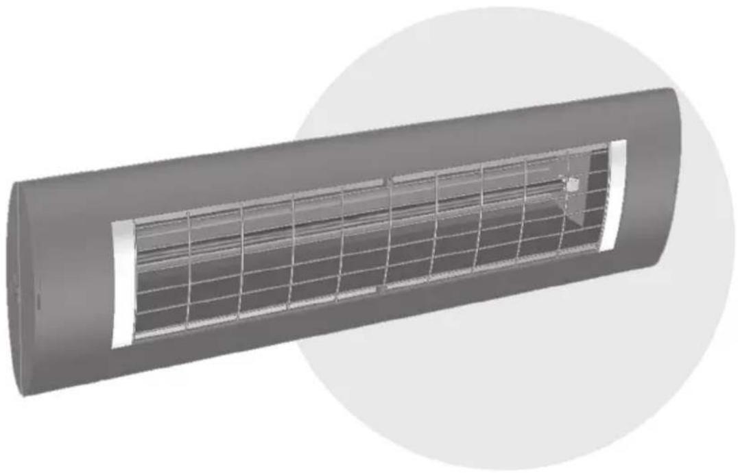
- This heater is intended for outdoor installation, either attached to a building wall or some other solid construction. It is not intended to be used indoors to provide heating up to a pleasant temperature level.
- The heater must only be used by adults. Children must not play with the heater. Children younger than 3 years old must be kept away from the heater unless they are continuously monitored. Children younger than eight years old must not switch the heater on and off, insert the plug in the socket, clean the heater nor perform any maintenance work.
Caution - Some parts of this product can become very hot and cause burns. Special care is required when children and vulnerable persons are present.
- Installation tasks must be properly carried out by a qualified person in accordance with VDE 0100 installation instructions (if applicable, also including Parts 559 and 701).
- When carrying out any work, always switch the system to a zero-volt state (disconnect mains plug; circuit-breaker off). Switch on the heater only after all the cables have been completely connected.
- The heater must be connected to a switched domestic electrical supply protected by a fuse of rating at least 16A slow (type C16A).
- Do not install directly under sockets, junction boxes, switches or electrical cabling.
- Electrical sockets may only be located in the positions specified in Appendix 2.
- Do not mount the radiant heater close to curtains or combustible materials in accordance with VDE 0100, Part 559.
- The heater is as a minimum compliant to an IP24 degree of protection, provided all connectors (heater plug, plugs for expansion components) are plugged in, and is approved for outdoor use.
- Never leave the heater unattended.
- Do not cover the heater when it is switched on or still hot; there is a risk of fire.
- To adjust the radiation direction, switch the heater off and allow to cool.
- Do not look directly at an operating IR halogen lamp for a long period and from a short distance.
- IR halogen lamps are sensitive to direct skin contact (do not touch with bare
fingers). Grease or other contamination can be removed with an alcohol-soaked cloth.
- To maintain the service life of the IR halogen lamp, it must be protected against vibrations, impacts and contaminants such as acids, ammonia, cement dust, etc.
- The IR halogen lamp must be protected against mechanical loading. It must be replaced, if changes (dark spots, deformation) become apparent or the rated lifetime is reached.
- Damaged equipment elements such as lead, rocker switch, sealing collar or heating tube must always be replaced. The unit must be immediately dismantled and stored dry.
- Repair work (replacement of a defective power lead, a defective heating tube or similar) must only be carried out by the customer service of the manufacturer or an authorised dealer.
- Cleaning and maintenance work must only be carried out by adults with sufficient expertise.
Scope of supply
IR radiant heater
Mains connection lead (supplied with heaters that do not come with a fixed lead)
Mounting bracket including fastenings (supplied)
Manual
Installation instructions
- The radiator must only be installed using suitable fastenings (e.g. use M 6 x 60 bolts with steel anchors in a stone or concrete substrate) on firm, load-bearing, normally combustible, flame-resistant or non-combustible substrate.
- If radiator and socket are not installed on the same surface, it must be ensured that the field of radiation cannot be directed towards the socket. Failing this, it must be ensured that the socket cannot heat up to more than 70^ C during heater operation.
- The safety distances given in Appendix 2 must be observed.
- The area in which the heat acts can be estimated from the radiation diagram (Appendix 3). The diagram shows the sizes of the irradiated areas at various distances from the radiant heater and in each case the maximum radiation intensity.
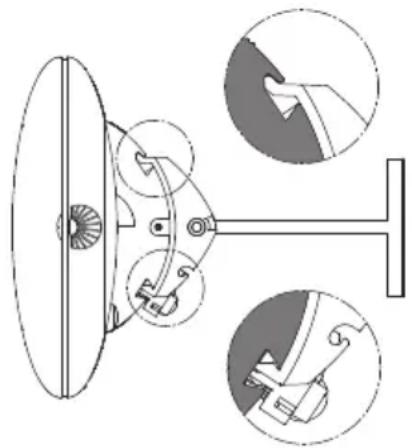
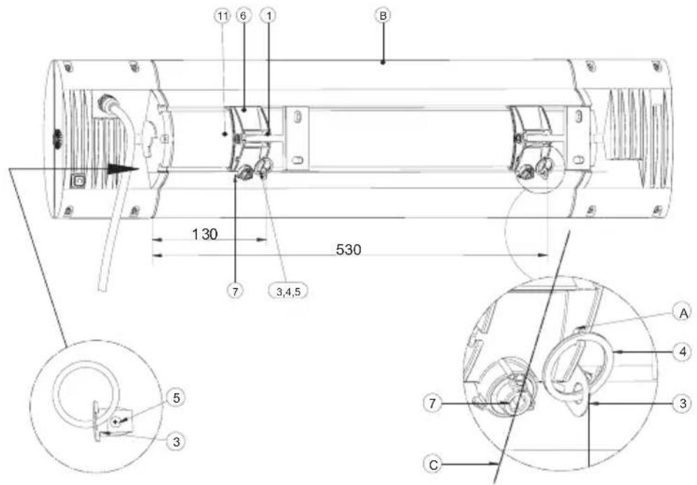
• Installation height: at least 1.80 m above the ground - The radiator must be installed with the hammer groove upwards. The hammer groove can be seen when looking at the housing side with the power lead (see figure below).
natural_image
Technical line drawing of a mechanical device with three circular insets showing close-ups of components (no text or symbols)During mounting always up
During mounting
always down
- The S3 und D3 (IR 05008, IR 05028, DS 05002, DS 05006, DS 05028) radiators must be fitted and operated in a horizontal position.
- Only for types IR 05001 and IR 05002: If mounted on a sloping ceiling or vertical wall, the heater must be fitted with the power lead assembly facing „down“.
natural_image
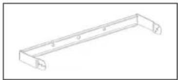
Line drawing of a U-shaped metal bracket with mounting holes (no text or symbols)1. Installation, radiant heater with bracket
| Heater type Power | Wall installation Ceiling installation | |||
| Horizontal Vertical Horizontal Inclined | ||||
| IR 05001 1400 W | √ | √ | √ | |
| IR 05002 2000 W | √ | √ | √ | |
- Secure the bracket while observing the safety distances and safety and operating instructions (see Appendix 2)
- Fit the bracket with 2 screws at a separation of 200 mm on the fastening surface.
- Where expansion components are used, the outer fastening points of the bracket must be used when installing on the wall (separation 350 mm)
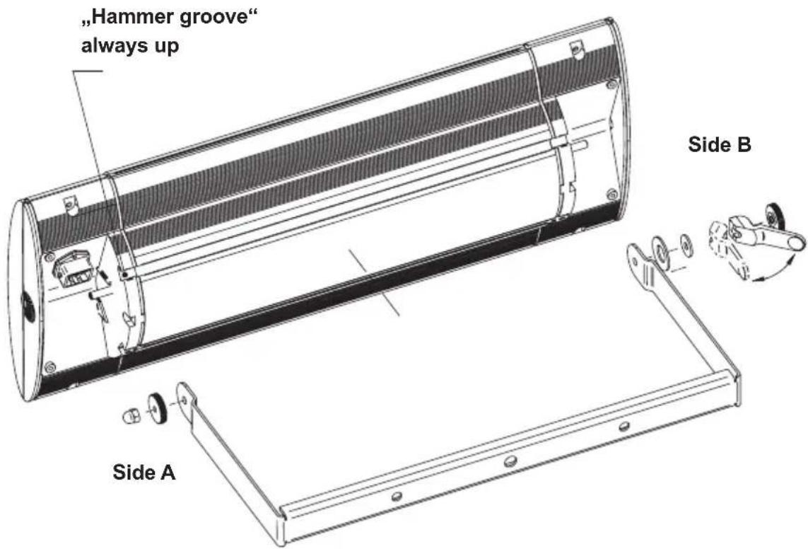
- Attach the heater starting on side B and when doing so slightly bend the bracket (Note! „Hammer groove“ always up)
- Side A: Fit knurled M6 nut and M6/10 mm cap nut.
- Tighten knurled nut by hand and tighten the cap nut with an open-ended 10 mm (AF) spanner.
- Side B: Fit spring washer, flat washer, cam lever and M6 knurled nut. Hand-tighten the M6 knurled nut up to the pressure point on the cam lever. Clamp the cam lever in the bracket direction.
natural_image
Isometric line drawing of a metal bracket with mounting holes (no text or symbols)2a. Installation, radiant heater S1 with T-bracket
| Heater type Power | Wall installation Ceiling installation | |||
| Horizontal Vertical Horizontal | Inclined | |||
| IR05001 1400 W | √ | √ | ||
| IR05002 2000 W | √ | √ | ||
Only approved for wall mounting!
Step 1: Installing the T-brackts
- Secure the T-bracket (1) with the silicone plate (2) below it on the fastening surface with 2 screws each according to the following figure.
Step 2: Installing adapter claws on the T-bracket
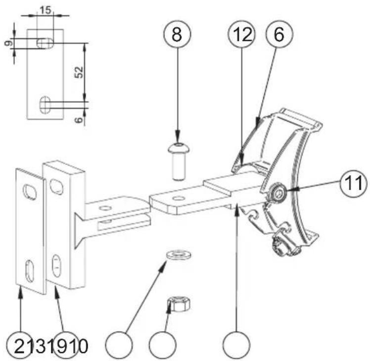
- Push the adapter claw (6) into the T-bracket (1) mounted on the fastening surface. Insert the M8x20/5 mm AF screw (8) into the hole. Insert washer (9) and tighten M8/13 mm AF nut (10).
- If the adapter claw (6) cannot be aligned facing downwards, screws (8) to (10) must be undone and the claw pulled out from the bracket. Then remove screws (11) and refit the middle part (13) with the cloth disc (12) rotated through 180^ on the adapter claw (6). Then refit the device at the wall bracket.
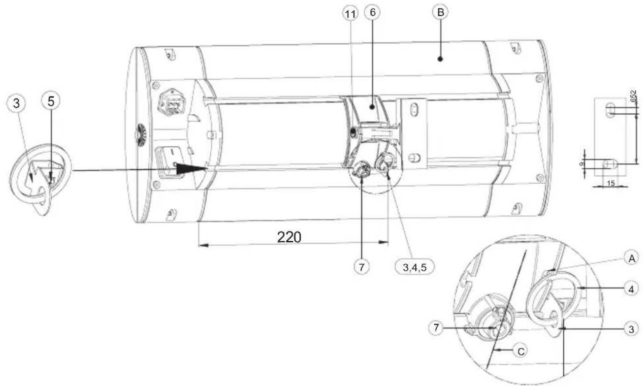
Step 3: Installing the heater on the wall mounting
- Push the securing lugs (3) with the ring (4) from the left side into the dovetail groove for approx. 220 mm
- Tighten the 3.5 × 6.5 screw (5).
- Align the eccentric tensioner (7) of the adapter claw (6) in the vertical direction (C), see figure below.
- Attach heater (B) at the top in the hammer groove side on the adapter claw (6) and swing in at the bottom on the eccentric tensioner side (7).
Warning: The adapter claw must now engage in each of the two device grooves (visual check)
- Tighten the eccentric tensioner (7) by turning the supplied 5 mm hex-key in a clockwise direction (approx. 80^ angle of turn). The heater must be tightly connected to the adapter claw so that it is free from play.
Attention: there is no rotation-stop; do not turn through 180^ – do not over-turn the eccentric spanner!
• Fit the retaining ring (4) in the cut-out (A) of the adapter claw (6).
- To set or adjust the direction of radiation, use a 5 mm Allen key to loosen the screws (11), shift the heater into the required direction and re-tighten the screws (11).
natural_image
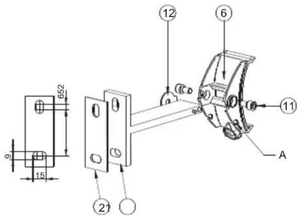
Isometric line drawing of a mechanical bracket or bracket (no text or symbols)2b. Installation, radiant heater S3 and D3 with T-brackets
| Heater type Power | Wall installation Ceiling installation | |||
| Horizontal Vertical Horizontal Inclined | ||||
| IR 05008 2500 W | √ | √ | ||
| DS 05002 2000 W | √ | √ | ||
| DS 05006 2000 W | √ | √ | ||
Note:
The radiant heater has a one-sided swivel range in the direction of the oblong hole side, depending on the mounting orientation of the T-bracket.
When mounting on a wall, the T-bracket must be mounted with the oblong hole side at the bottom (picture below), when mounting on the ceiling with the oblong hole side in front.
Step 1: Installing the T-brackts
• Install the S3 or D3 radiant heater using 2 T brackets at a separation of 400 mm while observing the safety distances and safety instructions (see Appendix 2).
- To make assembly easier, remove the adapter claw (6) from the T-bracket (1) by loosening the screws (11) (illustration below).
- Mount the T-bracket (1) with the silicone plate (2) underneath on the mounting surface with 2 screws each as shown in the following figure.
Step 2: Installing adapter claws on the T-brackets
- Fit adapter claws (6) at both of the T-brackets installed on the mounting surface, fit safety washer (12) between the T-bracket and adapter claw and screw in hex socket head screws (11) from outside into the T-bracket (Illustration above). In the case of ceiling mounting, the adapter claw must be rotated 180^ and screwed onto the holder, in contrast to the illustration.
Step 3: Installing the heater on the T-brackets
- Push the securing lugs (3) with the ring (4) from the cable side into the dovetail groove for approx. 530 mm and 130 mm.
- Tighten the 3.5 × 6.5 screws (5).
- Align the eccentric tensioner (7) of the adapter claw (6) in the vertical direction (C), see figure below.
- Attach heater (B) at the top in the hammer groove side on the adapter claws (6) and swing in at the bottom on the eccentric tensioner side (7).
Warning: The adapter claws must now engage in each of the two device grooves (visual check)
The securing lugs (3) must now be located directly alongside the adapter claws (6).
- Tighten the eccentric tensioners (7) by turning the supplied 5 mm hex-key in a clockwise direction (approx. 80^ angle of turn). The heater must be tightly connected to the adapter claws so that it is free from play.
Attention: there is no rotation-stop; do not turn through 180^ – do not over-turn the eccentric spanner!
- Fit each retaining ring (4) in the cut-out (A) of the adapter claw (6).
- To set or adjust the heat radiating direction, use a 5 mm hex-key to undo the screw (11, left adapter claw side according to the figure below), move the heater to the required radiating direction and re-tighten the screw (11).
natural_image
Technical line drawing of a cylindrical mechanical component with mounting brackets (no text or symbols)3. Installation, radiant heater with ceiling installation frame (device type IR05026, IR05027, IR05028, DS05028)
General instructions
- The ceiling installation frame is suitable for installation fastening in ceiling panels of min. thickness 10 mm and max. thickness 30 mm (Blind frame-Version max. 25 mm).
- In the case of heaters with light-coloured surface coatings (e.g. white), continuous operation may result in changes to the surface colour.
- The installation must not change or impair the existing ceiling stand.
- The minimum distances in accordance with Appendix 2 must be observed.
- The ceiling installation space must meet the following minimum dimensions for the necessary air circulation:
| Heater type Width in mm Length in mm | ||
| IR05026IR05027 | min. 500 min. 900 | |
| IR05028DS05028 | min. 600 min. 1200 |
The open spaces must not be constricted or covered by insulating material or otherwise.
- Two people are required for the installation.
- The electrical connection must be made outside the installation frame (inspection access).
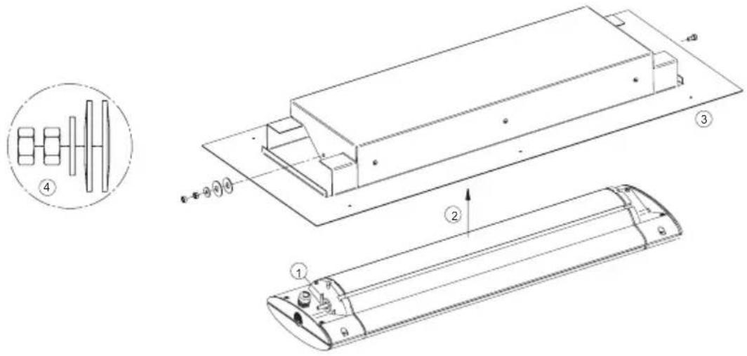
3a. Variant Direct Fitting:
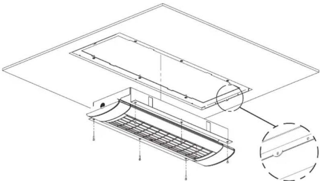
Step 1: Screwing the heater to the cover
- ① Push the large U-washer on to the bolt on the radiant heater.
- ② Insert the heater at an angle into the cover, until the bolt enters the hole in the cover.
- ③ Swivel the heater fully into the cover and using a tool tighten the bolt until it is fully home, applying a torque of 0.5 ~Nm .
- ④ Thread on two disc springs; the first with the arch towards the cover, the second with the arch facing outwards. Push the small U-washer onto the bolt, screw on the hexagon nut and lock with a second hexagon nut. It must be possible to easily swivel/tilt the heater into the cover with minimum friction.
Step 2: Preparing the installation space
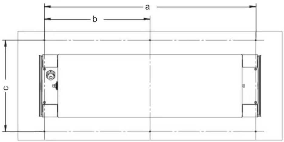
- Make a cut-out in the ceiling with dimension (x) mm and (y) mm:
| Heater type | Ceiling cutout in mm | Distance between fastening holes in mm | |||
| Width (x) L | length (y) a b | c | |||
| IR05026 IR05027 | 280 625 | 495 247,5 3 | 10 | ||
| IR05028 DS05028 | 280 850 | 720 360 310 | |||
- Drill fastening holes a and b in the ceiling panel.
Step 3: Mounting the heater in the installation space
- Connect the device to the electricity, but do not switch on.
- Position the device in the ceiling cut-out.
Warning:
The connecting cable must be led away directly from the device. It must be routed in the installation space away from the cut-out area.
- From the outside screw the installation frame to the ceiling panel using six 4 mm diameter screws.
Warning:
Ensure the screw joint is secure and permanent. If necessary, use additional mounting frames (accessories)!
3b. Blind frame variant:
Step 1: Preparing the installation space
- Make a cut-out in the ceiling with dimension (x) mm and (y) mm:
| Heater type | Ceiling cutout in mm | |
| Width (x) Length | (y) | |
| IR 05026; IR 05027 300 625 | ||
| IR 05028; DS 05028 300 850 | ||
- Place the mounting frame behind the ceiling so that the inner lugs are inserted into the cut-out.
- Centre the mounting frame over the cut-out and on the front side screw to the ceiling plate using the inner lugs.
- Center the mounting frame in the cutout and screw it to the front panel with the ceiling plate. For thin ceiling panels (< 15 mm), bend or remove the mounting tabs if necessary. (Detail A)
Step 2: Mounting the heater in the installation space
- Make the electrical connection to the device, but do not switch on.
- Screw the heater to the mounting frame using 6 M 4 x 18 screws and washers.
- Tighten the screws
natural_image
Technical line drawing of a structural component with internal grid and mounting brackets (no text or symbols)Detail A
Step 3: Installing the blind frame
Warning: Risk of injury! Always wear safety gloves!
- ① Apply pressure to the springs, until they engage in the retainer.
Warning: Risk of crushing due to springs jumping back. Do not reach into the clamping area of the springs!
• ② Fit an unlocking device at the kink in each spring and allow to hang out of the frame cut-out.
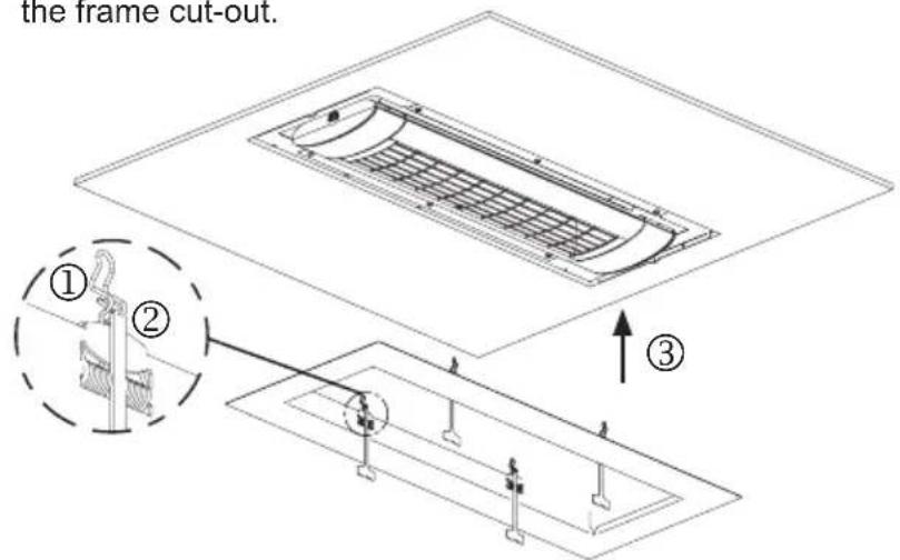
- ③ Positioning the frame: Position the pre-tensioned spring tips in the gap of the heater cover.
• ④ Press the blind frame against the cut-out in the ceiling - ⑤ Pull the unlocking devices down and allow each of the springs to snap against the mounting frame.
Note: Store the unlocking devices carefully somewhere for subsequent removal and re-installation.
Removal:
- Pull the blind frame at the outer edge from the ceiling until the clamping springs can be reached in the gap.
Warning: Risk of injury! Always wear safety gloves!
- Press the springs back and swivel the frame out of the installation space. Slowly release the springs.
OPTION
4. For expansion components for the radiant heater
- Expansion components can only be used for the intended device types.
- When using expansion components, the corresponding installation and instruction manual must be used without fail.
- If expansion components (e.g. wireless module) are used, the technical data in Appendix 1 changes.
natural_image
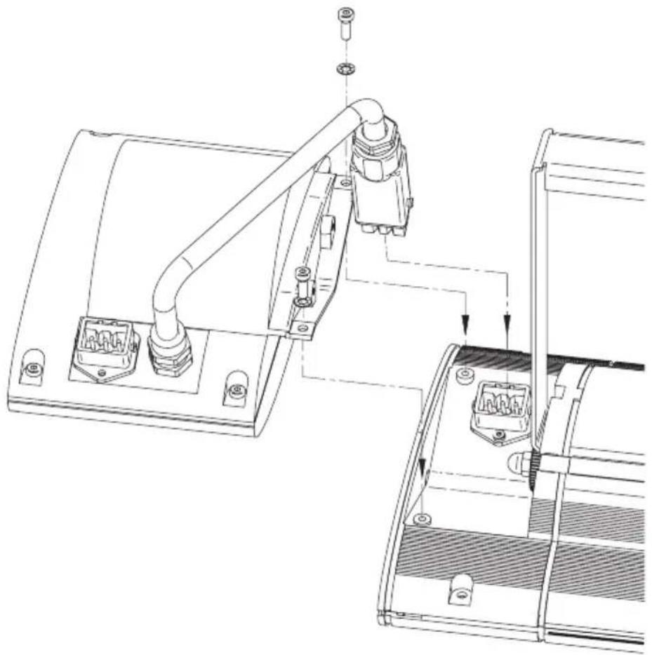
Technical line drawing of a mechanical assembly with no visible text or symbolsInitial operation
- Where fitted, completely remove the transport protection on the reflector.
- Connect the enclosed power lead (A) to the heater (B) and secure using the retaining clip (C).
- Make the connection to the power supply (Schuko/mains plug)
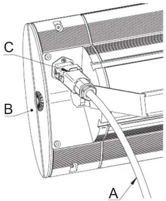
For those models without a switch, heating starts immediately upon plugging of the plug into the socket. For models with a switch or radio receiver, heating starts upon switching of the switch or via remote control.
Cleaning instructions
- Disconnect the device from the mains.
- Allow the casing to cool.
- Wipe the casing clean with a moist, soft cloth. Do not use any detergent.
Never immerse the device in liquids nor spray-wash it.
Possible discolouration of the protective grille due to heat effects results from normal physical processes and is not a defect.
Guarantee conditions for S1, S3 and D3 heaters
We guarantee this heater in accordance with the following conditions:
- We will repair, free of charge, in accordance with the following provisions, damage or defects to the heater, which can be proven to be due to a factory defect, if they are reported to us immediately upon discovery on the heater and within 5 years of delivery to the end user. The duration of the guarantee for the heating tube is 12 months up to a maximum 5000 operating hours within this period. The guarantee does not cover minor deviations from the design properties that are irrelevant for the value and usability of the heater or damage caused by abnormal environmental conditions or unsuitable operating conditions. Likewise the guarantee does not cover damage caused by exceptional climatic conditions, abnormal environmental conditions or unsuitable operating conditions. Your dealer will be happy to advise about heater versions for use in such cases.
No guarantee can be given if the damage or defects on the heater arise from faulty installation or failure to observe the operating instructions.
-
The guarantee is fulfilled in that defective heaters will be repaired, or replaced by flawless heaters, at our discretion, and free of charge. Heaters, for which a performance of guarantee is claimed with reference to this guarantee, must be handed over or sent to the manufacturer or an authorised service centre. The sender is liable for the transport risk associated with the sending. The shipping, transport, travel and labour costs of the end user are not refunded. Proof of purchase with the date of purchase and/or delivery date plus a detailed description of the fault must always be presented. Replaced heaters become our property.
-
Any guarantee claim becomes void if repairs or adjustments are made by persons who are not authorised by us or if our heaters are provided with spare parts, supplementary parts or accessories that are not original parts, and have caused a defect. The same applies if the name plate or the device number has been removed or rendered illegible.
-
Excluded from this guarantee are damages or defects from incorrect connection, improper handling, mechanical damage, particularly to the heating tube, and failure to observe the installation and operating instructions. We accept no liability for consequential damage.
-
Guarantee performances do not extend the guarantee period nor do they initiate a new guarantee period. The guarantee period for any fitted spare parts ends with the guarantee period for the device as a whole. If a defect or deficiency cannot be eliminated or the rectification of defects is declined by us or unreasonably delayed, an equivalent replacement will be delivered, free of
charge, upon request of the customer. In case of replacement, we reserve the right to enforce a reasonable usage charge for time of use up until the time of replacement.
These guarantee conditions apply from 01/01/2021 for heaters purchased in a country of the European Union, even if you use it in a foreign country. The guarantee conditions have no effects on the statutory guarantee claim.
Additional instructions
Subject to technical changes.
This product is „Made in Germany“.
For more products and accessories from SOLAMAGIC ^® , see:
www.SOLAMAGIC.com
Please note the following terminology in the appendix
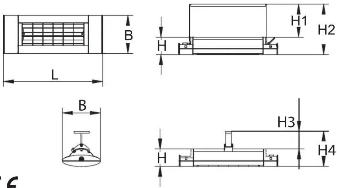
Appendix 1: Technical data
| 0 | Heater type | 6 | Dimensions length x width x height (mm) |
| 1 | Heater power (W) | 7 | Weight (kg) |
| 2 | Power connection | 7a | Additional weight for the version with blind frame (kg) |
| 3 | Protection type | 8 | Service life (t) |
| 4 | Degree of protection | 9 | Distance (mm) |
| 5 | Approvals |
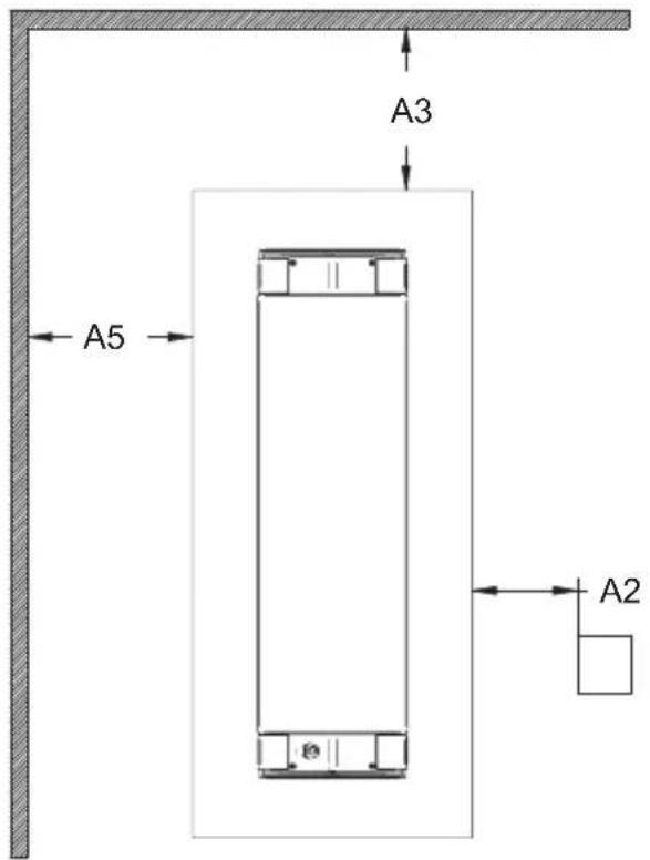
Appendix 2: Safety distances
| 0 | Heater type | 6 | Front view |
| 1 | Wall mounting, horizontal (Not suitable for device type IR 05026, IR 05027, IR 05028, DS 05028) | 7 | Plan view |
| 2 | Minimum distances in mm | 8 | Ceiling installation |
| 3 | Heater power (W) | 9 | (for device type IR 05001 and IR 05002 solely with U-bracket) |
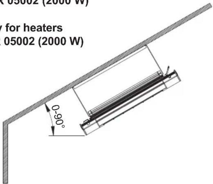
| 4 | Wall mounting, vertical (Only for heater type IR 05001 and IR 05002) | 10 | Inclined installation only for heaters IR 05001 (1400 W) and IR 05002 (2000 W) |
| 5 | When installing vertically, the connection lead must always be at the lower end! | 11 | Ceiling installation only for heater type IR 05026, IR 05027, IR 05028 and DS 05028 |
| A1 | Distance to heated surface A5 Distance to the near wall | ||
| A2 | Distance to the socket A6 Distance to the irradiated wall | ||
| A3 | Distance to the side wall A7 | Ceiling installation depth / false ceiling clearance | |
| A4 | Distance to overhead ceiling a Adjustment range | ||
| D | Distance floor / heater | ||
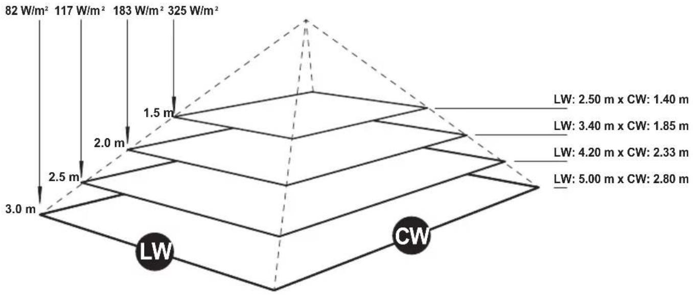
Appendix 3 Radiation diagram
| 1 | Maximum heat | 2 | Heated area |
natural_image
3D rendering of a cylindrical air conditioner unit with grid pattern and ventilation slots (no text or symbols)SOLAMAGIC
natural_image
Technical diagram of a mechanical device with three circular insets showing close-ups of components (no text or labels)natural_image
Simple line drawing of a metal bracket with four ends and a flat top (no text or symbols)natural_image
Isometric line drawing of a bracket with mounting holes (no text or symbols)natural_image
Isometric line drawing of a bracket with mounting holes (no text or symbols)natural_image
Technical line drawing of a cylindrical mechanical component with mounting brackets (no text or symbols)3a. Raccord direct variant
natural_image
Technical line drawing of a mechanical assembly with no visible text or symbolsMise en service
natural_image
3D rendering of a cylindrical air conditioner unit with grid pattern and ventilation slots (no text or symbols)SOLAMAGIC
natural_image
Technical line drawing of a mechanical device with three circular insets showing close-ups of components (no text or symbols)natural_image
Line drawing of a U-shaped metal beam with evenly spaced supports (no text or symbols)natural_image
Isometric line drawing of a metal bracket with mounting holes (no text or symbols)natural_image
Isometric line drawing of a bracket with mounting holes (no text or symbols)natural_image
Technical line drawing of a cylindrical mechanical component with mounting brackets (no text or symbols)natural_image
Technical line drawing of a structural component with internal grid and mounting brackets (no text or symbols)Einzelheit A
natural_image
Technical line drawing of a mechanical assembly with no visible text or symbolsMessa in servizio
natural_image
3D rendering of a cylindrical air conditioner unit with grid pattern and ventilation slots (no text or symbols)SOLAMAGIC
natural_image
Technical line drawing of a mechanical device with three circular insets showing close-ups of components (no text or symbols)natural_image
Technical line drawing of a metal L-bracket with mounting holes (no text or symbols)natural_image
Isometric line drawing of a metal bracket with mounting holes (no text or symbols)natural_image
Isometric line drawing of a bracket with mounting holes (no text or symbols)natural_image
Technical line drawing of a cylindrical mechanical component with mounting brackets (no text or symbols)natural_image
Technical line drawing of a structural component with internal structure and mounting holes (no text or symbols)Detalle A
natural_image
Technical line drawing of a mechanical assembly with no visible text or symbolsActivación
natural_image
3D rendering of a cylindrical air conditioner unit with grid pattern and ventilation slots (no text or symbols)SOLAMAGIC
natural_image
Technical line drawing of a mechanical device with three circular insets showing close-ups of components (no text or symbols)natural_image
Line drawing of a U-shaped metal bracket with mounting holes (no text or symbols)natural_image
Isometric line drawing of a metal bracket with mounting holes (no text or symbols)natural_image
Isometric line drawing of a mechanical bracket or bracket (no text or symbols)natural_image
Technical line drawing of a cylindrical mechanical component with mounting brackets (no text or symbols)3. Montagem do radiador com estrutura embutida no teto (tipo de aparelho IR05026, IR05027, IR05028, DS05028)
Indicações gerais
natural_image
Technical line drawing of a modular air vent or cooling unit with internal structure and mounting points (no text or symbols)Detalhe A
natural_image
Technical line drawing of a mechanical assembly with no visible text or symbolsnatural_image
3D rendering of a cylindrical air conditioner unit with grid pattern and ventilation slots (no text or symbols visible)SOLAMAGIC
natural_image
Line drawing of a U-shaped metal bracket with mounting holes (no text or symbols)natural_image
Isometric line drawing of a metal bracket with mounting holes (no text or symbols)natural_image
Isometric line drawing of a metal bracket with mounting holes (no text or symbols)natural_image
Technical line drawing of a cylindrical mechanical component with mounting brackets (no text or symbols)natural_image
Technical line drawing of a structural component with internal grid and mounting brackets (no text or symbols)Detail A
• ③ Umiestnite rám: Napnuté hroty pružín vložte do medzery v kryte žiariča.
• ④ Osadzovací rám pritlačte k stropnému výrezu.
• ⑤ Odblokovacie prvky potiahnite smerom nadol a pružiny nechajte zapadnút o montážny rám.
natural_image
Technical line drawing of a mechanical assembly with no visible text or symbolsTechnical data, safety distances, radiation patterns
Annexes
7a Mehrgewicht Blendrahmen (kg) - additional weight for the version with blind frame (kg)
Zeichen: Marking:

CE
Wall mounting, horizontal
(Not suitable for device type IR 05026, IR 05027, IR 05028, DS 05028)
⑦ Ansicht von oben
Inclined installation only for heaters IR 05001 (1400 W) and IR 05002 (2000 W)
Appendix 3: Radiation diagram
S1 - 1400 W
maximale
Leistung
①

Wärmefläche
geo
| Layer | Depth (m) | |-------|-----------| | Top | 82 | | Top | 117 | | Top | 183 | | Top | 325 | | Bottom | 1.5 | | Bottom | 2.0 | | Bottom | 2.5 | | Bottom | 3.0 | | Bottom | CW | | Top | 2.50 | | Top | 3.40 | | Top | 4.20 | | Top | 5.00 | | Top | 1.40 | | Bottom | 1.85 | | Bottom | 2.33 | | Bottom | 2.80 |S1 - 2000 W
maximale
Appendix 3: Radiation diagram
S3 - 2500 W
maximale Leistung
①
②
Wärmefläche
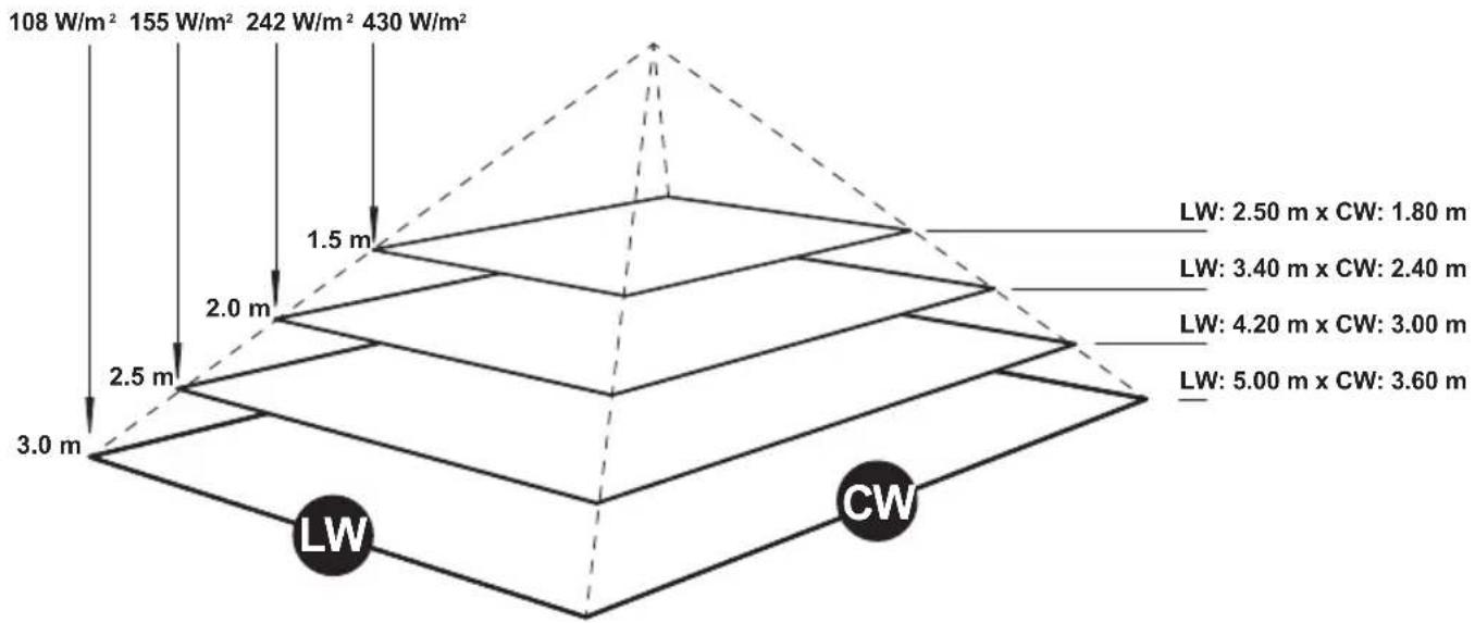
geo
| Depth (m) | Total Water (W/m²) | Lw (m) | CW (m) | |-----------|-------------------|--------|--------| | 1 | 108 | 2.50 | 1.80 | | 2 | 155 | 3.40 | 2.40 | | 3 | 242 | 4.20 | 3.00 | | 4 | 430 | 5.00 | 3.60 |D3 - 2000 W
maximale Leistung
①
②
Wärmefläche
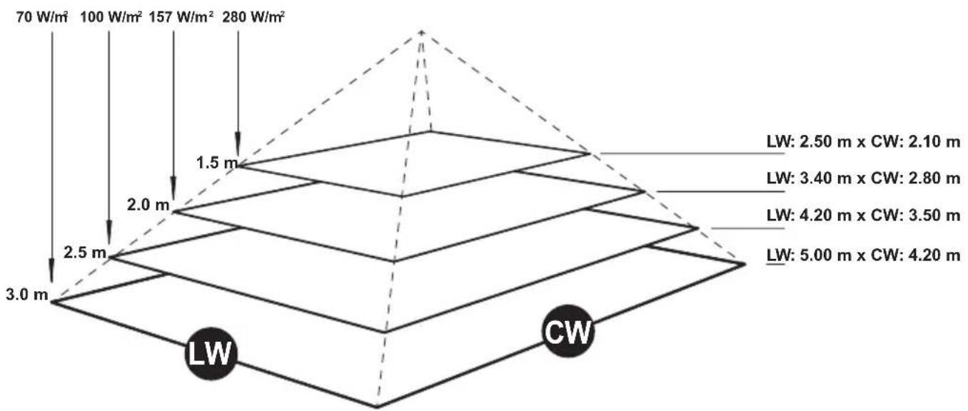
geo
| Depth (m) | Lw (W/m²) | CW (W/m²) | |-----------|-----------|-----------| | 3.0 | 70 | 100 | | 2.5 | 100 | 157 | | 2.0 | 157 | 280 | | 1.5 | 280 | — |01/2021
ETHERMA
Elektrowärme GmbH
Landesstraße 16
A-5302 Henndorf
Tel.: +43 (0) 6214 | 76 77
Fax: +43 (0) 6214 | 76 66
Web: www.ethema.com
Mail: office@etherma.com