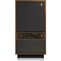
VQ 100 - Speaker TANNOY - Free user manual and instructions
Find the device manual for free VQ 100 TANNOY in PDF.
Download the instructions for your Speaker in PDF format for free! Find your manual VQ 100 - TANNOY and take your electronic device back in hand. On this page are published all the documents necessary for the use of your device. VQ 100 by TANNOY.
USER MANUAL VQ 100 TANNOY
Important Safety Instructions LEGAL DISCLAIMER LIMITED WARRANTY Terminals marked with this symbol carry electrical current of sucient magnitude to constitute risk of electric shock. Use only high-quality professional speaker cables with ¼" TS or twist-locking plugs pre-installed. Allother installation or modication should be performed only by qualiedpersonnel. This symbol, wherever it appears, alertsyou to the presence of uninsulated dangerous voltage inside the enclosure-voltage that may be sucient to constitute a risk ofshock. This symbol, wherever it appears, alertsyou to important operating and maintenance instructions in the accompanying literature. Please read the manual. Caution To reduce the risk of electric shock, donot remove the top cover (or the rear section). No user serviceable parts inside. Refer servicing to qualied personnel. Caution To reduce the risk of re or electric shock, do not expose this appliance to rain and moisture. The apparatus shall not be exposed to dripping or splashing liquids and no objects lled with liquids, suchas vases, shall be placed on the apparatus. Caution These service instructions are for use by qualied service personnel only. Toreduce the risk of electric shock do not perform any servicing other than that contained in the operation instructions. Repairs have to be performed by qualied servicepersonnel.
1. Read these instructions.
2. Keep these instructions.
3. Heed all warnings.
4. Follow all instructions.
5. Do not use this apparatus near water.
6. Clean only with dry cloth.
7. Do not block any ventilation openings. Install in
accordance with the manufacturer’s instructions.
8. Do not install near any heat sources such as
radiators, heat registers, stoves, or other apparatus (including ampliers) that produce heat.
9. Do not defeat the safety purpose of the polarized
or grounding-type plug. A polarized plug has two blades with one wider than the other. A grounding-type plug has two blades and a third grounding prong. The wide blade or the third prong are provided for your safety. Ifthe provided plug does not t into your outlet, consult an electrician for replacement of the obsolete outlet.
10. Protect the power cord from being walked on or
pinched particularly at plugs, convenience receptacles, and the point where they exit from the apparatus.
11. Use only attachments/accessories specied by
12. Use only with the
cart, stand, tripod, bracket, or table specied by the manufacturer, orsold with the apparatus. When a cart is used, use caution when moving the cart/apparatus combination to avoid injury from tip-over.
13. Unplug this apparatus during lightning storms or
when unused for long periods of time.
14. Refer all servicing to qualied service personnel.
Servicing is required when the apparatus has been damaged in any way, such as power supply cord or plug is damaged, liquid has been spilled or objects have fallen into the apparatus, the apparatus has been exposed to rain or moisture, does not operate normally, or has beendropped.
15. The apparatus shall be connected to a MAINS socket
outlet with a protective earthing connection.
16. Where the MAINS plug or an appliance coupler is
used as the disconnect device, the disconnect device shall remain readily operable.
17. Correct disposal of this
product: This symbol indicates that this product must not be disposed of with household waste, according to the WEEE Directive (2012/19/EU) and your national law. This product should be taken to a collection center licensed for the recycling of waste electrical and electronic equipment (EEE). The mishandling of this type of waste could have a possible negative impact on the environment and human health due to potentially hazardous substances that are generally associated with EEE. At the same time, your cooperation in the correct disposal of this product will contribute to the ecient use of natural resources. For more information about where you can take your waste equipment for recycling, please contact your local city oce, or your household waste collection service.
18. Do not install in a conned space, such as a book
case or similar unit.
19. Do not place naked ame sources, such as lighted
candles, on the apparatus.
20. Please keep the environmental aspects of battery
disposal in mind. Batteries must be disposed-of at a battery collection point.
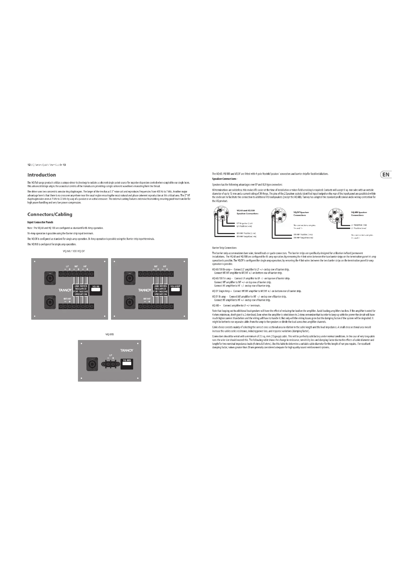
OGRANICZONA GWARANCJA12 VQ Series Quick Start Guide 13 Introduction The VQ full range products utilize a unique driver technology to radiate a coherent single point source for superior dispersion control when coupled to our single horn. This advanced design aligns the acoustical centres of the transducers providing a single coherent wavefront emanating from the throat. The driver uses two concentric annular ring diaphragms. The larger of the two has a 3.5” voice coil and reproduces frequencies from 400 Hz to 7 kHz. Another major advantage here is that there is no crossover anywhere near the vocal region ensuring the most natural and phase coherent reproduction at this critical area. The 2” HF diaphragm takes over at 7 kHz to 22 kHz by way of a passive or an active crossover. The external casting features extensive heatsinking ensuring good heat transfer for high power handling and very low power compression. Connectors/Cabling Input Connector Panels Note : The VQ 60 and VQ 100 are congured as standard for Bi-Amp operation. Tri-Amp operation is possible using the Barrier strip input terminals. The VQ DF is congured as standard for single amp operation. Bi-Amp operation is possible using the Barrier strip input terminals. The VQ MB is congured for single amp operation. VQ 60 / 100 VQ DF VQ MB The VQ 60, VQ 100 and VQ DF are tted with 4-pole Neutrik Speakon´ connectors and barrier strip for xed installations. Speakon Connections - Speakon has the following advantages over EP and XLR type connectors: All terminations are solderless; this makes life easier at the time of installation or when eld servicing is required. Contacts will accept 6 sq. mm wire with an outside diameter of up to 15 mm and a current rating of 30 Amps. The pins of the 2 Speakon sockets identied input/output on the rear of the input panel are paralleled within the enclosure to facilitate the connection to additional VQ loudspeakers (except the VQ MB). Tannoy has adopted the standard professional audio wiring convention for the VQ product. Barrier Strip Connections The barrier strip accommodates bare wire, tinned leads or spade connectors. The barrier strips are specically designed for utilization in xed/permanent installations. The VQ 60 and VQ 100 are congured for Bi-amp operation; by removing the 4 link wires between the two barrier strips on the termination panel tri-amp operation is possible. The VQ DF is congured for single amp operation; by removing the 4 link wires between the two barrier strips on the termination panel bi-amp operation is possible. VQ 60/100 Bi-amp – Connect LF amplier to LF +/- on top row of barrier strip. Connect MF/HF amplier to MF/HF +/- on bottom row of barrier strip. VQ 60/100 Tri-amp – Connect LF amplier to LF +/- on top row of barrier strip. Connect MF amplier to MF +/- on top row of barrier strip. Connect HF amplier to HF +/- on top row of barrier strip. VQ DF Single Amp – Connect MF/HF amplier to MF/HF +/- on bottom row of barrier strip. VQ DF Bi-amp – Connect MF amplier to MF +/- on top row of barrier strip. Connect HF amplier to HF +/- on top row of barrier strip. VQ MB – Connect amplier to LF +/- terminals. Note that looping out to additional loudspeakers will have the eect of reducing the load on the amplier. Avoid loading ampliers too low. If the amplier is rated for 4 ohms minimum, don't give it a 2 ohm load. Even when the amplier is rated down to 2 ohms remember that in order to keep up with the power the circuit will have much higher current than before and the wiring will have to handle it. Not only will the wiring losses grow but the damping factor of the system will be degraded. It might be better to run separate cables from the amp to the speakers or divide the load across two amplier channels. Cable choice consists mainly of selecting the correct cross sectional area in relation to the cable length and the load impedance. A small cross sectional area would increase the cables series resistance, inducing power loss, and response variations (damping factor). Connectors should be wired with a minimum of 2.5 sq. mm (12 gauge) cable. This will be perfectly satisfactory under normal conditions. In the case of very long cable runs the wire size should exceed this. The following table shows the change in resistance, sensitivity loss and damping factor due to the eects of cable diameter and length for two nominal impedance loads (4 ohms & 8 ohms). Use this table to determine a suitable cable diameter for the length of run you require. For resultant damping factor, values greater than 20 are generally considered adequate for high quality sound reinforcement systems. VQ 60 and VQ 100 Speakon ConnectionsLF Negative (-ve)LF Positive (+ve)MF/HF Positive (+ve) MF/HF Negative (-ve)VQ DF SpeakonConnectionsNo connections on pins1+ and 1-MF/HF Negative (-ve)MF/HF Positive (+ve)VQ MB SpeakonConnectionsLF Negative (-ve)LF Positive (+ve)No connections on pins2+ and 2-14 VQ Series Quick Start Guide 15 Polarity Checking It is most important to check the polarity of the wiring before the speaker system is own. A simple method of doing this without a pulse based polarity checker for LF units is as follows: Connect two wires to the +ve and -ve terminals of a PP3 battery. Apply the wire which is connected to the +ve terminal of the battery to the speaker cable leg which you believe to be connected to pin 1+ of the speaker connector and likewise the -ve leg of the battery to pin 1-. If you have wired it correctly the LF drive unit will move forward, indicating the wiring is correct. All that remains now is to connect the +ve speaker lead to the +ve terminal on the amplier and the -ve lead to the -ve terminal on the amplier. If however the LF driver moves backwards, the input connections need to be inverted. There are also commercially available polarity checkers that can be used (IviePAL™, NTI™). If you are commissioning a system using a spectrum analyzer such as SMAART™, SYSTUNE™, CLIO™, MLSSA™ by checking the impulse response for the rst positive swing. Be sure that EQ and crossover ltering has been removed before checking. If problems are encountered, inspect the cable wiring in the rst instance. If you are using ampliers from more than one manufacturer, check the polarity at the ampliers as well as the loudspeakers. Amplication & Power Handling As with all professional loudspeaker systems, the power handling is a function of voice coil thermal capacity. Care should be taken to avoid running the amplier into clip (clipping is the end result of overdriving any amplier). Damage to the loudspeaker will be sustained if the amplier is driven into clip for any extended period of time. Headroom of at least 3dB should be allowed. When evaluating an amplier, it is important to take into account its behavior under low impedance load conditions. A loudspeaker system is highly reactive and with transient signals it can require more current than the nominal impedance would indicate. Generally a higher power amplier running free of distortion will do less damage to the loudspeaker than a lower power amplier continually clipping. It is also worth remembering that a high powered amplier running at less than 90% of output power generally sounds a lot better than a lower power amplier running at 100%. An amplier with insucient drive capability will not allow the full performance or the loudspeaker to be realized. It is important when using dierent manufacturers ampliers in a single installation that the have very closely matched gains, the variation should be less than +/- 0.5 dB. This precaution is important to the overall system balance when only a single active crossover is being used with multiple cabinets; it is therefore recommended that the same ampliers be used throughout. On the specications pages you will nd the VQ loudspeakers power handling capacity quoted in three categories:- Average (RMS), Programme, & Peak We recommend using the programme power listed in the loudspeaker specications to choose the correct amplier. To realize the VQ loudspeakers full potential, the ampliers rated continuous power should be equal to the loudspeakers programme power at its nominal impedance. Loudspeaker Management Systems Tannoy VQ series loudspeakers are designed to be used with an electronic signal processor which provides crossover, equalization, delay and dynamic functions. We strongly recommend LabGruppen PLM+ or D Series with factory presets from LAKE load library. LAKE LM26/44 DSP using the same factory presets from LAKE load library coupled with LabGruppen C series or FP+ series using models with appropriate output power for the VQ cabinets selected is also recommended. LabGruppen CAFE software provides a comprehensive solution for selecting the best possible combination of PLM+ or D series products to all Tannoy loudspeaker products, allowing users to have precise technical data of power delivery, power draw, thermal output, cable infrastructure requirements and BOM calculator. For more information about LAKE and LabGruppen products, please go to www.lakeprocessing.com or www.labgruppen.com. Rigging & Suspension The VQ hardware covered in this guide has been designed to oer quick, simple, and secure solutions for mounting specic VQ loudspeakers. This hardware has been designed and manufactured with a high safety load factor for its specic role. To ensure the safest possible use of the hardware covered in this guide, it must be assembled in strict accordance with the instructions specied. The information in these manuals relating to the assembly and the safe use of these accessories must be understood and followed. The installation of VQ loudspeakers using the dedicated hardware should only ever be carried out by fully qualied installers, in accordance with all the required safety codes and standards that are applied at the place of installation. WARNING: As the legal requirements for ying change from country to country, please consult your local safety standards oce before installing any product. We also recommend that you thoroughly check any laws and bylaws prior to commencing work. VQ hardware has been designed for use with VQ series loudspeakers only, and is not designed or intended for use with any other Tannoy Commercial products, or any other devices from other manufacturers. Using Tannoy Professional hardware for any purpose other than that indicated in this guide is considered to be improper use. Such use can be very dangerous as overloading, modifying; assembling in anyway other than that clearly stated in the manual, or damaging the VQ hardware will compromise safety. The component parts of any VQ hardware device must only be assembled using the accessory kits supplied and in strict compliance with the user manual. The use of other accessories or non-approved methods of assembly may result in an unsafe hardware system by reducing the load safety factor. Welding, or any other method of permanently xing hardware components together or to the integral xing points in the cabinet should never be used. Whenever a VQ loudspeaker is xed to a surface using a VQ hardware device, the installer must ensure that the surface is capable of safely and securely supporting the load. The hardware employed must be safely, securely, and in accordance with the manual, attached both to the loudspeaker and also to the surface in question, using only the xing holes provided as standard and covered in the manual. Secure xings to the building structure are vital. Seek help from architects, structural engineers or other specialists if in any doubt. All loudspeakers own must, be provided with an independent, correctly rated and securely attached secondary safety – in addition to the principle hardware device. This secondary safety must prevent the loudspeaker from dropping more than 150 mm (6") should the principle hardware device fail. WARNING: Do not under any circumstances use a loudspeaker's handles to support the weight of the loudspeaker except for their intended use: hand carrying. The handles are not rated to support the load of the loudspeaker for temporary or permanent installation. The VQ range of loudspeakers is intended to be suspended or ground-stacked. This section details how to physically congure VQ yware and arrays. The following are the recommended methods for most situations. Specic situations may require other methods. It is the user's responsibility to determine the viability and safety for alternate methods and implement them accordingly. Cable Run Diameter of conductor Cable Resistance Wire Loss (dB) Damping Factor* m ft mm awg ohm 4ohm Load 8ohm Load 4ohm Load 8ohm Load 5 16 1.5 mm
*The resulting damping factor gures are derived using a good quality professional amplier VQ Series Recommended Amplier Power VQ60/100 Power Requirement Low Frequency Passive MF/HF Mid Frequency High Frequency 2000 W into 4 ohms 400 W into 8 ohms 400 W into 8 ohms 200 W into 8 ohms VQ DF Passive MF/HF Mid Frequency High Frequency 400 W into 8 ohms 400 W into 8 ohms 200 W into 8 ohms VQ MB 2000 W into 4 ohms16 VQ Series Quick Start Guide 17 Flying A Single VQ Cabinet Using Eyebolts The simplest method of ying a single VQ cabinet is with a pair of M10 shoulder eyebolts on the top, using a third eyebolt on the rear of the cabinet to tilt the cabinet. VQ Flying Bracket (Single Point Hang Flying Bracket) For safe, exible and simple ying, the VQ Flying bracket is designed to suspend the VQ cabinet from a single pivot point. This allows precise adjustment of aiming angles with the cabinet in situ. The own VQ loudspeaker must be provided with an independent, correctly rated and securely attached secondary safety – in addition to the principle hardware device. This secondary safety must prevent the loudspeaker from dropping more than 150mm (6”) should the principle hardware device fail. Note: All xings should be thread-locked and torqued to 25 Nm.
1. Register online. Please register your new
Music Tribe equipment right after you purchase it by visiting musictribe.com. Registering your purchase using our simple online form helps us to process your repair claims more quickly and eciently. Also, read the terms and conditions of our warranty, if applicable.
2. Malfunction. Should your Music Tribe
Authorized Reseller not be located in your vicinity, you may contact the Music Tribe Authorized Fulller for your country listed under “Support” at musictribe.com. Should your country not be listed, please check if your problem can be dealt with by our “Online Support” which may also be found under “Support” at musictribe.com. Alternatively, please submit an online warranty claim at musictribe.com BEFORE returning the product.
3. Power Connections. Before plugging the
unit into a power socket, please make sure you are using the correct mains voltage for your particular model. Faulty fuses must be replaced with fuses of the same type and rating without exception.