VC750 E - Multimeter VOLTCRAFT - Free user manual and instructions
Find the device manual for free VC750 E VOLTCRAFT in PDF.

User questions about VC750 E VOLTCRAFT
0 question about this device. Answer the ones you know or ask your own.
Ask a new question about this device
Download the instructions for your Multimeter in PDF format for free! Find your manual VC750 E - VOLTCRAFT and take your electronic device back in hand. On this page are published all the documents necessary for the use of your device. VC750 E by VOLTCRAFT.
USER MANUAL VC750 E VOLTCRAFT
GB Operating Instructions
VC-750E AC/DC Clamp Multimeter
Item No. 1500205 Page 39 - 73
F Mode d'emploi
www.business.conrad.at
natural_image
Technical line drawing of a handheld device with two labeled buttons and a central display panel (no text or symbols beyond basic labels)text_image
Hertz% G 50.00 50.88 COM VOLTS 8 RCA DC DC DC DC DC DC DC DC DC DC DC DC DC DC DC DC DC DC DC DC DC DC DC DC DC DC DC DC DC DC DC DC DC DC DC DC DC DC DC DC DC DC DC DC DC DC DC DC DC DC DSCA VOLTS 8 RCA DC DC DC DC DC DC DC DC DC DC DC DC DC DC DC DC DC DC DC DC DC DC DC DC DC DC DC DC DC DC DC DC DC DC DC DC DC
text_image
Diagram of a multimeter setup with labeled components including U1, U2, and digital display showing voltage reading.- Introduction......41
- Product description 41
- Intended use....42
- Delivery content......43
- Safety instructions 43
- Explanation of symbols....45
- Product overview 46
- Buttons and control knob 47
- Display and symbols....48
- Inserting and replacing batteries....50
a) Notes on batteries 50
b) Inserting/changing the batteries 50
- Switching on and off 51
a) Turning on and off....51
b) Automatic switch-off feature ....51
- Backlight 51
- Generic functions....52
a) Analogue bar graph....52
b) RANGE – Manually selecting the measuring range 52
c) MAX/MIN function....53
d) REL function....53
e) HOLD function....53
- Measuring/Testing – Observe unconditionally ....54
a) Safety instructions relating to measuring/testing....54
b) Warn signals....54
- Measuring – Voltage....54
a) Measuring procedure....54
b) Direct voltage (V/DC) 55
c) Alternating voltage (V/AC) 55
d) Alternating voltage (V/AC) – Low Pass Filter 55
e) AC + DC voltage....55
f) LoZ alternating voltage 55
- Measuring – Current 56
a) Introduction....56
b) Measuring procedure....56
c) Alternating current (A \~)....56
d) Direct current (A ^--- ) 57
e) AC + DC current 57
f) Surge/Inrush current....57
g) Split display - AC/DC 58
17. Measuring – Signal current μA....58
a) Introduction....58
b) Measuring procedure....58
c) Direct current ( A =) 59
d) Alternating current ( A^ )....59
18. Measuring – Frequency (electronic) 59
- Measuring – Resistance 60
- Measuring – Capacitance 61
- Measuring – Temperature....62
a) Introduction....62
b) Measuring procedure....62
22. Testing – Diode....63
- Testing – Continuity 63
- Testing - Motor direction (3-phase) 64
a) Introduction....64
b) Special notes....64
c) Testing procedure....64
25. Cleaning and maintenance....65
a) General information....65
b) Cleaning 65
26. Disposal....66
- Troubleshooting 66
- Technical data....67
a) Direct voltage (V/DC)....68
b) Alternating voltage (V/AC) 68
c) AC + DC voltage....69
d) Direct current (μA/DC) 69
e) Alternating current (μA/AC) 69
f) Alternating current (A/AC, clamp measurements) 70
g) AC + DC current....70
h) Resistance....71
i) Acoustic continuity tester....71
j) Capacity....72
k) Diode test 72
I) Frequency "Hz" (electronic) 72
m) Frequency "Hz" (electrical) 73
n) Temperature 73
1. Introduction
Dear customer,
Thank you for purchasing this product.
This product complies with statutory national and European regulations.
For safety reasons, always follow the instructions in this manual.

These operating instructions are part of this product. They contain important information on setting up and using the product. Please consider this if you pass on the product to a third party, and keep the operating instructions for future reference.
If there are any technical questions, please contact:
International: www.conrad.com/contact
United Kingdom: www.conrad-electronic.co.uk/contact
2. Product description
The multimeter displays measurements on a digital display. The multimeter has 6000 counts (count = smallest display value). The true RMS value is used when measuring AC voltages and currents.
To prolong the battery life, the multimeter switches off automatically after 15 minutes of inactivity. The automatic switch-off function can be manually disabled.
The meter can be used for DIY, professional, and industrial purposes up to CAT IV. The rubber seal gives the multimeter a robust design and enables it to withstand falls from up to 2 m. The multimeter is also dust and splash-proof (IP54). Before replacing the batteries or fuse, check that the battery compartment seal is clean and intact. Remove dirt and dust with a thin cotton swab. The seal must not be damaged. Do not apply grease or other sealants, as this may affect the safety of the device.
Protective caps may be attached to the test lead plugs. Remove these before inserting the test leads into the multimeter.
3. Intended use
Measures and displays electrical parameters in measurement category CAT IV (up to 600V). Complies with the EN 61010-1 standard and all lower categories.
The product supports measurement and testing of:
- Measures DC voltages up to 600 V (10 MΩ impedance)
- Measures AC voltages up to 600 V (10 MΩ impedance)
- Measures AC voltages up to 600 V with a low impedance (300 kΩ)
• Measures direct and alternating currents up to 2000 μA (signal currents) - Contactless measurement of direct and alternating currents up to 600 A
• Frequency measurement:
- Electronic: 10 Hz – 40 MHz (max. 30 Vrms)
- Electrical: 40 – 400 Hz (30 – 600 Vrms)
- Duty cycle
• Measures capacitance up to 60 mF
• Measures resistance up to 60 MΩ
• Measures temperatures from -40 to +1000 °C.
• Continuity test (<10 Ω acoustic) - Diode test
- Low pass filter (600 V)
- Split display for voltage/current
- AC + DC Current/Voltage
- 3-phase rotation indicator for the voltage range 80–600 V/AC
Use the control knob to select the measuring mode.
Effective (True RMS) measurements are displayed when measuring AC voltages/currents with a frequency of up to 400 Hz.
The A current measurement input is protected against overload by a resettable fuse (PTR). The voltage in the measuring circuit may not exceed 600 V.
The device switches off automatically after 15 minutes if no buttons are pressed. This prevents the battery from draining. This automatic switch-off function can be disabled.
Do not use the multimeter when the battery compartment is open.
The multimeter has an IP54 protection rating, meaning that it is dust and splash-proof. However, do not use the multimeter when it is wet or damp.
Do not take measurements in potentially explosive areas, damp rooms or adverse environmental conditions. Adverse conditions include: Moisture or high humidity, dust and flammable gases, vapours or solvents, thunderstorms, and strong electromagnetic fields.
For safety reasons, only use test leads and accessories that conform to the multimeter specifications.
The device must only be used by people who have the necessary physical and mental skills to ensure that measurements are taken safely.
The user must also be familiar with regulations on taking measurements and the possible hazards. The use of personal protective equipment is recommended.
Any use other than that described above may damage the product and cause additional hazards such as a short circuit, fire, or electric shock. The product must not be modified or reassembled!
Read the operating instructions carefully and keep them in a safe place for future reference.

Always observe the safety information in these instructions.
4. Delivery content
- Clamp multimeter
- 3 x AAA batteries
- 2 x CAT IV safety test leads
• Temperature probe (-40 to +250 °C type K with banana plug) - Safety instructions
- Operating instructions (on CD)
Up-to-date operating instructions
Download the latest operating instructions via the link www.conrad.com/downloads or scan the QR code. Follow the instructions on the website.
5. Safety instructions
Read the operating instructions and safety information carefully. If you do not follow the safety instructions and information on proper handling in this manual, we assume no liability for any resulting personal injury or damage to property. Such cases will invalidate the warranty/guarantee.
• This device was shipped in a safe condition.
- To ensure safe operation and avoid damaging the product, always observe the safety information and warnings in these instructions.
- For safety and approval reasons, do not attempt to convert and/or modify the device.
- Consult a technician if you are not sure how to use or connect the device.
- Measuring instruments and their accessories are not toys and should be kept out of the reach of children.
- Always comply with accident prevention regulations for electrical equipment when using the product in industrial facilities.
- In schools, educational facilities, hobby and DIY workshops, measuring devices must be operated under the responsible supervision of qualified personnel.
- Before each measurement, always make sure that the meter is set to the correct measurement mode.
- When using measuring probes without protective caps, measurements between the multimeter and the earth potential must not exceed the CAT II measurement category.
• Always remove the test probes from the measured object before changing the measurement mode.
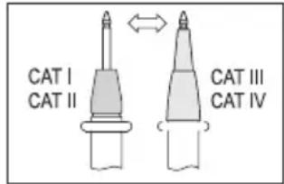
- When taking CAT III and CAT IV measurements, the cover caps must be placed on the probe tips (max. length of exposed contacts = 4 mm) to avoid accidental short circuits. These are supplied with the device.
- The voltage between the multimeter connection points and earth must never exceed 600 V DC/AC in CAT IV.
text_image
CAT I CAT II CAT III CAT IV- Exercise particular caution when dealing with voltages exceeding 33 V/AC or 70 V/DC. Touching electrical conductors at these voltages may result in a fatal electric shock.
- To prevent an electric shock, do not touch the measuring points when taking measurements, either directly or indirectly. When taking measurements, do not grip beyond the grip markings on the multimeter and test probes.
- Check the measuring device and test leads for signs of damage before each measurement. Never take measurements if the protective insulation is damaged (torn, missing, etc.). The measuring cables come with a wear indicator. If a cable is damaged, a second layer of insulation will become visible (the second layer of insulation is a different colour). If this happens, discontinue use and replace the measurement accessory.
- Do not use the multimeter before, during or after a storm (risk of electric shock / power surge). Ensure that your hands, shoes, clothes, the floor, circuit and circuit components are dry
- Avoid using the device in the immediate vicinity of:
- Strong magnetic or electromagnetic fields
- Transmitting antennas or HF generators.
- These may distort the measurements.
- If you have reason to assume that safe operation is no longer possible, disconnect the device immediately and prevent it from being used unintentionally. Safe operation can no longer be guaranteed if:
- There are signs of damage
- The device does not function properly
- The device was stored under unfavourable conditions for a long period of time
- The device was subjected to rough handling during transport
- Do not switch the device on immediately after it has been brought from a cold room into a warm one. The condensation generated may destroy the product. Leave the device switched off and allow it to reach room temperature.
- Do not leave packaging material unattended, as it may become dangerous playing material for children.
- Observe the safety information in the individual chapters.
6. Explanation of symbols

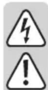
The symbol with the lightning in the triangle indicates that there is a risk to your health, e.g. due to an electric shock.

The lightning symbol in the square permits current measurements on uninsulated, hazardous active conductors and warns of the possible hazards. Personal protective equipment must be used.

This symbol is used to highlight important information in these operating instructions. Always read this information carefully.

This symbol indicates special information and advice on how to use the product.

This product has been CE tested and complies with the necessary European guidelines.

Protection class 2 (double or reinforced insulation, protective insulation)
IP54 Dust- and splash-proof.
CAT I Measurement Category I: For measuring circuits of electrical and electronic equipment that is not directly supplied with a mains voltage (e.g. battery-operated devices, safety extra-low voltage systems, and signal/control voltages). In the future, this category will be renamed CAT 0 or 0.
CAT II Measurement Category II: For measuring electrical and electronic devices that are directly supplied with a mains voltage via a mains plug. This category also includes all lower categories (e.g. CAT I for measuring signal and control voltages).
CAT III Measurement Category III: For measuring circuits of installations in buildings (e.g. mains sockets or sub-distributions). This category also includes all lower categories (e.g. CAT II for measuring electrical devices). Measuring in CAT III is only permitted with test prods that are covered with caps or that have a maximum exposed contact length of 4 mm.
CAT IV Measurement Category IV: For measuring at the origin of a low-voltage installation (e.g. mains distribution, electricity provider's transfer points to homes) and outdoors (e.g. when conducting tasks on underground cables or overhead lines). This category also includes all smaller categories. Measuring in CAT IV is only permitted with test prods that are covered with caps or that have a maximum exposed contact length of 4 mm.

Earth potential
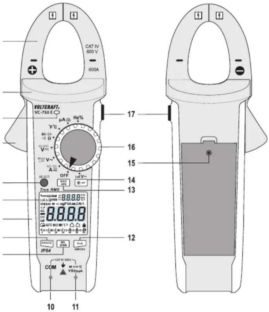
7. Product overview
text_image
CAT IV 600 V 600A VOLTCRAFT. VC-750 E µA ≈ Hz% °F°C AC+DC V~ Max+V~ AC-DC A SELECT OFF MAX MIN Lst V~ True RMS Temp+123±123 Lst Δ Φ=123 Unlstr H + mgFVAωΩR% 8.8.8.8 AC DC AUTO MAX NH C F RANGE IP54 RRL ZERO V±A INRUSH CAT B/600V COM M +P+C VΩHz μA 10 11 17 16 15 14 13 121 Current clamp
2 Grip area
3 Light sensor
4 Opening lever
5 SELECT button
6 Display
7 Soft rubber seal
8 RANGE button
9 REL/ZERO button
10 COM test socket (Black)
(Reference potential, "negative potential")
11 Test Socket (Red)
("Positive potential" for direct voltage)
12 V+A/INRUSH button
13 MAX/MIN button
14 - button
15 Screw for battery compartment
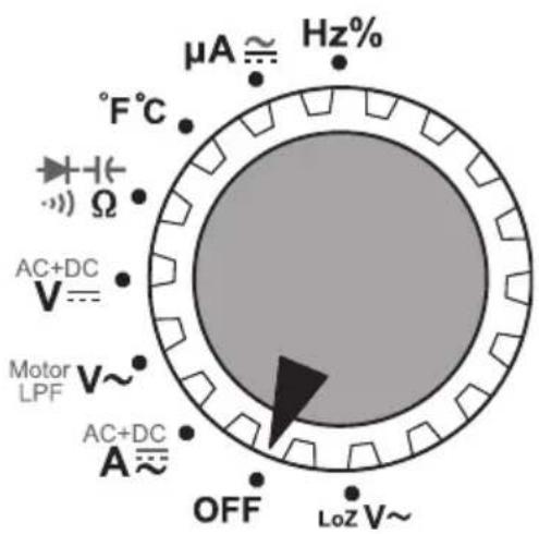
16 Control knob for selecting the measuring mode
17 Button
8. Buttons and control knob
| Button Function | |
 | Change measuring range |
 | Enable reference value measurement |
 | Trigger split display in < A or < > made |
 | Switch modes (see red/black icons on control dial) |
 | Display maximum/minimum reading |
 | Disable automatic backlight |
 | Fix current reading on display |
text_image
μA ≈ Hz% °F°C Ω AC+DC V= Motor LPF V~ AC+DC A≈ OFF LoZ V~Use the control knob (16) to select a measuring mode/range. Automatic range selection [AUTO] is enabled in modes:
$$ - H z \% / ^ {\circ} F ^ {\circ} C / \Omega / + V = V \sim A \sim A = $$
This means that the appropriate measurement range will be selected automatically.
To select the modes marked in red, press the SELECT button (5) (e.g. to switch from resistance to continuity test). Some modes require different procedures, which are described in the corresponding sections.
→ References to the control knob positions are indicated by
Example: Select < > mode.LoZ V\~
9. Display and symbols
The display (6) contains the following symbols:
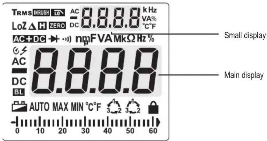
text_image
TRMS INRUSH LO AC 8.8.8.8 kHz LoZ △ H ZERO DC 0.8.8.8 VA% AC+DC → + ·) nmF VAMkΩ Hz % AC 8.8.8.8 DC BL AUTO MAX MIN °C°F 3 2 3 2 - 0 10 20 30 40 50 60 Small display Main displaySymbol Meaning/Function
TRMS True root mean square
Diode test
Acoustic continuity tester
V Volt (unit of electrical voltage)
μ Micro
A Ampere (unit of electrical current)
n Nano
m Milli
F Farad (unit of electrical capacity)
M Mega
k Kilo
Ω Ohm (unit of electrical resistance)
Hz Hertz (unit of frequency)
°C Degrees Celsius (unit of temperature)
°F Degrees Fahrenheit (unit of temperature)
8.8.8 Measured value
3-phase rotation direction indicator ("clockwise")
3-phase rotation direction indicator ("anticlockwise")
BL Backlight enabled
Lock icon for phase detection (flashing = detection mode, constant = phase detected)
▲ Relative value measurements (=reference value measurement)
MIN Minimum value
MAX Maximal value
AUTO Automatic measurement range is enabled
Automatic shut-off is enabled
Low battery indication
H Hold function is enabled
Warning symbol for dangerous voltage (with warning sound when the measuring range is exceeded)
DC Direct current DC
- Polarity indicator for current flow direction (negative pole)
AC Alternating current AC
LoZ Low impedance
% Duty cycle representation in mode Hz%
AC+DC Voltage/Current representation in form of (AC)^2+(DC)^2
ZERO Zero mode
INRUSH Inrush current measurement enabled
Low Pass Filter in LPF mode
Analogue display scale
OL Overload indicator
→ References to symbols in the display are indicated by [ symbols ] throughout the manual. Symbols which are displayed but not directly relevant to described functions are not mentioned explicitly.
Example: [ TV will show in the display.
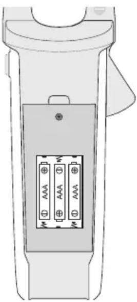
10. Inserting and replacing batteries
The multimeter is powered by three AAA batteries. Insert new batteries before using the multimeter for the first time or when the low battery indicator appears on the display. Replace the batteries immediately to prevent inaccurate measurements.

Never use the multimeter when the battery compartment is open, as this may cause a fatal electric shock.
The multimeter casing is designed so that you can only access the battery compartment. This makes the multimeter safer and easier to use.
a) Notes on batteries
- Do not leave empty batteries in the device. Even batteries protected against leaking may corrode and destroy the device or release chemicals that are detrimental to your health.
- Do not leave batteries unattended, as there is a risk that they may be swallowed by children or pets. If a battery is swallowed, seek immediate medical advice.
- To prevent the batteries from leaking, remove them from the multimeter if you are not going to use the device for an extended period of time.
- Leaking or damaged batteries may cause acid burns if they come into contact with your skin. Always use protective gloves when handling leaking or damaged batteries.
- Do not short-circuit batteries or throw them into open flames.
- Do not attempt to recharge or dismantle disposable batteries, as this may cause an explosion.

The following battery is suitable for use in the multimeter:
Order no. 652278 (3 batteries are required).
Only use alkaline batteries – alkaline batteries are more powerful and have a longer lifespan.
b) Inserting/changing the batteries
- Switch the multimeter off by turning the control knob (16) into the
position. - Disconnect all test leads and remove the current clamp from all circuits.
- Loosen the screw on the battery compartment cover (15) using a suitable screwdriver.
- Remove the battery compartment cover.
- When removing the battery compartment cover, check the rubber seal for dirt and clean it if necessary. This ensures that the multimeter remains dust- and splash-proof.
- 3 new AAA-size batteries are required. Remove the used batteries (if any) and replace the used batteries with new ones of the same type. Insert the new batteries into the battery compartment in the correct polarity.
-
Do not use 1.2 V rechargeable batteries.
-
Replace the battery compartment cover and screw it in place.
-
The multimeter is now ready for use again.
natural_image
Technical line drawing of a handheld device with two labeled pins (no text or symbols beyond basic labels)11. Switching on and off
a) Turning on and off
- Make sure you have inserted batteries into the multimeter.
- The multimeter turns on when you turn the control knob into any position other than
. - When you turn the multimeter on, a short function test will be conducted and all symbols will appear on the display. The multimeter will beep when the test is complete.
- To turn the multimeter off, turn the control knob into the
position.
→ Always turn the multimeter off when it is not in use.
b) Automatic switch-off feature
The multimeter switches off automatically after 15 minutes if no buttons are pressed or the control knob is not rotated. This protects the batteries and prolongs the battery life.
- The [ ④symbol will be displayed when the automatic switch-off feature is enabled.
- The multimeter will beep 3 times approximately 1 minute before it turns off. If a button is pressed before the multimeter switches off, the multimeter will beep again in 15 minutes. You will hear a long beep when the multimeter switches off.
- To turn the multimeter back on, move the control knob or press any button.
Disabling the automatic switch-off feature
- Turn the multimeter off and hold down the SELECT button.
- Turn the control knob into a new position.
- The multimeter will switch on and the [ ] symbol will no longer be visible on the display.
- The automatic switch-off feature will remain disabled until the multimeter is turned off using the control knob.
12. Backlight
The multimeter automatically switches the backlight on and off according to the ambient brightness. The ambient brightness is measured by the light sensor (3).
- [ B1.s displayed when the automatic backlight feature is enabled.
- To prevent the backlight from switching on automatically, press the -Button (14).
- The automatic backlight feature will be automatically re-enabled the next time you turn the multimeter on.
13. Generic functions
Some measuring modes support additional functions that are summarized in this chapter.
- Enabling and disabling of generic functions (that can be turned on and off) are confirmed by a beep.
a) Analogue bar graph
The bar graph is an approximate and analogue reflection of the values the main display shows.
Depending on the selected range, the graph's accuracy differs. Study below example diagram on 60/600 A:
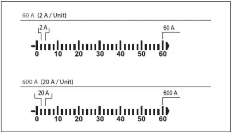
bar
| Condition | Time (A) | | --------- | -------- | | 60 A (2 A / Unit) | 2 | | 60 A | 60 | | 600 A (20 A / Unit) | 20 | | 600 A | 600 |b) RANGE – Manually selecting the measuring range
When there is interference, the multimeter may select the incorrect measuring range or alternate between two ranges.

Depending on the selected measuring mode, you can set the measuring range manually.

For a complete collection and breakdown of ranges for each function, consult the technical data section.
Manually control the range as follows:
- Press the RANGE button. The [AUTO] symbol will disappear from the display.
- Press the RANGE button again to select the next measuring range (if the highest measuring range is selected, the multimeter will go back to the lowest range). The measuring range is indicated by the position of the decimal point.
- To disable manual range selection, press and hold the RANGE button for 2 seconds. The [AUTO] symbol will be displayed to indicate that the multimeter will select the measuring range automatically.
- You can also disable manual range selection by switching to another measuring mode.
c) MAX/MIN function
This feature allows you to save and display the maximum and minimum value for a series of measurements.

Automatic range selection will be disabled. It is necessary that you manually set the range.

This feature is only available in some modes.
- Press the MAX/MIN button (13) to enable this feature.
- The maximum and minimum readings for the current set of measurements will be saved.
- Press the MAX/MIN button to switch between the maximum and minimum readings.
- The readings will be deleted when you switch to another measuring mode or turn off the multimeter.
- To disable this feature, hold down the MAX/MIN button for 2 seconds. [MAX] or [MIN] will disappear from the display and [AUTO] will be displayed.
d) REL function
The REL function sets a reference value in order to discount test lead interference during resistance measurements. The displayed reading will be reset to zero when the reference value has been set.

Automatic range selection will be disabled. It is necessary that you manually set the range.

This feature is only available in some modes.
- Press the REL/ZERO button to activate this mode. The [▲] symbol will appear on the display.
- To disable this feature, press the REL/ZERO button again or change the measuring mode.
e) HOLD function
This feature freezes the current reading on the display so that you can record it for future reference.

When testing live wires, make sure that this feature is disabled before you take any measurements, otherwise the reading will be incorrect.

This feature is only available in some modes.
- Press the H button (17) to enable this feature. The multimeter will beep and [H] will be displayed.
- To disable the hold feature, press the Button or change the measuring mode.
14. Measuring/Testing – Observe unconditionally
a) Safety instructions relating to measuring/testing
- Never exceed the maximum permitted input values. Never touch circuits or circuit components if they may carry voltages greater than 33 V/ACrms or 70 V/DC. This may cause a fatal electric shock!
- Before measuring, check the connected test leads for damage, such as cuts, tears and kinks. Never use damaged test leads, as this may cause a fatal electric shock!
- When taking measurements, do not touch any exposed areas beyond the grip markings on the test probes and the multimeter.
- Only connect the test leads that you require. For safety reasons, remove all unnecessary test leads from the device before taking a measurement.
- Measurements in circuits rated at >33 V/AC and >70 V/DC must only be made by qualified and trained personnel who are familiar with the relevant regulations and the associated hazards.
- Do not measure current on a circuit with a voltage of more than 600 V in CAT IV.
- Pay attention to the necessary safety information, regulations and protective measures for your own safety.
b) Warn signals
- As general rule, [OL] (overload) indicates that the measuring range has been exceeded (This is not true for all modes. Deviations from this rule are mentioned whenever applicable).
- When the measured voltage exceeds 30 V/AC, [ f ] will appear on the display.
- When the measured current exceeds 600 A/ACV, [⚡] will flash on the display and the multimeter beeps.
15. Measuring – Voltage
a) Measuring procedure
- Determine the type of voltage you intend to measure, then read the corresponding section in this chapter before you proceed.
- Set the multimeter to the required voltage mode as indicated in the corresponding section.
- Insert the red test lead into the ········· socket (11) and the black test lead into the COM socket (10).
- Connect the two measuring probes in parallel to the object that you want to measure (e.g. generator or circuit).
- Refer to the corresponding section on how the measured values are displayed.
- After measuring, remove the measuring leads from the measured object and turn the multimeter off.
text_image
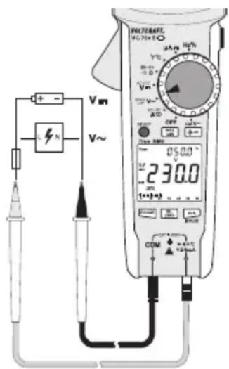
Vm V~ 230.0 COM DCP 050.0 V 1+~+3 DCP DCP DCP DCP DCP DCP DCP DCP DCP DCP DCP DCP DCP DCP DCP DCP DCP DCP DCP DCP DCP DCP DCP DCP DCP DCP DCP DCP DCP DCP DCP DCP DCP DCPb) Direct voltage (V/DC)
The V/DC voltage range has an input resistance of ≥10 M , meaning there is almost no impact on circuit performance.
- Select < V-mode. [DC V] will appear on the display.
- The main display indicates the measured voltage.
- A minus symbol indicates that the measured DC voltage is negative (or that the measuring leads are connected in the wrong polarity).
c) Alternating voltage (V/AC)
The V/AC voltage range has an input resistance of ≥10 M , meaning there is almost no impact on circuit performance.
- Select < V mode. [AC V] will appear on the display.
- The main display indicates the measured voltage.
- The small display indicates the measured frequency.
d) Alternating voltage (V/AC) – Low Pass Filter
The low pass filter intercepts voltages exceeding 1 kHz.
- Select < LPF > mode. [ AC V 10 ] will appear on the display.
- The main display indicates the measured voltage.
- The small display indicates the measured frequency.
e) AC + DC voltage
- Select < AC + DC> mode under < V > . [V AC+DC] will appear on the display.
- The main display indicates the measured voltage in form of (AC)^2 + (DC)^2
- The small display alternates between displaying the measured DC voltage and AC voltage.
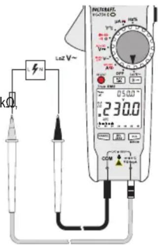
f) LoZ alternating voltage
< LoZmode allows you to measure AC voltages with a low impedance (approx. 300 kΩ). In this mode, the multimeter lowers the internal resistance to prevent 'phantom' voltage readings. As a result, the circuit is more heavily loaded than in the standard measuring mode.
The LoZ V/AC voltage range has an input resistance of <300 kΩ, which may slightly affect circuit performance.
- Select < L>ZVde. [AC V ] will appear on the display.
- The main display indicates the measured voltage.
- The small display indicates the measured frequency.
text_image
LZN LoZ V~ 05.00 230.0 COM 100mA 100mA 100mA 100mA 100mA 100mA 100mA 100mA 100mA 100mA 100mA 100mA 100mA 100mA 100mA 100mA 100mA 100mA 100mA 100mA 100 mA 10 mA 1 mA 1 mA 1 mA 1 mA 1 mA 1 mA 1 mA 1 mA 1 mA 1 mA 1 mA 1 mA 1 mA 1 mA16. Measuring – Current
a) Introduction
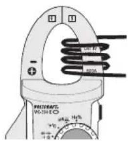
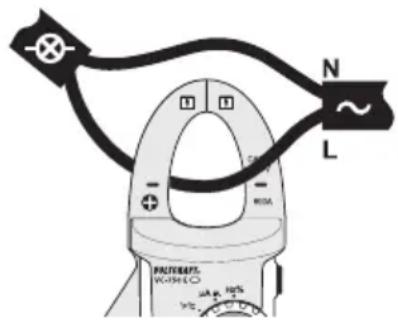
- The current is measured via the current clamp (1). The sensors in the current clamp detect the magnetic field created by current-carrying conductors.
- You can take measurements on insulated and uninsulated conductors.
- Always ensure that the conductor passes through the centre of the current clamp (pay attention to the - marks) and that the clamp is closed.
Cancellation and Addition
- Do not use the current clamp to surround more than one conductor. If the supply and return conductors (e.g. L and N) are measured, the currents will cancel each other out and no measurement will be displayed.
- If several supply conductors (e.g. L1 and L2) are measured, the currents will be added together.
Low currents
- At low currents, the conductor can be wound around one side of the current clamp to increase the total measured current.
- To obtain the correct current value, divide the measured current by the number of coils.
text_image
N L PACTURENT. VOUTLE mA R10 mA R12 mA R14 mA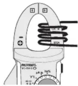
text_image
PHYCRRAFT DC-1250Ω 34A 16% + - 80Ωb) Measuring procedure
- Determine the type of current you intend to measure, then read the corresponding section in this chapter before you proceed.
- Set the multimeter to the required current mode as indicated in the corresponding section.
- The display is automatically set to zero when the current clamp is closed. If there is a strong magnetic field that affects the reading, use the relative value function ("REL").
- Press the opening lever (4) to open the current clamp.
- Surround the conductor that you want to measure and close the current clamp. Position the conductor in the middle between the two markings on the clamp.
- Refer to the corresponding section on how the measured values are displayed.
- After measuring, remove the current clamp from the measured object and turn the multimeter off.
c) Alternating current (A\~
- Select < A mode. [A AC] will appear on the display.
- The main display indicates the measured current.
- The small display indicates the measured frequency.
• The Symbol indicates a True RMS value.
d) Direct current (A—
- Select < A mode. [A DC] will appear on the display.
• The main display indicates the measured current.
e) AC + DC current
- Select < AC + DC> mode under < A > . [A AC+DC] will appear on the display.
- The main display indicates the measured current in form of (AC)^2 + (DC)^2
- The small display alternates between displaying the measured DC and AC current.
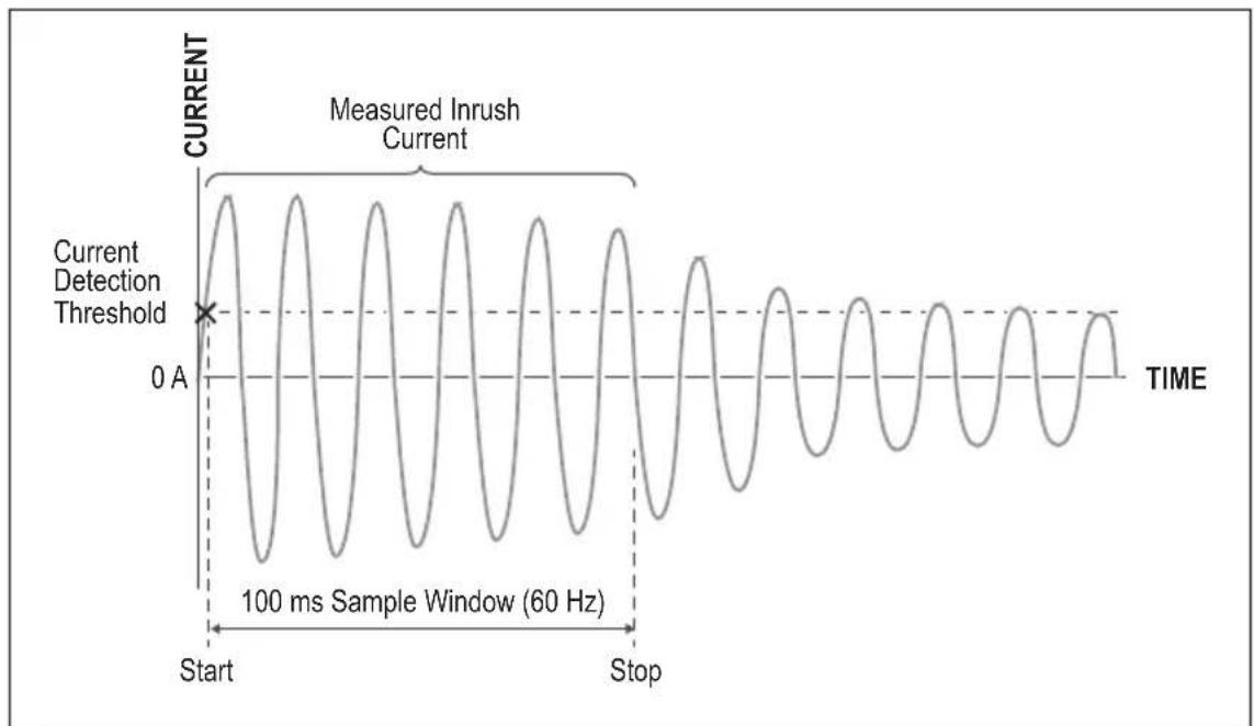
f) Surge/Inrush current
The INRUSH function facilitates the measurement of surge/inrush currents on motors.
- Select < >Amode. [ A AC ] will appear on the display.
- Long press the V+A/INRUSH button to enter the INRUSH mode. 📌 appear on the display.
- The main display indicates the measured surge/inrush current.
- The small display indicates the measured stable working current.
- Surge/inrush current is measured during the first 100 ms (see below diagram) based on the following criteria:
Range 60 A: 6 A detection threshold, max. 80 A measurement
Range 600 A: 60 A detection threshold, max. 800 A measurement
line
| Time Segment | Value | | ------------ | ----- | | Start | 0 A | | Stop | 0 A |- Long press the V+A/INRUSH button to exit surge current measurement mode.
g) Split display - AC/DC
The split display functionality allows for displaying current along with voltage.

Split displays are only possible in < and < > modes:
-
Select < >mode or < >mode:
-
Press the V+A/INRUSH button to trigger the split display. The below table summarizes the split display properties for each mode after enabling it:
| Mode Main display Small display | ||
| < A~ | Alternating current Alternating voltage | |
| < A--- | Direct current Direct voltage | |
- Press the V+A/INRUSH again to terminate split display.
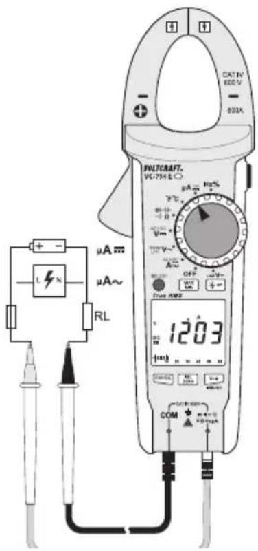
17. Measuring – Signal current μA
a) Introduction
You can use the multimeter to measure signal currents up to 2000 A.

The A current input is protected against overload with a resettable fuse. The fuse does not need to be replaced in the event of an overload. The fuse components limit the current to prevent a defect.
b) Measuring procedure
-
Determine the type of current you intend to measure, then read the corresponding section in this chapter before you proceed.
-
Set the multimeter to the required current mode as indicated in the corresponding chapter.
-
Insert the red test lead into the socket and the black test lead into the COM socket.
-
Connect the two measuring probes in parallel to the object that you want to measure (e.g. battery or circuit). The electrical circuit must be disconnected before you connect the probes.
-
Reconnect the circuit.
-
Refer to the corresponding section on how the measured values are displayed.
-
After measuring, disconnect the circuit and remove the test leads from the measured object.
-
Switch the multimeter off.
text_image
CATN 600 V 800A + - L N μA~ μA~ RL WLTCKRAFT. VC-754 E μA Hz% + - V V~ - - OFF - - + - Power AWD 1203 COM CCTIN 600 V + - + - V V V V V V V V V V V V V V V V V V V V V V V V V V V V V V V V V V V V V V V V V V V V V V V V V V Vc) Direct current ( A—
- Select < A mode. [DC A ] will appear on the display.
• The main display indicates the measured current. - A minus symbol [−] indicates that the current is flowing in the opposite direction (or that the measuring leads are connected in the wrong polarity).
d) Alternating current (μA \~
- Select < A mode. [AC A ] will appear on the display.
- The main display indicates the measured current.
• The small display indicates the measured frequency.
• The Symbol indicates a True RMS value.
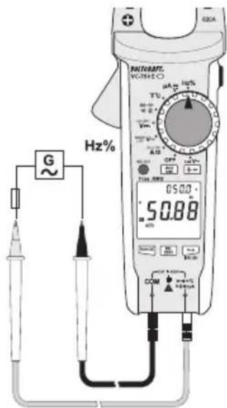
18. Measuring – Frequency (electronic)
The multimeter can be used to measure signal voltage frequencies from 10 Hz to 40 MHz. The maximum input is 30 Vrms.
- This mode is not suitable for taking measurements on mains voltages.
- For mains voltages, the frequency is measured and displayed along the voltage. Refer to the corresponding chapters.
- Observe the input specifications in the technical data.
- Select < Hz% > mode. [Hz %] will appear on the display.
- Insert the red test lead into the socket and the black test lead into the COM socket.
- Connect the two measuring probes in parallel to the object that you want to measure (e.g. signal generator or circuit).
- The main display indicates the measured frequency. The small display indicates the duty cycle in %.
- After measuring, remove the test leads from the measured object and turn the multimeter off.
text_image
G Hz% MATLABE VOUTHEO 05.00 50.88 A1 A2 OFF TUE 100 DCM COM H2% H2% H2% H2% H2% H2% H2% H2% H2% H2% H2% H2% H2% H2% H2% H2% H2% H2% H2% H2% H2% H2% H2% H2% H2% H2% H2% H2% H2% H2% H2% H2% H2% H2% DGA19. Measuring – Resistance

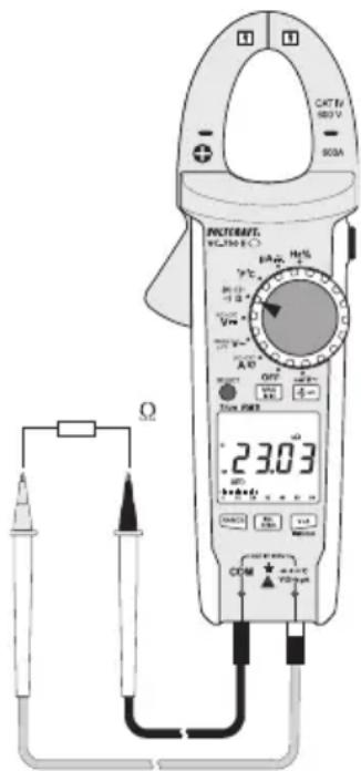
Make sure that all objects to be measured (including circuit components, circuits and component parts) are disconnected and discharged.
- Clean the measuring points if necessary. Make sure that the measuring points you touch with the probe tips are free from dirt, oil, solder lacquer and other similar substances. These substances may distort the measurement.
- Select < > mode. [MΩ] will appear on the display. The main display shows [OL].
- Insert the red test lead into the socket and the black test lead into the COM socket.
- Check the test leads by connecting the two test probes together.
- A resistance value of approx. 0 - 0.5 Ω should be shown (inherent resistance of the test leads). The lead resistance in high-impedance measurements is negligible.
- For low-impedance measurements, press the REL/ZERO button while connecting the two test probes together to discount the inherent impedance of the test leads. The display will be reset to 0. Automatic range selection will be disabled and [4] will appear on the display.
-
The REL/ZERO button only works when a measured value is displayed. It cannot be used when [OL] is displayed.
-
Connect the two test probes to the object that you want to measure.
- The measurement (if not [OL]) will be indicated on the main display (provided that the object you are measuring is not highly resistive or disconnected).
- Wait until the reading stabilises.
- This may take a few seconds for resistances greater than 1 MΩ.
- [OL] (overload) indicates that the measuring range has been exceeded or that the circuit was disconnected.
- After measuring, remove the test leads from the measured object and turn the multimeter off.
text_image
CAT Tr 180V 90A PROMATE VCL350 6°C 23.03 Ω OFF Power Current DCM + - + - + - + - + - + - + - + - + - + - + - + - + - + - + - + - + - + - + - + - + - + - + - + - + - + - + - + - + - + - + - + - + - + - + - + - + - + -20. Measuring – Capacitance

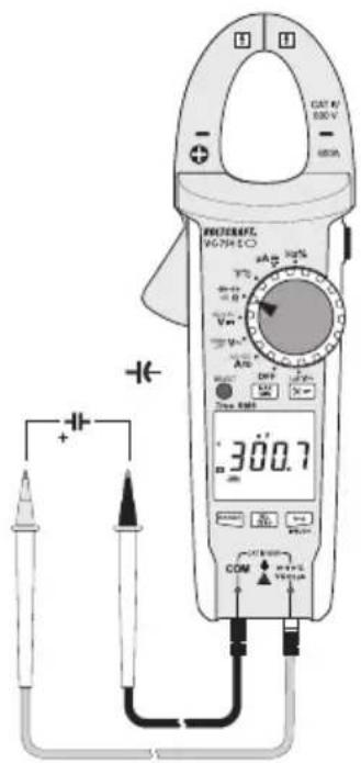
Make sure that all objects to be measured (including circuit components, circuits and component parts) are disconnected and discharged.
Always pay attention to the polarity when using electrolytic capacitors.
- Select < >mode. [n F] will appear on the display.
- Insert the red test lead into the socket and the black test lead into the COM socket.
- Due to the sensitive measuring input, the display may show a reading even with "open" measuring leads. Press the REL/ZERO button to reset the display to 0. Automatic range selection will be disabled and [Δ] will appear on the display.
- This is recommended for small capacitances in the nF range.
- Connect the two test probes (red = positive / black = negative) to the object that you want to measure (capacitor).
- The measured capacitance will be shown on the main display after a few seconds.
- Wait until the reading stabilises.
- This may take a few seconds for capacitances greater than 40 F.
- [OL] (overload) indicates that the measuring range has been exceeded.
- After measuring, remove the measuring leads from the measured object and turn the multimeter off.
text_image
CAT 4V 500 V - 600A ELECTRICAL V-700 V + - 300.7 COM +/-21. Measuring – Temperature

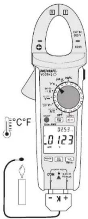
When taking a temperature measurement, only allow the temperature probe to come into contact with the surface of the measured object. The multimeter must not be exposed to temperatures below or in excess of the operating temperature, as this may lead to incorrect measurements.
The temperature probe must only be used on voltage-free surfaces.
a) Introduction
- The supplied temperature probe can measure temperatures from -40 to +250 °C.
- To use the full temperature range (-40 bis +1000 °C), purchase a Type-K thermal sensor. An adapter plug is required to connect Type-K sensors with a miniature connector.
- All K-type thermal sensors can be used for taking temperature measurements. The temperature is displayed in °C or °F.
b) Measuring procedure
- Select < ^ C^ F> mode. [°F °C] will appear on the display.
-
Insert the red test lead into the socket and the black test lead into the COM socket.
-
When using a thermal sensor with miniature connectors, connect the sensor to a compatible adapter.
-
The two contacts on the thermal sensor plug have a different width to ensure that they are connected correctly.
-
The main display indicates the measured temperature in ^ C. The small display indicates the measured temperature in ^ F.
- [OL] indicates that the measurement range was exceeded or the sensor was disconnected.
- After measuring, remove the sensor and turn off the multimeter.
text_image
CAT 1V 800 V - 600A BUTSRAFT. VCT-759 E-O 0253.0 123 - K+22. Testing – Diode

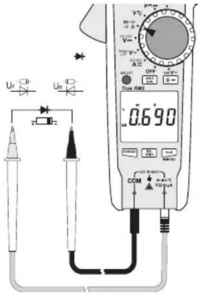
Make sure that all objects to be measured (including circuit components, circuits and component parts) are disconnected and discharged.
- Select < >mode. [ V ] will appear on the display.
- Insert the red test lead into the socket and the black test lead into the COM socket.
- Check the test leads by connecting the two test probes together. A value of approx. 0.000 V should be shown.
- Connect the two test probes to the object that you want to measure (diodes).
- The main display indicates the measured continuity voltage ("UF") in Volts (V).
- [OL] indicates that the diode is reverse-biased or defective. Try taking the measurement again in the opposite polarity.
- After measuring, remove the test leads from the measured object and turn the multimeter off.
text_image
Uf Uin - + - SELECT OFF Ist V~ + - Trans RMS 0.690 u RANGE H1 V1 COM +/- V2 +/-23. Testing – Continuity

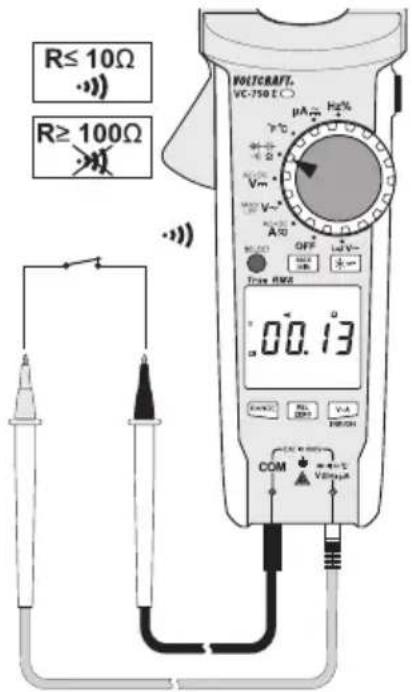
Make sure that all objects to be measured (including circuit components, circuits and component parts) are disconnected and discharged.
- Select < >mode. [ ] will appear on the display.
- Insert the red test lead into the socket and the black test lead into the COM socket.
- If the measured resistance is equal to or less than 10 , the multimeter will beep to indicate continuity.
- The continuity test measures resistances of up to 600 Ohm.
- [OL] (overload) indicates that the measuring range has been exceeded or that the circuit was disconnected.
- After measuring, remove the test leads from the measured object and turn the multimeter off.
text_image
R≤ 10Ω R≥ 100Ω VOLTCRAFT. VC-750 E μA Hz - V - Vm - A - OFF - V~ Time RMS 00.13 COM VDDI V-A REFIN24. Testing – Motor direction (3-phase)
a) Introduction
You can use the multimeter to identify the direction of rotation in a 3-phase power supply. Only two test leads are needed in this mode. The phase conductors (L1, L2 and L3) must be scanned one after another. The multimeter detects the phase shift and indicates the direction of rotation (rotary field) with an arrow.
b) Special notes
- There may be signal interference when measuring 3-phase motors with a variable frequency drive.
• To minimize interference, extend the measuring duration to at least 30 seconds. - The rated voltage may not be entirely accurate for motors with a variable frequency drive and should be used for reference purposes only.
c) Testing procedure
- Select < >mode.
-
Press and hold the SELECT button until [ 🔒 ] flashes on the display. < Motor > mode is enabled.
-
[AC V Hz] will appear on the display.
- Automatic range selection will be disabled and the 600 V range will be selected.
-
Note: If the meter is in
mode you cannot switch to mode. -
A reading of approximately 0.0 V will appear on the display.
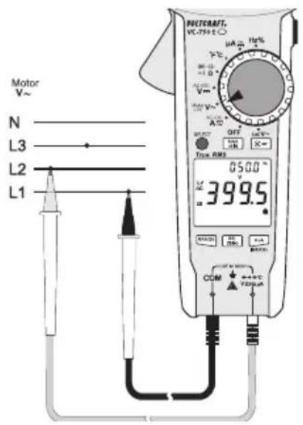
- Insert the red test lead into the socket and the black test lead into the COM socket.
- Connect the black test probe to the L1 phase conductor. This connection should be kept in place for the entire test.
- Connect the red test probe to the L2 phase conductor.
- When two phase conductors are detected:
- The multimeter beeps and [💡] will stop flashing and stays constant.
- The main display indicates the measured voltage.
-
The small display indicates the measured frequency.
-
Connect the red test probe to phase conductor L3 within 5 seconds.
- If the probe is not connected within 5 seconds, the multimeter will stop taking measurements and you will need to start again.
-
The multimeter analyses the phase shift of the three phase conductors and indicates the direction of rotation using two symbols:
-
3=2Clockwise = Right-pointing arrow
- 32 Anticlockwise = Left-pointing arrow
text_image
Motor V~ N L3 L2 L1 POTCRAFT. VC-755 E A OFF Tota RMS 050.0 ° RC 399.5 R COM +0.0°C +0.0mA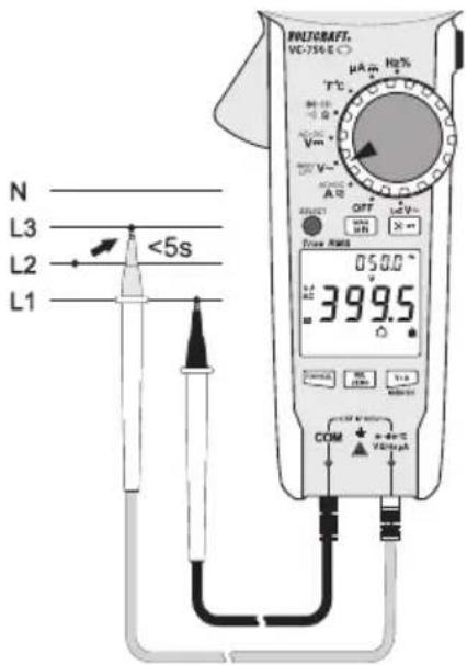
text_image
N L3 L2 L1 <5s COM 399.5 OFF 050.0 V V T°C μA m Hg% V/m V~ A B Power DC DC DC DC DC DC DC DC DC DC DC DC DC DC DC DC DC DC DC DC DC DC DC DC DC DC DC DC DC DC DC DC DC DC DC DC DC DC DC DC DC DC DC DC DC DC DC DC DC DC DLC DC DC DC DC DC DC DC DC DC DC DC DC DC DC DC DC DC DC DC DC DC DC DC DC DC DC DC DC DC DC DC DC DC DC DC DC DC DC DC DC DC DC DC DC DC DC DC DC DC NC- Press the SELECT button to start a new test. Follow the previously described steps.
- To disable this mode, press and hold SELECT for 2 seconds.
- After measuring, remove the test leads from the measured object and turn the multimeter off.
25. Cleaning and maintenance
a) General information

Regularly check the device and test leads for signs of damage.
- The multimeter should be calibrated once a year to ensure that it remains accurate.
- The multimeter is maintenance-free (apart from occasional cleaning and replacing the batteries).
b) Cleaning
Always observe the following safety instructions before cleaning the device:

Opening any covers on the product or removing parts – unless this is possible by hand – may expose voltage-carrying components.
Before cleaning or repairing the device, disconnect all cables from the multimeter and the measured object, and then switch the multimeter off.
- Do not use abrasive detergents, petrol, alcohol or other similar chemicals to clean the device. These may corrode the surface of the multimeter. In addition, the vapours emitted by these substances are explosive and harmful to your health. Do not use sharp-edged tools, screwdrivers or metal brushes to clean the device.
- Use a clean, damp, lint-free and antistatic cloth to clean the device/display and the test leads. Allow the product to dry completely before using it again.
26. Disposal

Electronic devices are recyclable waste materials and must not be disposed of in household waste.
dispose of the product according to the relevant statutory regulations.

ies should be disposed of separately from the product.
Battery disposal

As the end user, you are required by law to return all used batteries. They must not be placed in household waste.
Batteries that contain harmful substances are labelled with this symbol to indicate that they must not be placed in household waste. The abbreviations for heavy metals in batteries are: Cd = Cadmium, Hg = Mercury, Pb = Lead. You can return used batteries to a local recycling point or battery retailer.
You thus fulfil your statutory obligations and contribute to the protection of the environment.
27. Troubleshooting
The multimeter was designed using the latest technology and is safe to use. However, problems and malfunctions may still occur.
This section tells you how to troubleshoot common issues:

Always observe the "Safety instructions" when troubleshooting.
| Fault Possible cause Solution | ||
| The multimeter does not work. Are the batteries empty? Check the battery status and replace the batteries if necessary. | ||
| The measured value does not change. | Have you selected the wrong measuring mode (AC/DC)? | Check the display (AC/DC) and select another mode. |
| Did you use the wrong measuring inputs? | Check that the test leads are connected to the correct inputs.Do you need to use the current clamp? | |
| Is the hold function enabled? Disable the hold function . | ||
| The multimeter cannot take measurements in the μA range. | Has the measuring range been exceeded? | Reduce the current to under 2000 μA. |

Apart from the troubleshooting steps described above, all repair work must be done by an authorised specialist. If you have questions about the multimeter, please contact our technical support team.
28. Technical data
Display....6000 Counts (digits)
Sample rate ....Approx. 3 readings/second
AC measurement method......True RMS, AC-coupled
Test lead length ....Approx. 80 cm
Measuring impedance ≥10M (V-range, LoZ: 300 K )
Measuring socket clearance....19 mm (COM-V)
Current clamp opening 33 mm
Automatic switch-off ....After approx. 15 minutes (can be disabled manually)
Power supply 3 AAA batteries
Current consumption ....Approx. 36 mA (without display backlight)
Operating conditions....+18 to +28 °C (<75 % RH)
Operating height....Max. 2000 m
Storage temperature....-20 to +60 °C (<80 % RH)
Weight ....Approx. 340 g
Dimensions (L x W x H)....235 x 83 x 45 mm
Measurement category.....CAT IV 600 V
Pollution degree....2
Complies with the following safety standards...EN61010-1, EN 61010-031, EN 61010-2-032, EN 61010-2-033
Protection type....IP54 (dust and splash-proof)
Measuring tolerances
Statement of accuracy in ± (% of reading + display error in counts (= number of smallest points)). These accuracy readings are valid for one year at a temperature of +23 °C ( ± 5 °C) and a relative humidity of less than 75 % (non-condensing). If the multimeter is used outside of this temperature range, use the following coefficient to calculate the accuracy. +0.1 x (specified accuracy)/1 °C
The accuracy of measurements may be affected when the multimeter is used in a high-frequency electromagnetic field. In electromagnetic fields of up to 1 V/m, the accuracy values stated below increase by 5 % of the measured value. Electromagnetic fields stronger than 1 V/m can lead to incorrect measurements.

Never exceed the maximum permitted input values. Never touch circuits or circuit components if they may carry voltages greater than 33 V/ACrms or 70 V/DC. This may cause a fatal electric shock!
a) Direct voltage (V/DC)
| Range Resolution Accuracy | ||
| 6.000 V 0.001 V ± (0.6 % + 3) | ||
| 60.00 V 0.01 V | ± (0.9 % + 6) | |
| 600.0 V 0.1 V | ||
| 600 V overload protection; Impedance: 10 MΩSpecified measuring range: 5 – 100 % of the measuring range | ||
b) Alternating voltage (V/AC)
| Range Resolution Accuracy | ||
| 6.000 V 0.001 V | ± (1.0 % + 6)60.00 V 0.01 V | |
| 600.0 V 0.1 V | ||
| 600.0 V "LoZ" 0.1 V ± (2.5 % + 6) | ||
| 600.0 V "Motor" 0.1 V ± (2.0 % + 6) | ||
| Frequency range: 40 Hz – 1 kHz ; 600 V overload protection; Impedance: 10 MΩ (LoZ: 300 kΩ)Specified measuring range: 5 – 100 % of the measuring rangeThe multimeter may display ≤ 5 counts if a measuring input is short-circuited.After using the LoZ feature, leave the multimeter for 1 minute before using it again. | ||
| TrueRMS peak (Crest Factor (CF)) ≤ 3 CF to 600 VTrueRMS peak for non-sinusoidal signals plus toleranceCF >1.0 – 2.0 + 3%CF >2.0 – 2.5 + 5%CF >2.5 – 3.0 + 7% | ||
| Criteria for phase detection in "Motor" mode: >80–600 V/AC, 50–80 Hz | ||
c) AC + DC voltage
| Range Resolution Accuracy | ||
| 6.000 V 0.001 V | ± (2 % + 6) | |
| 60.00 V 0.01 V | ||
| 600.0 V 0.1 V | ||
| Frequency range 40 – 400 Hz; 600 V overload protectionSpecified measuring range: 5–100 % of the measuring rangeTrueRMS peak (Crest Factor (CF)) ≤ 3 CF to 600 VTrueRMS peak for non-sinusoidal signals plus toleranceCF >1.0 – 2.0 + 3%CF >2.0 – 2.5 + 5%CF >2.5 – 3.0 + 7% | ||
d) Direct current ( A/DC)
| Range Resolution Accuracy | ||
| 2000 μA 1 μA ±(0.9 % + 6) | ||
| 600 V overload protectionAutomatic current limitation with integrated PTR components. | ||
e) Alternating current ( A/AC)
| Range Resolution Accuracy | ||
| 2000 μA 1 μA ±(1.5 % + 6) | ||
| Frequency range: 40–400 Hz; 600 V overload protectionAutomatic current limitation with integrated PTR components. | ||
f) Alternating current (A/AC, clamp measurements)
| Range Resolution Accuracy | ||||
| 40 – 100 Hz 100 – 400 Hz | ||||
| A 60.00 A 0.01 A | ±(1.8 % + 8) ±(3.5 % + 6) | |||
| 600.0 A 0.1 A | ||||
| Frequency range 40 – 400 Hz; 600 V overload protectionSpecified measuring range: 5 – 100 % of the measuring rangeThe multimeter may display <2 counts when a measuring input is open | ||||
| TrueRMS peak (Crest Factor (CF)) ≤3 CF to 600 VTrueRMS peak for non-sinusoidal signals plus toleranceCF >1.0 – 2.0 + 3%CF >2.0 – 2.5 + 5%CF >2.5 – 3.0 + 7% | ||||
g) AC + DC current
| Range Resolution Accuracy | |||
| 40 – 100 Hz 100 – 400 Hz | |||
| 60.00 A 0.01 A | ±(3 % + 6) ±(4.5 % + 6) | ||
| 600.0 A 0.1 A | |||
| 600 A overload protection | |||
| True RMS applicable for range 5 – 10 %Frequency range 40 – 400 Hz;TrueRMS peak (Crest Factor (CF)) ≤3 CF to 600 VTrueRMS peak for non-sinusoidal signals plus toleranceCF >1.0 – 2.0 + 3%CF >2.0 – 2.5 + 5%CF >2.5 – 3.0 + 7% | |||
h) Resistance
| Range Resolution Accuracy | ||
| 600.0 Ω* 0.1 Ω ±(1.2 % + 3) | ||
| 6.000 KΩ 0.001 KΩ | ±(1.0 % + 3)60.00 KΩ 0.01 KΩ | |
| 600.0 KΩ 0.1 KΩ | ||
| 6.000 MΩ 0.001 MΩ ±(1.5 % + 3) | ||
| 60.00 MΩ 0.01 MΩ ±(2.5 % + 6) | ||
| 600 V overload protectionMeasuring voltage: Approx. -2.8 V (60/600 Ω-measuring range), -1 V (other ranges)Measuring current: Approx. -1.4 mA*After discounting test lead resistance | ||
i) Acoustic continuity tester
| Measuring range Resolution | |
| 99.99 Ω 0.01 Ω | |
| ≤10 Ω continuous tone; ≥100 Ω no toneOverload protection: 600 VTest voltage Approx. -3.2 VTest current -1.4 mA | |
j) Capacity
| Range Resolution Accuracy | ||
| 60.00 nF 0.01 nF | ± (4 % + 6) | |
| 600.0 nF 0.1 nF | ||
| 6.000 μF 0.001 μF | ||
| 60.00 μF 0.01 μF | ||
| 600.0 μF 0.1 μF | ||
| 6.000 mF 0.001 mF ± 10 % | ||
| 60.00 mF 0.01 mF ± 13 % | ||
| 600 V overload protectionThe accuracy values are valid when REL mode is enabled | ||
k) Diode test
| Test voltage Resolution | |
| approx. 3.0 V/DC 0.001 V | |
| Overload protection: 600 V; Test voltage: 1.8 mA typ. | |
I) Frequency "Hz" (electronic)
| Range Resolution Accuracy | ||
| 10 Hz – 99.99 Hz* 0.01 Hz | ±(0.1 % + 5) | |
| 999.9 Hz 0.1 Hz | ||
| 9.999 kHz 0.001 kHz | ||
| 99.99 kHz 0.01 kHz | ||
| 999.9 kHz 0.1 kHz | ||
| 40.00 MHz 0.01 MHz | ||
| 600 V overload protectionSignal level (without DC component):≤100 kHz: 200 mV – 30 Vrms>100 kHz – <1 MHz: 600 mV – 30 Vrms≥1 MHz – <10 MHz: 1 V – 30 Vrms10 MHz – 40 MHz: 1.8 V – 30 Vrms* The frequency measuring range starts from 10 HzThe standard measuring range includes frequencies ≤10 kHz. | ||
m) Frequency "Hz" (electrical)
| Range Resolution Accuracy | ||
| 40 – 400 Hz 0.1 Hz Not specified | ||
| Signal level: Sensitivity ≥30 VrmsA/AC 40 – 400 Hz Resolution: 0.1 HzV/AC 40 – 1 kHz Resolution: 0.1 Hz – 1 HzSpecified measuring range: 5 – 100 % of the measuring range | ||
n) Temperature
| Range Resolution Accuracy* | ||
| -40 to 0 °C 1 °C ± 5 °C | ||
| >0 to +600 °C 1 °C ±(2 % + 5 °C) | ||
| >+600 to +1000 °C 1 °C ±(2.5 % + 5 °C) | ||
| -40 to +32 °F 1 °F ± 9 °F | ||
| >+32 to +1112 °F 1 °F ±(2 % + 9 °F) | ||
| >1112 to +1832 °F | 1 °F ±(2.5 % + 9 °F) | |
| *Without sensor toleranceSensor type: Type K thermal elementOverload protection: 600 V | ||
Page
France (email): technique@conrad-france.fr
Suisse:
www.conrad.ch
www.biz-conrad.ch
DC Courant continu DC
natural_image
Diagram of a handheld device with two labeled pins (AAA) on its side panel, no text or symbols present.c) Tension alternative (V/AC)
text_image
L N LoZ V~ 230.0 1-2 OFF Diam AM2 V Y Vcc Vcc Vcc Vcc Vcc Vcc Vcc Vcc Vcc Vcc Vcc Vcc Vcc Vcc Vcc Vcc Vcc Vcc Vcc Vcc Vcc Vcc Vcc Vcc Vcc Vcc Vcc Vcc Vcc Vcc Vcc Vcc Vcc VccAnnulation et addition
text_image
N ~ L RACUMBER VOLTAGE 100A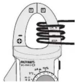
text_image
PHOCRAFT HC-1933.0 + - 2A + 10V T°C 400 V 500 V 800 V 100 V 120 V 140 V 160 V 180 V 200 V 220 V 240 V 260 V 280 V 300 V 320 V 340 V 360 V 380 V 400 Vd) Courant continu (A)
line
| Time Segment | Value | | ------------ | ----- | | Start | 0 A | | Stop | 0 A |text_image
Hertz% G 50.00 50.88 COM VOLTS 8 RCA DC DC DC DC DC DC DC DC DC DC DC DC DC DC DC DC DC DC DC DC DC DC DC DC DC DC DC DC DC DC DC DC DC DC DC DC DC DC DC DC DC DC DC DC DC DC DC DC DC DC DSCA VOLTS 8 RCA DC DC DC DC DC DC DC DC DC DC DC DC DC DC DC DC DC DC DC DC DC DC DC DC DC DC DC DC DC DC DC DC DC DC DCtext_image
Diagram of a multimeter setup with labeled components including U_F, U_R, CM, and digital display showing voltage reading.Dimensions (L x l x P)....235 x 83 x 45 mm
natural_image
Technical line drawing of a handheld device casing with two labeled pins (no text or symbols present)text_image
MUSAMTS NO 758-10 V=- V~ 050.0 230.0 (±0.0)Ω COM ±0.0 ±0.0 ±0.0 ±0.0 ±0.0 ±0.0 ±0.0 ±0.0 ±0.0 ±0.0 ±0.0 ±0.0 ±0.0 ±0.0 ±0.0 ±0.0 ±0.0 ±0.0 ±0.0 ±0.0 ±0.1 ±0.1 ±0.1 ±0.1 ±0.1 ±0.1 ±0.1 ±0.1 ±0.1 ±0.1 ±0.1 ±0.1 ±0.1 ±0.1 ±0.1 ±0.1 ±0.1 ±0.1 ±0.1 ±0.1 ±0.2 ±0.2 ±0.2 ±0.2 ±0.2 ±0.2 ±0.2 ±0.2 ±0.2 ±0.2 ±0.2 ±0.2 ±0.2 ±0.2 ±0.2 ±0.2 ±0.2 ±0.2 ±0.2 ±0.2 ±0.3 ±0.3 ±0.3 ±0.3 ±0.3 ±0.3 ±0.3 ±0.3 ±0.3 ±0.3 ±0.3 ±0.3 ±0.3 ±0.3 ±0.3 ±0.3 ±0.3 ±0.3 ±0.4 ±0.4 ±0.4 ±0.4 ±0.4 ±0.4 ±0.4 ±0.4 ±0.4 ±0.4 ±0.4 ±0.4 ±0.4 ±0.4 ±0.4 ±0.4 ±0.4 ±0.4 ±0.4 ±0.4 ±0.5text_image
N ~ L Vcc Vcc