ETC200 - Temperature Controller VOLTCRAFT - Free user manual and instructions
Find the device manual for free ETC200 VOLTCRAFT in PDF.
| Product Type | Temperature Controller |
| Brand | Voltcraft |
| Model | ETC200 |
| Front Panel Dimensions | 75 x 34.5 mm |
| Cutout Dimensions | 71 x 30 mm |
| Power Supply | 200-240 V/AC, 50-60 Hz, < 3 W |
| Protection Class | II |
| Sensor Protection Rating | IP68 |
| Front Panel Protection Rating | IP54 |
| Sensor Type | NTC, 10 kΩ at +25 °C |
| Measured Temperature Range | -40 °C to +120 °C |
| Accuracy | ±1 °C (from -40 to +70 °C), otherwise ±2 °C |
| Resolution | 0.1 °C (<100 °C), 1 °C (≥100 °C) |
| Relay Load Capacity | 10 A / 240 V/AC max. |
| Operating Modes | Cooling and heating (ETC-200+) |
| Adjustable Functions | Temperature limits, calibration, delay, defrost cycle and duration, alarm, password |
| Operating Temperature | 0 °C to +60 °C |
| Operating Humidity | 20-85% RH, non-condensing |
| Maintenance | Clean with a soft dry cloth; vacuum for dust |
| Safety | Installation by a qualified electrician; do not use in explosive atmosphere |
| Package Contents | Controller, external sensor, user manual |
Frequently Asked Questions - ETC200 VOLTCRAFT
User questions about ETC200 VOLTCRAFT
0 question about this device. Answer the ones you know or ask your own.
Ask a new question about this device
Download the instructions for your Temperature Controller in PDF format for free! Find your manual ETC200 - VOLTCRAFT and take your electronic device back in hand. On this page are published all the documents necessary for the use of your device. ETC200 by VOLTCRAFT.
USER MANUAL ETC200 VOLTCRAFT
Messrate: ....<= 2 Sekunden
Depending on the version, the thermostat can be used with a cooling function ("ETC-100+") or with a cooling or heating function ("ETC-200+").
Read the operating instructions carefully before operating the device; observe all the safety and installation instructions, as well as all other information in this manual!
Any use other than the one described above could damage this product and involves the risk of short circuits, fire, electric shock, etc.
This product complies with the applicable National and European regulations.
All names of companies and products are the trademarks of the respective owner. All rights reserved.
PACKAGE CONTENTS
• Temperature controller
- Temperature sensor
- Operating Instructions
SAFETY INSTRUCTIONS
Please read all the instructions before using this device, they include important information on its correct operation. The warranty will be void in the event of damage caused by failure to observe these safety instructions! We do not assume any liability for any consequential damage!
Nor do we assume any liability for material and personal damage caused by improper use or non-compliance with the safety instructions! In such cases, the warranty will be null and void.
General
- The unauthorised conversion and/or modification of the product is not permitted for safety and approval reasons (CE). Never dismantle the product.
- The product may be operated only on a mains voltage of 200 - 240 V/AC, 50 - 60 Hz. The design of the product complies with the safety class II.
- The product must not be exposed to extreme temperatures, strong vibrations or heavy mechanical stress.
The sensor complies with IP68, the front plate of the temperature controller complies with IP54. Insert a suitable gasket between the front plate and the housing into which the thermostat is to be installed.
- The product is not a toy. It is not suitable for children. The product must only be mounted and operated at a place out of the reach of children.
- In commercial institutions, the accident prevention regulations of the Employer's Liability Insurance Association for Electrical Systems and Operating Materials are to be observed.
- In schools, educational centres, hobby and self-help workshops the operation of the product is to be supervised by trained employees.
- Do not leave packaging material lying around carelessly. It may become a dangerous plaything for children.
- Handle the product with care, it can be damaged by impacts, blows, or accidental drops, even from a low height.
If you see any damage, do not use the product anymore but take it to a specialised workshop or dispose of it in an environmentally friendly manner.
Installation
- The product may only be installed by a qualified technician (e.g. electrician) who is familiar with the relevant regulations (e.g. VDE, German electrical wiring regulations)!
Improper work, carried out on the mains voltage, endangers not only your own life but also the life of others!
If you do not have the expertise required for the installation, do not install it yourself but ask a qualified technician.

- The product is not suitable for installation and operation in areas where there is a risk of explosion.

hermostat may be mounted and operated only when installed permanently in an enclosed casing.
- Only suitable power cables must be used for connection of the thermostat to the mains voltage.
If in doubt about how to connect the device correctly, or should any questions arise that are not answered in these operating instructions, please contact our technical advisory service or another specialist.
Voltcraft®, Lindenweg 15, D-92242 Hirschau, Tel. number 0180/586 582 7
INSTALLATION AND CONNECTION
- Choose a suitable installation site for the thermostat. The required casing section is approx. 71 × 30mm .
- The temperature controller can be easily fastened in the casing section by two moveable holding clamps.
- The connecting clamps can be found under a cover plate (fastened to the casing of the thermostat by a screw) at the backside.
→ The polarity is not important for the connection of the external sensor.

Do not place the sensor cable next to mains cables! Keep the sensor cable away from sharp edges or rotating/moving parts!
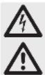
Thermostat "ETC-100+":
A = Screw terminals 7 and 9: Connection of the mains voltage
B = Screw terminals 11 and 12: Connection for external sensor
C = Screw terminals 1 and 3: Switching output
text_image
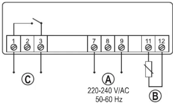
1 2 3 7 8 9 11 12 ① C A 220-240 V/AC 50-60 Hz BThermostat "ETC-200+":
A = Screw terminals 7 and 9: Connection of the mains voltage
B = Screw terminals 11 and 12: Connection for external sensor
C = Screw terminals 1 and 3: Switching output
D = Screw terminals 5 and 6: Switching output for defrost function
text_image
1 2 3 4 5 6 7 8 9 11 12 ① ② ③ ④ ⑤ ⑥ ⑦ ⑧ ⑨ ③ C D A ④ ⑤ ⑥ ⑦ ⑧ ⑨ 220-240 V/AC 50-60 Hz BLED SIGNALS

LED lit Normal function
LED fl ashes Switch-on delay active

LED lit Nomal defrost function (only "ETC-200+")
LED fl ashes fast Manual defrost function (only "ETC-200+")
LED fl ashes slowly Setup menu active
OPERATING FUNCTIONS
After switching on the mains power supply, the display briefly shows all display segments and then switches to the currently measured temperature (e.g. 21.5 °C).
Displaying limit values
- Press key "▲" briefly: The upper limit value is displayed
- Press key "▼" briefly: The lower limit value is displayed
→ After about 2 seconds, the display switches back to the current temperature again.
Opening the setup menu
A three-digit password has to be entered to prevent alteration of the settings by unauthorised persons. The password "111" is pre-set by the manufacturer upon delivery.
To open the setup menu, proceed as follows:
- Keep the "SET" button pressed for 3 seconds; 3 dashes appear on the display, the left one of which fl ashes.
- Set the first digit of the password with the buttons "▲" and "▼".
- Confirm with the "❄" button; the second dash starts flashing.
- Set the second digit of the password with the buttons "▲" and "▼".
- Confirm with the "❄" button; the third dash starts flashing.
- Set the third digit of the password with the buttons “▲” and “▼”.
- Confirm your input with the button ✿".
- If the password ("111" in the factory setting) was entered correctly, the display shows "F01" and you can select the desired function with the buttons "▲" and "▼".
If an incorrect password was entered, three dashes appear again and the password has to be re-entered.
→ If the password is entered three times incorrectly, or if for about 30 seconds no button is pressed, the display switches back to the actual temperature.
Selecting functions in the setup menu
- Select the functions "F01"... "F08" and "P01"... "P03" with the buttons "▲" and "▼".
→ The functions F05, F06, F07 and F08 are not available for "ETC-100+".
| Code Function Setup range Factory setting | |||
| F01 Upper temperature limit -39....+120 °C -15 °C | |||
| F02 Lower temperature limit -40....+119 °C -18 °C | |||
| F03 Temperature calibration -5....+5 °C | 0 °C | ||
| F04 Switch-on delay | 0....30 min | 3 min | |
| F05 Defrost cycle | 0....99 h | 6 h | |
| F06 Defrosting duration | 0....99 min | 30 min | |
| F07 Temperature alarm limit 0....20 °C | 20 °C | ||
| F08 0 = cooling mode, 1 = heating mode | 0, 1 | 0 | |
| P01 First digit of password | 0....9 | 1 | |
| P02 Second digit of password | 0....9 | 1 | |
| P03 Third digit of password | 0....9 | 1 | |
Displaying and changing the setting value
- With the button ❄* the current setting value of the respective function is shown.
- When the setting value appears on the display, it can be adjusted with the buttons “▲” and “▼”. For a quick adjustment, press and hold the corresponding button for a longer period of time.
- Press the "SET" button briefly; the setting value flashes for 2 seconds and the display returns to the function selection.
→ The new value is not saved yet, but only added to the temporary memory.
Saving all setting values
Keep the "SET" button pressed for 3 seconds; all setting values are thus added and saved. The setup menu closes automatically and the current temperature appears again in the display.
Not saving setting values
If you do not press any button within 30 seconds, the thermostat returns to the current temperature. Possible adjustments are not saved; the previous setting values remain activated.
→ For this reason, do not allow too much time in the changing of setting values; otherwise the setting mode will close without saving!
COOLING MODE
The cooling process is started if the measured temperature is above the upper temperature limit (adjustable with function "F01").
The cooling process is stopped if the measured temperature drops below the lower temperature limit (adjustable with function "F02").
HEATING MODE ("ETC-200+")
→ This function is available only for "ETC-200".
In the heating mode, the heating process is started if the measured temperature drops below the lower temperature limit (adjustable with the function "F02").
The heating process is stopped if the measured temperature is above the upper temperature limit (adjustable with function "F01").
SWITCH-ON DELAY
→ This function is active only during the cooling mode.
When the power supply is switched on, the thermostat measures the current temperature.
If this temperature is above the upper temperature limit (function "F01"), the cooling process is not yet started; instead, the thermostat waits for the time of the switch-on delay (function "F04"; the value can be set to 0-30 minutes; the factory setting is 3 minutes).
This protects the compressor from starting too often in case of an error (e.g. disturbances in the power supply).
DEFROST FUNCTION ("ETC-200+")
→ This function is available only for "ETC-200+"; furthermore, the cooling mode must be activated (function "F08" must be set to "0").
The automatic defrosting process is started according to the settings of the defrost cycle (function "F05"); the duration is determined in function "F06".
The defrost function is deactivated if either defrost cycle (function "F05") or defrosting duration (function "F06") are set to "0".
Start a manual defrost process by pressing and holding the button "or at least 3 seconds until the defrost LED " flashes. Stop the manual defrosting procedure in the same manner (press the button "approx. 3 seconds until the defrost LED goes out).
ALARM FUNCTIONS
- Input error
If "Er" flashes on the display, an error was determined during saving. This can occur during the initial startup or during the saving of setting values. Press any key.
- Sensor alarm
If "E01" flashes on the display and an alarm sounds simultaneously, the thermostat detected an error in the sensor (e.g. faulty connection or no cable connected, cable too long)
• Temperature range alarm
If the measured temperature exceeds the permissible temperature range (-40....+120 °C), "E02" fl ashes in the display and an alarm sounds.
- Alarm when exceeding the temperature alarm limit ("ETC-200+")
A value between 0....20 °C can be set as temperature alarm limit in function "F07" ("ETC-200+" only).
The alarm is triggered (display fl ashes and alarm sounds) if:
measured temperature > (upper temperature limit) + (temperature alarm limit)
Example: 123 °C > (80 °C) + (20 °C) → alarm is triggered
or
measured temperature < (lower temperature limit) - (temperature alarm limit)
Example: -40 °C < (-10 °C) - (20 °C) → alarm is triggered
- Deactivating the alarm sound
Press any key to turn the alarm sound off.
TEMPERATURE CALIBRATION
The temperature can be calibrated with the function "F03" in the setup menu by setting a correction value (-5 °C.....+5 °C).
CHANGING THE PASSWORD
- Select the setup menu (see "OPERATING FUNCTIONS" and then "Opening the setup menu"). Enter the current password (factory setting: "111").
- If „F01“ appears on the display, select the function “P01” with the buttons “▲” and “▼”, and press the button “💡”.
- Set the first digit of the password with the buttons “▲” and “▼” and briefly press the “SET” button. The display flashes briefly if the value was changed.
- Select the function „P02“ with the buttons “▲” and “▼”, and press the button “✿”.
- Set the second digit of the password with the buttons "▲" and "▼" and briefly press the "SET" button. The display flashes briefly if the value was changed.
- Select the function „P03“ with the buttons “▲” and “▼”, and press the button “✿”.
- Set the third digit of the password with the buttons "▲" and "▼" and briefly press the "SET" button. The display flashes briefly if the value was changed.
- Keep the "SET" button pressed until the current temperature is displayed again (approx. 3 seconds).
The new password is now saved.
RESETTING PASSWORD TO FACTORY SETTING
If you forgot your password, you can reset it to "111". Proceed as follows:
- Separate the thermostat from the mains voltage.
- Keep both buttons "SET" and "SET" pressed at the same time, and switch on the mains voltage. "ON" will appear on the display.
- Release both buttons. The current temperature is shown in the display, the password is reset to "111".
CLEANING
Dust can be very easily removed using a soft, clean, long-bristled brush and a vacuum cleaner.
If you want to wipe the display, use a clean soft dry cloth. Do not use aggressive detergents, or there could be changes in colour. Do not press the display too firmly. This may lead to scratch marks and/or damage the display.
HANDLING

- Observe all safety and mounting instructions contained in these operating instructions.

ot expose the product to the following unfavourable ambient conditions at the site of installation:
- Damp or excess air humidity
- Extreme cold (<-5°C) or heat (>+55°C), direct sunlight
-
Dust
or
fl ammable gases, fumes or solvents
- Strong vibrations, impacts or blows,
- Strong magnetic fields such as those found close to machinery or loudspeakers
- Only operate the temperature controller when it is firmly assembled in an enclosed casing.
- When assembling and operating the device, make sure the cable to the sensor is not bent or jammed.
DISPOSAL

Please dispose of the device, when it is no longer of use, according to the current statutory requirements.
TECHNICAL DATA
Operating voltage: 200 - 240 V/AC, 50-60 Hz
Input: <3 W
Protection class: ....II
Sensor safety class: IP68
Front plate safety class: IP54
Assembly dimensions (W x H): 71 x 30 mm
Dimensions of frontplate: 75 x 34.5 mm
Operating temperature: 0 °C to +60 C°
Humidity during operation: 20 - 85% rel. humidity, not condensing
Accuracy: ± 1^ (at -40^ to +70^ ), otherwise ± 2^
Temperature range of sensor: -40 °C to +120 °C
Sensor type: NTC, 10 kΩ at +25 °C
Resolution: 0.1 °C (< 100°C)
1^ (>= 100^)
Measuring rate: ....<= 2 seconds
Relay loading capacity: ....max. 10 A/240 V/AC

NOTICE D'EMPLOI
CE
VERSION02/12
RÉGULATEUR DE TEMPÉRATURE
N° DE COMMANDE 19 69 79 (TYPE «ETC-100+»)
N° DE COMMANDE 19 69 94 (TYPE «ETC-200+»)
UTILISATION CONFORME
© Copyright 2012 by Voltcraft

GEBRUIKSAANWIJZING
CE
VERSIE02/12
TEMPERATUURREGELAAR
BESTELNR. 19 69 79 (TYPE „ETC-100+“)
BESTELNR. 19 69 94 (TYPE „ETC-200+“)
BEOOGD GEBRUIK
© Copyright 2012 by Voltcraft V1_0212_01/HD