LSG3 - Cable detector VOLTCRAFT - Free user manual and instructions
Find the device manual for free LSG3 VOLTCRAFT in PDF.
| Product type | Cable detector (cable tester) with transmitter (Net-Toner) and receiver (Net-Probe) |
| Brand | Voltcraft |
| Model | LSG-3 |
| Dimensions (Net-Toner) | 125 x 68 x 26 mm |
| Dimensions (Net-Probe) | 210 x 40 x 28 mm |
| Weight (Net-Toner, without battery) | 120 g |
| Weight (Net-Probe, without battery) | 90 g |
| Power supply | 2 x 9 V block batteries (not included) |
| Main functions | Continuity test, polarity test on telephone lines, cable tracing / identification, analog telephone line test, test signal generation (Hi/Lo frequencies), coaxial cable test, RJ11/RJ45/BNC wiring test |
| Supported connectors | RJ11, RJ45, BNC (via adapter), test terminals, alligator clips |
| Maximum voltage protection | 48 VDC / 24 VAC |
| Signal frequencies | Hi: 500-781 Hz, Lo: 446-657 Hz |
| Signal volume | 30 dB |
| Voltage for voice link | 9 V at 600 ohms |
| Consumption (Net-Toner) | Max. 17 mA |
| Consumption (Net-Probe) | Max. 50 mA |
| Ambient temperature | 0 °C to 40 °C |
| Maintenance and cleaning | Clean the exterior with a clean, lint-free cloth, without abrasive detergents or solvents |
| Safety | Do not exceed 48 VDC / 24 VAC; do not use in wet, dusty, or flammable gas environments; ensure cables are de-energized before each test |
| Spare parts and repairability | Replaceable test probe tip (supplied); replaceable 9 V batteries |
| Package contents | Net-Probe, Net-Toner, protective pouch, RJ45 to F adapter, user manual, spare test tip |
Frequently Asked Questions - LSG3 VOLTCRAFT
User questions about LSG3 VOLTCRAFT
0 question about this device. Answer the ones you know or ask your own.
Ask a new question about this device
Download the instructions for your Cable detector in PDF format for free! Find your manual LSG3 - VOLTCRAFT and take your electronic device back in hand. On this page are published all the documents necessary for the use of your device. LSG3 by VOLTCRAFT.
USER MANUAL LSG3 VOLTCRAFT
© Copyright 2008 by Voltcraft®
GB Impressum /legal notice in our operating instructions
These operating instructions are a publication by Voltcraft®, Lindenweg 15, D-92242 Hirschau/Germany, Phone +49 180/586 582 7 (www.voltcraft.de).
All rights including translation reserved. Reproduction by any method, e.g. photocopy, microfilming, or the capture in electronic data processing systems require the prior written approval by the editor. Reprinting, also in part, is prohibited.
These operating instructions represent the technical status at the time of printing. Changes in technology and equipment reserved.
© Copyright 2008 by Voltcraft®
© Copyright 2008 by Voltcraft®
01_1108_02/HK
GB These Operating Instructions accompany this product. They contain important information on setting up and using your Voltage Detector. You should refer to these instructions, even if you are buying this product for someone else.
Please retain these Operating Instructions for future use!
A list of the contents can be found in the Table of contents, with the corresponding page number, on page 23.
Net-Toner (16)....11
text_image
Electrical circuit diagram with labeled components including a meter, switches, and display unitstext_image
Diagram showing connections between a handheld device, multiple earphones, and a handheld device with wireless signals.Net-Probe (1)
natural_image
Diagram of a mobile phone connected to a device via a cable, showing ports and wiring (no text or symbols)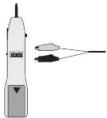
natural_image
Illustration of a handheld electric shaver with two connected wires (no text or symbols)In purchasing this Voltcraft® product, you have made a very good decision for which we should like to thank you.
You have acquired an above-average quality product from a brand family which has distinguished itself in the field of measuring, charging and network technology through particular competence and constant innovation.
With Voltcraft®, you will be equal to difficult tasks as an ambitious hobbyist just as much as a professional user. Voltcraft® offers you reliable technology at an extraordinarily favourable cost-performance ratio.
We are certain: your start with Voltcraft will at the same time be the commencement of a long and profitable co-operation.
We wish you much enjoyment with your new Voltcraft® product!
Table of Contents
Introduction 22
Table of Contents ......23
Intended Use ....23
Scope of delivery....26
Operating elements (see fold-out page) 27
Starting operation 28
Inserting/replacing batteries 28
Net toner (16) 29
Voltage source for voice connection .....29
Continuity test, general ....30
Continuity test on co-axial cables ....31
Polarity test on telephone cables ....31
Checking the telephone cable ....32
Transmitting a test signal to the cable tracing....33
Net probe (1) 34
Cable tracing ....34
Cable test for analogue telephone cables ....35
Disposal of flat batteries / accumulators....37
Servicing and cleaning....38
Disposal 38
Technical data ....39
Intended Use
The cable detector LSG-3 can be used for testing cable continuity, cable occupancy and the routes of cable in telecommunication systems (RJ11/RJ45), data current systems (thin Ethernet (BNC), 10/100Base-T, USOC, TIA 568 A/B, token ring, ATM/TP-PMD) and co-axial cable systems (F plug-in systems) and systems with simple cables.
This product is intended for operation with a 9-V compound battery. The maximum working voltage of 48V direct voltage and 24 V alternating voltage may not be exceeded.
Contact with moisture must be avoided at all times.
Operation is not permitted under adverse ambient conditions. The following are adverse ambient conditions:
- wetness or excessive humidity
- dust and combustible gases, vapours or solvents
- Storms or stormy conditions such as strong electrostatic fields, etc.
Use other than that described above will damage the product and may involve other risks, such as short circuit, fire and electric shock etc. Do not change or modify any part of the product. The safety instructions must be observed at all times!
Safety instructions and danger warnings

The warranty will lapse in case of damage caused by failure to comply with these operating instructions! We do not accept liability for damage to property or injury to persons caused by mishandling or non-compliance with the safety instructions.
This device left the factory in perfect condition in terms of safety engineering.
To maintain this status and ensure safe operation, the user must observe the safety instructions and warnings ("Caution!" and "Note!") contained in these instructions for use. The following symbols and notices must be observed:

Note! Read the instructions for use.

This product has been CE-tested and meets the necessary guidelines.

This symbol indicates useful information for the user..
Measuring instruments and accessories should be kept out of the reach of children!
In commercial institutions, the accident prevention regulations of the Employer's Liability Insurance Association for Electrical Systems and Operating Materials are to be observed..
In schools, training centres, computer and self-help workshops, handling of measuring devices must be supervised by trained personnel in a responsible manner.
For safety and licensing (CE) reasons, unauthorised conversion and/or modifications to the product are not permitted.
Do not expose the device to high temperatures, dampness or strong vibration or excessive mechanical loads.

Cables may only be tested with the cable detector up to 48V DC or 24V AC. Make sure of the voltage limits before every measurement (danger to life).
Product description
The cable detector has been developed especially for a quick check on the spot. Cable continuity, cable occupancy and the course of cables can be tested. As the device has a remote unit, the cables / cable systems to be checked can be tested both before and after installation.
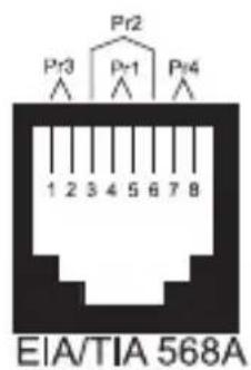
Pin occupancy of individual systems:
text_image
Pr2 Pr3 Pr1 Pr4 1 2 3 4 5 6 7 8 EIA/TIA 568A
text_image
Pr3 Pr2 Pr1 Pr4 1 2 3 4 5 6 7 8 EIA/TIA 568B AT&T 258A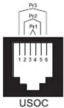
text_image
Pr3 Pr2 Pr1 1 2 3 4 5 6 USOC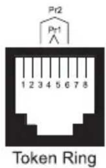
text_image
Pr2 Pr1 1 2 3 4 5 6 7 8 Token Ring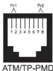
text_image
Pr1 1 2 3 4 5 5 7 8 Pr2 ATM/TP-PMD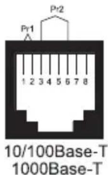
text_image
Pr1 1 2 3 4 5 6 7 8 10/100Base-T 1000Base-TScope of delivery
Net probe (detector)
Net toner (signal transmitter unit)
Storage pouch
Adapter plug (RJ45 plug ± F screw jack)
Operating instructions
Replacement tip for receiver
Operating elements (fold-out page)
1 Net probe (detector)
2 Testing tip
3 Switch-over for loudspeaker/earphone operation
4 RJ45 test jack
5 Earphone jack 2.5 mm mono
6 Test connections for alligator terminal (Test contacts of the RJ45 jack)
7 battery compartment!
8 Loudspeakers
9 Check button
10 Volume control for signal reproduction
11 Optical signal display
12 Test lamp diodes (LED) for polarity test
13 LED display for battery undervoltage
14 Switch-over for telephone test/signal tracing
15 Test adapter RJ45/F jack
16 Net toner (signal transmitter unit)
17 LED display for battery undervoltage
18 Pushbutton for tone frequency (hi / lo)
19 Battery compartment at rear
20 Pushbutton for voltage supply to speech function
21 Test display (line 2, line 1/passage)
22 Switch-over for test mode
23 RJ45 test jack
24 Test terminals (red and black)
25 Test plug (RJ11 for modular telephone jacks)
Starting operation

Before starting up operation, both the intended purpose of use and the safety instructions and technical data are to be observed!
Make sure before starting up operation that the device is suitable for the purpose of use for which it is to be used.
Inserting/replacing batteries
A 9-V compound battery is required for operation (not included in the scope of delivery).
Open the battery compartments (7 and 19) on the back of the two devices, connect the battery clip paying attention to the polarity of the battery and close the compartment again with care.
Replace the battery if, after some period of operation, the undervoltage LEDs (LOW BATT 13/17) appear. To do this, proceed as follows: disconnect the corresponding devices from all connected cables. open the battery compartment (7/9).
remove the flat batteries and insert an unused battery of the same type paying attention to the polarity.

Use only alkaline 9-V compound batteries. These are more efficient and afford a longer operating period than the conventional zinc-carbon batteries.
Close the battery compartment lid after inserting the battery correctly.

Incorrect polarity of the battery will lead inevitably to destruction of the device!
Net toner (16)
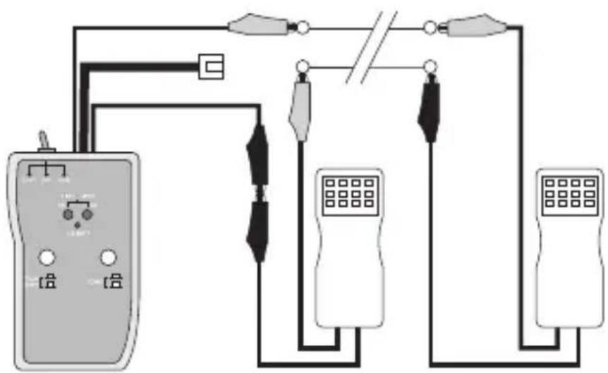
Voltage source for voice connection
The net toner can be used as the source of voltage for voice connections for test purposes.

Make sure before connection that the cables are not alive (danger to life).
- Turn the switch-over for test mode (22) to the central position "OFF".
- Make the connection as depicted using the two crocodile terminals (24) and the test telephone.
- Operate the pushbutton (20) until it snaps in.
- Turn the switch (22) to the left to the position "CONT/Talk".
- The two test telephones are now supplied with voltage.
- Turn the switch-over (22) after the end of the test to the central position "OFF".
text_image
Electrical circuit diagram with labeled components including a meter, switches, and display unitsContinuity test, general
The net toner can be used as an optical continuity tester.

Make sure before connection that the cables are not alive (danger to life).
- Turn the switch-over for test mode (22) to the central position "OFF".
- Connect the two test terminals (24) using the cable to be tested.
- Turn the switch-over (22) to the left to the position "CONT/Talk". The pushbutton (20) may not be pressed.
- The green LED display (21, line2/continuity) displays the continuity status:
brightly lit = little cable resistance medium-lit = high cable resistance not lit = interrupted current circuit
- Turn the switch-over (22) after the end of the test to the central position "OFF" again.

If the ends of the cables to be tested lie too far apart, use a second reference lead for a return path. Wire these two cables together at the end furthest away.
Continuity test on co-axial cables
Co-axial cables can be tested for function/damage in the same manner, .

Make sure before connection that the cables are not live (danger to life).
- Turn the switch-over for testing mode (22) to the central position "OFF".
- Connect the two test terminals (24) using the cable to be tested.
- Switch the switch-over (22) to the left in the position "CONT/Talk". The pushbutton (20) may not be pressed.
- The green LED display (21, line2/continuity) displays the continuity status:
- Time-phased coaxial cable Connect the red test cable (24) to the inside line and the black cable to the outside line/shielding. The display (21) must light up.
- Open co-axial cables. Make the test connection as for time-phased cables. The display (21) may not light up.
- Turn the switch-over (22) after the end of the test to the central position "OFF" again.
Polarity test on telephone cables
Telephone lines can be tested for correct polarity using the net toner. The net toner can test two connection standards; line 1 = contacts 4/5 or line2 = contacts 3/6

Make sure before connection that the voltage on the cables is not greater than 48C DC or 24V AC (danger to life).
- Turn the switch-over for testing mode (22) to the central position "OFF".
- Connect an optional test cable with modular plug (RJ11/RJ45) to the telephone socket and the test jack (24) or
- make the test connection to the two test terminals (23), the red test terminal to the minus contact and the black test terminal to the plus contact.
- the display takes place on the corresponding line LED (21) which is applicable for your standard in three different colours: green = normal, rot = polarity reversed, yellow = alternating voltage.
Checking the telephone cable
Telephone lines can be tested for function using the net toner. For this, you require a second Telephone connection (e.g. a GSM mobile telephone).

Make sure before connection that the voltage on the cables is not greater than 48C DC or 24V AC (danger to life).
- Turn the switch-over for testing mode (22) to the central position "OFF".
- Connect an optional test cable with modular plug (RJ11/RJ45) to the telephone socket to be tested and the test jack (23) or
- make the test connection to the two test terminals (24). the red test terminal to the minus contact and the black test terminal to the plus contact.
- Dial the number of the connection to be tested on the second telephone connection.
- "Ringing" is displayed by the red/green flashing of line 1 LED (21) if installation is correct.
- If you turn the switch-over for testing mode (22) to the left position "CONT", ringing is interrupted.
- Turn the switch-over (22) after the end of the test to the central position "OFF" again.
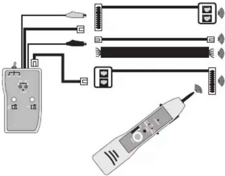
Transmitting a test signal to the cable tracing
The net toner represents in connection with the net probe an efficient cable tracing and lead identification system. The net toner works as a signal transmitter and the net probe as a signal receiver.

Make sure before connection that the cables are not live (danger to life).
- Turn the switch-over for testing mode (22) to the central position "OFF".
- The signal is emitted during testing on all connections and jacks (23/24/25). Make the corresponding connection.

To strengthen the test signal on the cables, connect the black crocodile terminal to the earth of the cable to be tested.
- the test adapter (15) can be used to test the co-axial systems (F-plug norm). - Insert this into the test jack (23).
- Turn the switch-over (22) to the right in the position "TONE".
- The signal frequency can be switched over using the pushbutton (18) (Hi/Lo).
- The display LEDs (21) light up weakly orange.
- For identification, follow the instruction in the next section of the net probe
- Turn the switch-over (22) after the end of the test to the central position "OFF" again.
text_image
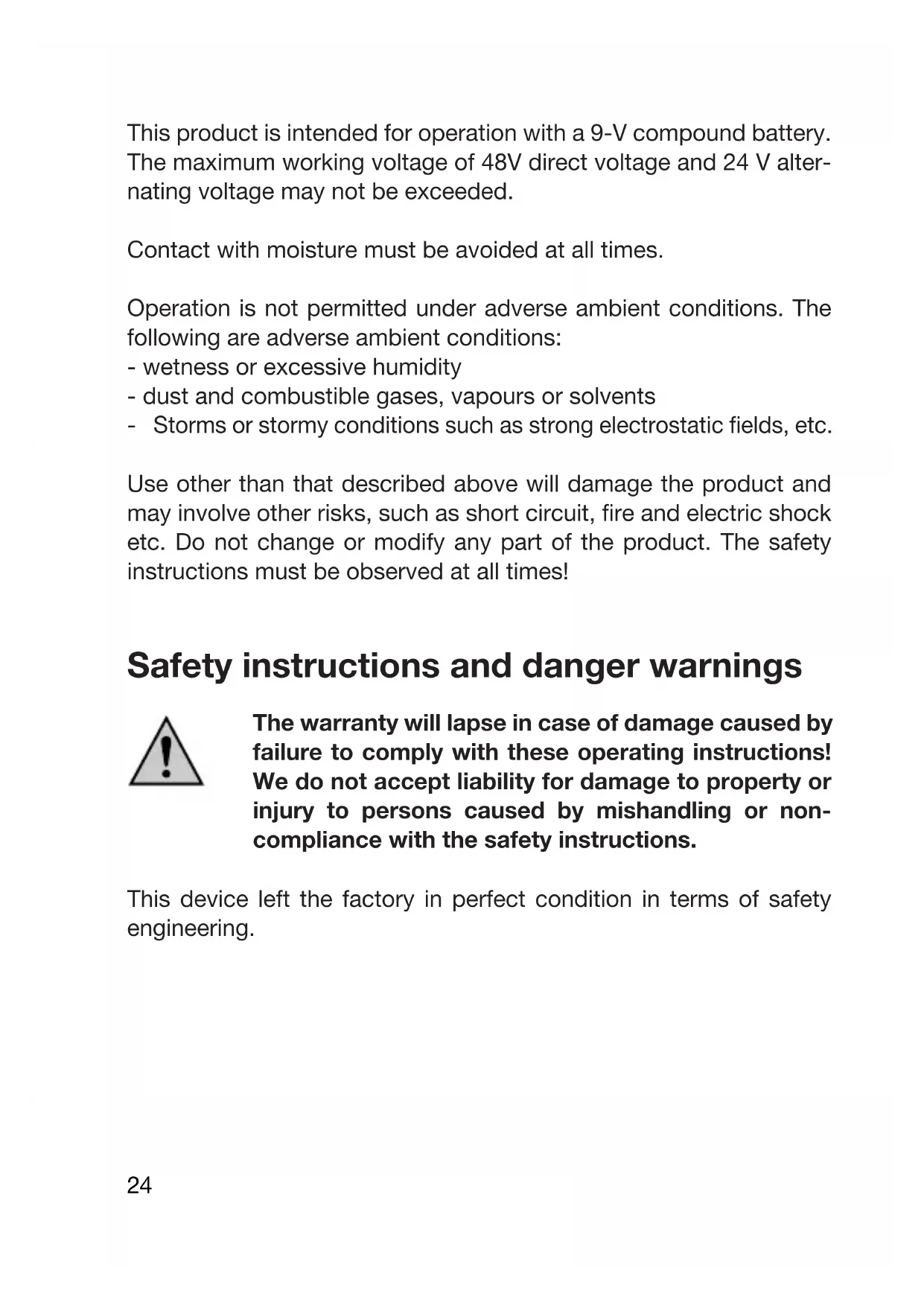
Diagram showing connections between a handheld device, multiple earphones, and a handheld device with wireless signals.Net probe (1)
Cable tracing / identification
The test signal which is transmitted from the bet toner can be received using the net probe. The signal received is reproduced on the built-in loudspeaker (8).
In a loud environment, an optional mono-earphone with a 2.5-mm jack plug can be connected to the net probe (jack 5). To activate this output, switch the slide switch (3) to the position "EAR".

Do not use the net probe on cable on which voltages greater than 24V AC / 48 VDC are or could be existent (danger to life!). Make sure of this before commencing the test.
To trace the signal, proceed as follows.
- Slide the mode switch (14) on the side to the "TRACE" position for signal tracing.
- Press the test key (9) and the net probe will be activated. Hold this pressed down during the cable tracing.
- Signalisation takes place optically over the signal display (11) and acoustically over the loudspeaker (8)
- Now set the desired signal volume on the volume control (10).
- Guide the test tip (2) beginning with the signal transmitter (16) parallel to the course of the cable. The volume must remain constant if the cable tracing is correct
- If you wish to identify a certain cable end, you can select from three test possibilities.
- Search without contact with the test tip (2)
- Contact-search through the RJ45 jack (4) at the side
- Contact-search through contacts (6) at the back
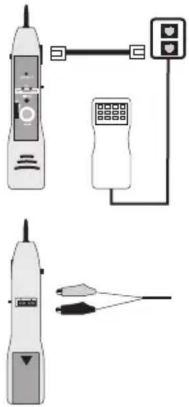
Cable test for analogue telephone cables
Analogue telephone cables can also be checked for their condition on the net probe.
The status is displayed over two light diodes.

Do not use the net probe on cables on which voltages greater than 24V AC / 48 VDC are or could be existent (danger to life!). Make sure of this before commencing the test.
Proceed as follows for the cable test:
- Slide the switch (14) on the side to the "TEL" position for signal the telephone cable test.
- Connect the net probe through the built-in RJ45 jack (4) t4o an optional RJ11/RJ45 connecting cable and a telephone socket or
- Connect the two telephone cables to the test connections (6) on the back, La to - / Lb to +.
- The test button (9) may not be pressed.
natural_image
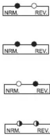
Illustration of a mobile phone with connected devices and a cable, no text or symbols present- The status displays have the following significance: The green LED flashes. voltage exists, polarity is correct.
The green and yellow LED flashes. Alternating voltage is pending.
The yellow LED flashes. The polarity is incorrect
The green and yellow LED flashes. Bell voltage is pending.
flowchart
graph TD
    A["NRM."] --> B["REV."]
    C["NRM."] --> D["REV."]
    E["NRM."] --> F["REV."]
    G["NRM."] --> H["REV."]
Disposal of flat batteries / accumulators
You, as the ultimate customer, are legally obliged (Ordinance regarding Flat Batteries) to return all used batteries and accumulators; disposal in the household waste is prohibited!

Batteries / accumulators which contain hazardous substances are marked by the symbols on the side. These symbols also indicate that it is prohibited to dispose of these batteries in the household waste.

The names for the decisive heavy metals are: Cd = cadmium, Hg = mercury, Pb = lead. You can return flat batteries / accumulators free of charge to the collection points in your community, our branches or anywhere else where batteries or accumulators are sold.
You thus fulfil the legal requirements and make your contribution to the protection of the environment!

Never operate the test device when it is open. Do not leave flat batteries in the device. Even batteries protected against leaking can corrode and thus release chemicals which may be detrimental to your health or destroy the battery compartment.
Batteries have no place in the hands of children. Do not throw batteries into the fire. This is risk of explosion!
Servicing and cleaning
Use a clean, lint-free, antistatic and dry cloth to clean the outside of the device without abrasive or chemical agents or detergents containing solvents.
Test tip of the net probe can be replaced with a new one if it is badly worn.
Proceed as follows for replacement
- Looking from the front, screw the tip in the anticlockwise direction out of the socket.
- Insert the enclosed replacement tip and screw the new tip firmly up to the stop.
- The net probe is ready for use again.
Disposal
If the product is no longer functional and can no longer be repaired, dispose of it in accordance with the relevant statutory regulations.
Technical data
| Net toner Net probe | ||
| Voltage supply 9-V compound battery battery battery | ||
| Current consumption max. 17 mA max. 50 mA | ||
| Voltage protection 48VDC / 24VAC 48VDC / 24VAC | ||
| Signal frequency Hi alternating500 – 781 HzLo alternating446 – 657 Hz | ||
| Voltage for: 9V at 600 OhmLanguage connection | ||
| Signal volume 30 dB | ||
| Resistance of the test tip | 30 Ohm | (Plastic tip) |
| Dimensions 125 x 68 x 26 (LxWxH mm): | 210 x 40 x 28 | |
| Mass (without battery) 120g 90 g | ||
| Work environment | 0°C to 40°C | |
F Introduction
Cher Client ,