
695520 - Electric saw MILWAUKEE - Free user manual and instructions
Find the device manual for free 695520 MILWAUKEE in PDF.

| Product Type | Slide Compound Miter Saw |
| Brand | Milwaukee |
| Model | 695520 |
| Power | 120 V AC, 15 A |
| No-load speed | 3,200 rpm |
| Blade diameter | 305 mm (12") |
| Blade arbor | 5/8" (15.875 mm) |
| Max blade thickness | 3.1 mm (1/8") |
| Cut capacity at 90° (height x width) | 166.4 mm x 342.9 mm |
| Cut capacity at 45° (height x width) | 166.4 mm x 241.6 mm |
| Miter angle range | 55° left to 60° right |
| Miter stops | 0°, 15°, 22.5°, 31.62°, 45°, 60° |
| Bevel angle range | 0° to 45° left, 0° to 48° right |
| Bevel stops | 0°, 22.5°, 33.85°, 45° |
| Electric brake | Yes, stops in about 4 seconds |
| Electronic feedback | Yes, maintains speed and torque |
| Integrated lighting | 2 high-power lamps (GE 193) |
| Dust collector | Yes, with dust bag |
| Grounding | Yes, three-prong plug |
| Warranty | 5 years |
Frequently Asked Questions - 695520 MILWAUKEE
User questions about 695520 MILWAUKEE
0 question about this device. Answer the ones you know or ask your own.
Ask a new question about this device
Download the instructions for your Electric saw in PDF format for free! Find your manual 695520 - MILWAUKEE and take your electronic device back in hand. On this page are published all the documents necessary for the use of your device. 695520 by MILWAUKEE.
USER MANUAL 695520 MILWAUKEE
natural_image
Technical line drawing of a mechanical device with no visible text or symbolsCat. No. / No de cat.
6955-20
12" SLIDING DUAL BEVEL MITER SAW WITH DIGITAL FINE ADJUST SCIE À ONGLETS COULISSANTE À DOUBLE BISEAU DE 305 mm (12") AVEC FONCTION DE RÉGLAGE NUMÉRIQUE PRÉCIS SIERRA INGLETEADORA DE BISEL DOBLE DESLIZABLE DE 305 mm (12") CON AJUSTE FINO DIGITAL

WARNING To reduce the risk of injury, user must read and understand operator's manual.
Read all safety warnings, instructions, illustrations and specifica-
tions provided with this power tool. Failure to follow all instructions listed below may result in electric shock, fire and/or serious injury. Save all warnings and instructions for future reference. The term "power tool" in the warnings refers to your mains-operated (corded) power tool or battery-operated (cordless) power tool.
WORK AREA SAFETY
- Keep work area clean and well lit. Cluttered or dark areas invite accidents.
- Do not operate power tools in explosive atmospheres, such as in the presence of flammable liquids, gases or dust. Power tools create sparks which may ignite the dust or fumes.
- Keep children and bystanders away while operating a power tool. Distractions can cause you to lose control.
ELECTRICAL SAFETY
- Power tool plugs must match the outlet. Never modify the plug in any way. Do not use any adapter plugs with earthed (grounded) power tools. Unmodified plugs and matching outlets will reduce risk of electric shock.
- Avoid body contact with earthed or grounded surfaces, such as pipes, radiators, ranges and refrigerators. There is an increased risk of electric shock if your body is earthed or grounded.
- Do not expose power tools to rain or wet conditions. Water entering a power tool will increase the risk of electric shock.
- Do not abuse the cord. Never use the cord for carrying, pulling or unplugging the power tool. Keep cord away from heat, oil, sharp edges or moving parts. Damaged or entangled cords increase the risk of electric shock.
- When operating a power tool outdoors, use an extension cord suitable for outdoor use. Use of a cord suitable for outdoor use reduces the risk of electric shock.
- If operating a power tool in a damp location is unavoidable, use a ground fault circuit interrupter (GFCI) protected supply. Use of an GFCI reduces the risk of electric shock.
PERSONAL SAFETY
- Stay alert, watch what you are doing and use common sense when operating a power tool. Do not use a power tool while you are tired or under the influence of drugs, alcohol or medication. A moment of inattention while operating power tools may result in serious personal injury.
- Use personal protective equipment. Always wear eye protection. Protective equipment such as a dust mask, non-skid safety shoes, hard hat or hearing protection used for appropriate conditions will reduce personal injuries.
- Prevent unintentional starting. Ensure the switch is in the off-position before connecting to power source and/or battery pack, picking up or carrying the tool. Carrying power tools with your finger on the switch or energizing power tools that have the switch on invites accidents.
- Remove any adjusting key or wrench before turning the power tool on. A wrench or a key left attached to a rotating part of the power tool may result in personal injury.
- Do not overreach. Keep proper footing and balance at all times. This enables better control of the power tool in unexpected situations.
- Dress properly. Do not wear loose clothing or jewelry. Keep your hair and clothing away from moving
parts. Loose clothes, jewelry or long hair can be caught in moving parts.
- If devices are provided for the connection of dust extraction and collection facilities, ensure these are connected and properly used. Use of dust collection can reduce dust-related hazards.
- Do not let familiarity gained from frequent use of tools allow you to become complacent and ignore tool safety principles. A careless action can cause severe injury within a fraction of a second.
POWER TOOL USE AND CARE
- Do not force the power tool. Use the correct power tool for your application. The correct power tool will do the job better and safer at the rate for which it was designed.
- Do not use the power tool if the switch does not turn it on and off. Any power tool that cannot be controlled with the switch is dangerous and must be repaired.
- Disconnect the plug from the power source and/or remove the battery pack, if detachable, from the power tool before making any adjustments, changing accessories, or storing power tools. Such preventive safety measures reduce the risk of starting the power tool accidentally.
- Store idle power tools out of the reach of children and do not allow persons unfamiliar with the power tool or these instructions to operate the power tool. Power tools are dangerous in the hands of untrained users.
- Maintain power tools and accessories. Check for misalignment or binding of moving parts, breakage of parts and any other condition that may affect the power tool's operation. If damaged, have the power tool repaired before use. Many accidents are caused by poorly maintained power tools.
- Keep cutting tools sharp and clean. Properly maintained cutting tools with sharp cutting edges are less likely to bind and are easier to control.
- Use the power tool, accessories and tool bits etc. in accordance with these instructions, taking into account the working conditions and the work to be performed. Use of the power tool for operations different from those intended could result in a hazardous situation.
- Keep handles and grasping surfaces dry, clean and free from oil and grease. Slippery handles and grasping surfaces do not allow for safe handling and control of the tool in unexpected situations.
SERVICE
- Have your power tool serviced by a qualified repair person using only identical replacement parts. This will ensure that the safety of the power tool is maintained.
SPECIFIC SAFETY RULES FOR MITER SAW
- Miter saws are intended to cut wood or wood-like products, they cannot be used with abrasive cut-off wheels for cutting ferrous material such as bars, rods, studs, etc. Abrasive dust causes moving parts such as the lower guard to jam. Sparks from abrasive cutting will burn the lower guard, the kerf insert and other plastic parts.
- Use clamps to support the workpiece whenever possible. If supporting the workpiece by hand, you must always keep your hand at least 100 mm from either side of the saw blade. Do not use this saw to cut pieces that are too small to be securely clamped or held by hand. If your hand is placed too close to the saw blade, there is an increased risk of injury from blade contact.
- The workpiece must be stationary and clamped or held against both the fence and the table.
Do not feed the workpiece into the blade or c"freehand" in any way. Unrestrained or moving workpieces could be thrown at high speeds, causing injury.
- Push the saw through the workpiece. Do not pull the saw through the workpiece. To make a cut, raise the saw head and pull it out over the workpiece without cutting, start the motor, press the saw head down and push the saw through the workpiece. Cutting on the pull stroke is likely to cause the saw blade to climb on top of the workpiece and violently throw the blade assembly towards the operator.
- Never cross your hand over the intended line of cutting either in front or behind the saw blade. Supporting the workpiece “cross handed” i.e. holding the workpiece to the right of the saw blade with your left hand or vice versa is very dangerous.
- Do not reach behind the fence with either hard closer than 100 mm from either side of the saw blade, to remove wood scraps, or for any other reason while the blade is spinning. The proximity of the spinning saw blade to your hand may not be obvious and you may be seriously injured.
- Inspect your workpiece before cutting. If the workpiece is bowed or warped, clamp it with the outside bowed face toward the fence. Always make certain that there is no gap between the workpiece, fence and table along the line of the cut. Bent or warped workpieces can twist or shift and may cause binding on the spinning saw blade while cutting. There should be no nails or foreign objects in the workpiece.
- Do not use the saw until the table is clear of all tool wood scraps, etc., except for the workpiece. Small debris or loose pieces of wood or other objects that contact the revolving blade can be thrown with high speed.
- Cut only one workpiece at a time. Stacked multiple workpieces cannot be adequately clamped or braced and may bind on the blade or shift during cutting.
- Ensure the miter saw is mounted or placed on a level, firm work surface before use. A level and firm work surface reduces the risk of the miter saw becoming unstable
- Plan your work. Every time you change the bevel of mitre angle setting, make sure the adjustable fence is set correctly to support the workpiece and will not interfere with the blade or the guarding system. Without turning the tool "ON" and with no workpiece on the table, move the saw blade through a complete simulated cut to assure there will be no interference or danger of cutting the fence.
- Provide adequate support such as table extensions saw horses, etc. for a workpiece that is wider or longer than the table top. Workpieces longer or wider than the miter saw table can tip if not securely supported. If the cut-off piece or workpiece tips, it can lift the lower guard or be thrown by the spinning blade.
- Do not use another person as a substitute for a table extension or as additional support. Unstable support for the workpiece can cause the blade to bind or the workpiece to shift during the cutting operation pulling you and the helper into the spinning blade.
- The cut-off piece must not be jammed or pressed by any means against the spinning saw blade. If confined, i.e. using length stops, the cut-off piece could get wedged against the blade and thrown violently
- Always use a clamp or a fixture designed to properly support round material such as rods or tubing. Rods have a tendency to roll while being cut, causing the blade to "bite" and pull the work with your hand into the blade.
- Let the blade reach full speed before contacting the workpiece. This will reduce the risk of the workpiece being thrown.
If the workpiece or blade becomes jammed, turn the mitre saw off. Wait for all moving parts to stop and disconnect the plug from the power source and/or remove the battery pack. Then work to free the jammed material. Continued sawing with a jammed workpiece could cause loss of control or damage to the miter saw.
- After finishing the cut, release the switch, hold the saw head down and wait for the blade to stop before removing the cut-off piece. Reaching with your hand near the coasting blade is dangerous.
- Hold the handle firmly when making an incomplete cut or when releasing the switch before the saw head is completely in the down position. The braking action of the saw may cause the saw head to be suddenly pulled downward, causing a risk of injury.
d Do not carry tool by workpiece supports. Supports could bend or break, causing tool to drop. Only carry tool by carrying handles.
- WARNING To reduce the risk of injury in applications that produce a considerable amount of dust, use an OSHA compliant dust extraction solution in accordance with the solution's operating instructions.
• Always use common sense and be cautious when using tools. It is not possible to anticipate every situation that could result in a dangerous outcome. Do not use this tool if you do not understand these operating instructions or you feel the work is beyond your capability; contact Milwaukee Tool or a trained professional for additional information or training.
- Maintain labels and nameplates. These carry important information. If unreadable or missing, contact a MILWAUKEE service facility for a free replacement.
WARNING Some dust created by power sanding, sawing, grinding, drilling, and other construction activities contains chemicals known to cause cancer, birth defects or other reproductive harm. Some examples of these chemicals are:
- lead from lead-based paint
• crystalline silica from bricks and cement and other masonry products, and
• arsenic and chromium from chemically-treated lumber. Your risk from these exposures varies, depending on how often you do this type of work. To reduce your exposure to these chemicals: work in a well ventilated area, and work with approved safety equipment, such as those dust masks that are specially designed to filter out microscopic particles.
SYMBOLOGY

Insulated


UL Listing Mark for Canada and U.S.
Always keep hands away from the path of the saw blade
No Hands Zone - Keep hands out of the No Hands Zone at all times during use. Contact with blade will result in serious injury.
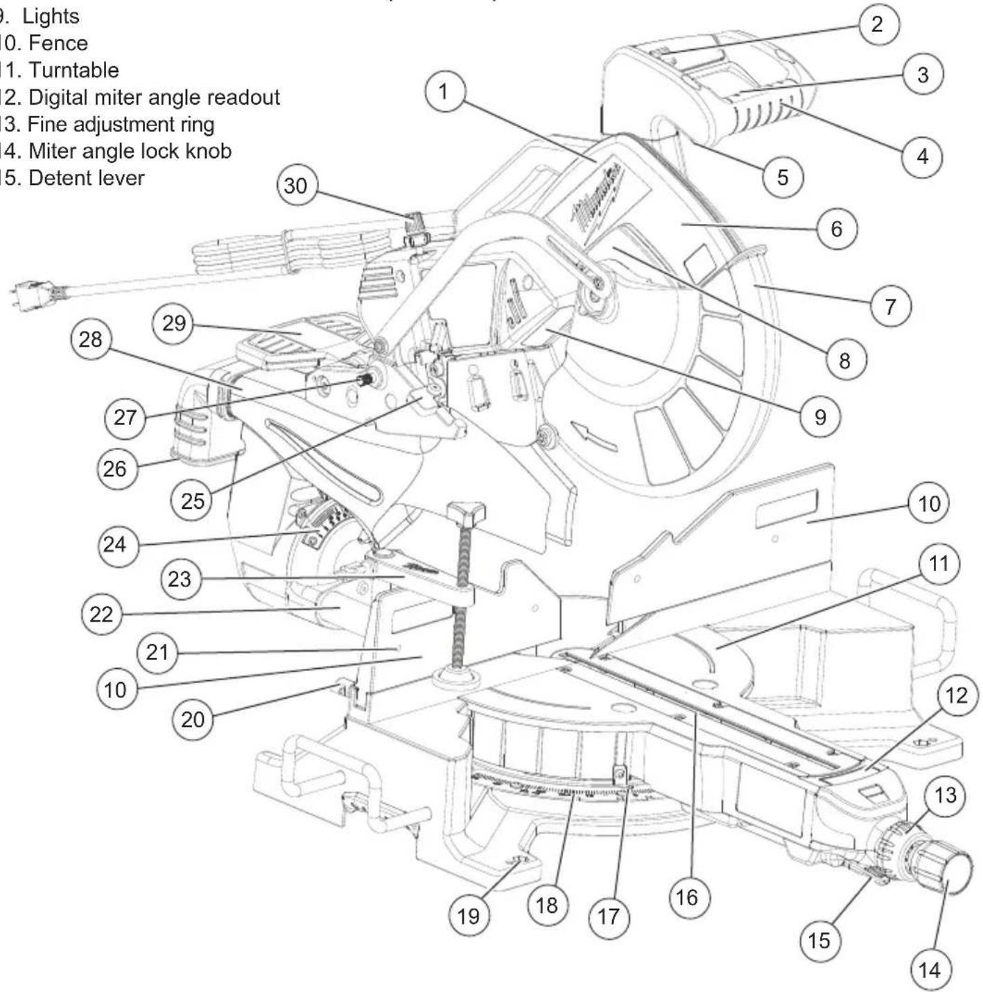
FUNCTIONAL DESCRIPTION
- Saw head
- Light on/off switch
- Trigger lock
- Upper handle
- On/Off trigger
- Upper guard
- Lower guard
- Guard bracket
- Lights
- Fence
- Turntable
- Digital miter angle readout
- Fine adjustment ring
- Miter angle lock knob
-
Detent lever
-
Adjustable kerf plates
- Miter angle pointer
- Miter angle scale
- Mounting holes (4)
- Fence lock knob
- Face board mounting holes (4)
- Slide rails
-
Workpiece clamp
-
Bevel angle scale
- Depth stop paw
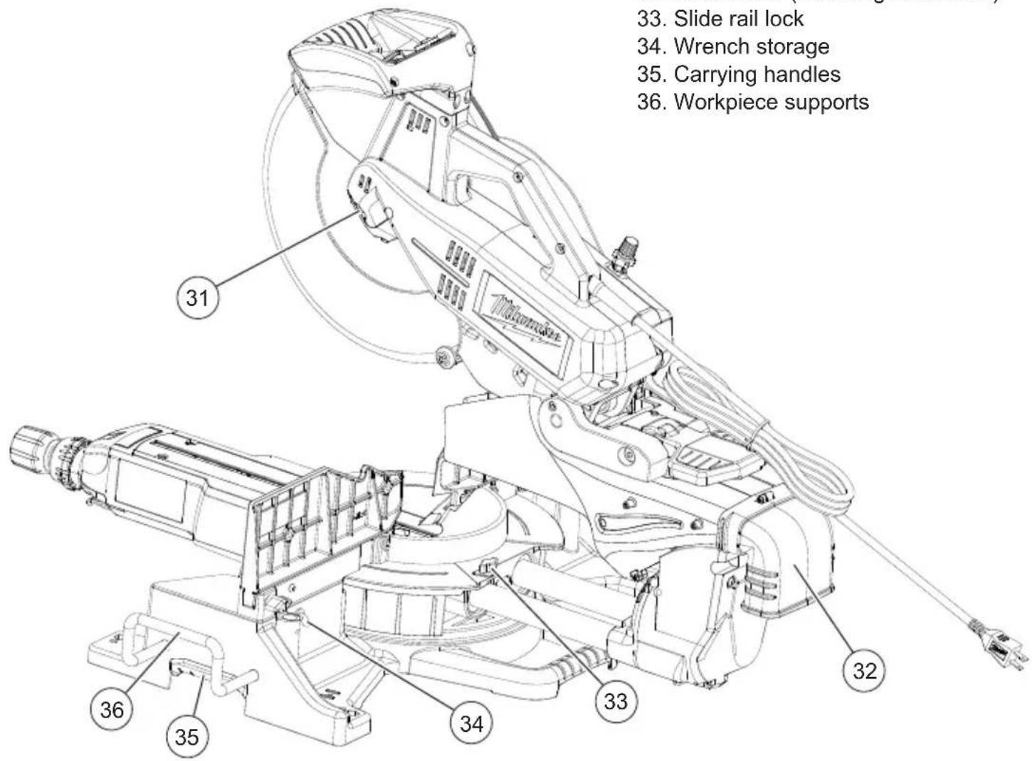
- Dust ejection port
- Head lock-down pin
- Dust chute
- Bevel adjustment lever
- Depth stop adjustment knob
SPECIFICATIONS
Cat. No....6955-20
Volts....120 AC
Amps 15
No Load RPM 3200
Arbor Size 5/8"
Blade Size 12"
Blade Thickness (Kerf) ...... Max 1/8"
Weight 65 lb
CAPACITIES
Miter Cuts
| Max Height at 90° | 6.55" H at 2.10" W |
| Max Height at 45° | 6.55" H at .40" W |
| Max Width at 90° | 13.5" W at 4.02" H |
| Max Width at 45° | 9.51" W at 4.02" H |
| Compound Cuts | 45 Miter and 45° Bevel |
| Left Bevel | 9.51" W at 2.25" H |
| Right Bevel | 9.51" W at 1.9" H |
EXTENSION CORDS
Grounded tools require a three wire extension cord. Double insulated tools can use either a two or three wire extension cord. As the distance from the supply outlet increases, you must use a heavier gauge extension cord. Using extension cords with inadequately sized wire causes a serious drop in voltage, resulting in loss of power and possible tool damage. Refer to the table shown to determine the required minimum wire size. The smaller the gauge number of the wire, the greater the capacity of the cord. For example, a 14 gauge cord can carry a higher current than a 16 gauge cord. When using more than one extension cord to make up the total length, be sure each cord contains at least the minimum wire size required. If you are using one extension cord for more than one tool, add the nameplate amperes and use the sum to determine the required minimum wire size.
Guidelines for Using Extension Cords
- If you are using an extension cord outdoors, be sure it is marked with the suffix "W-A" ("W" in Canada) to indicate that it is acceptable for outdoor use.
- Be sure your extension cord is properly wired and in good electrical condition. Always replace a damaged extension cord or have it repaired by a qualified person before using it.
- Protect your extension cords from sharp objects, excessive heat and damp or wet areas.
| Recommended Minimum Wire Gauge For Extension Cords* | |||||
| Nameplate Amps | Extension Cord Length | ||||
| 25' 50' | 75' 100' | 150' | |||
| 0 - 2.0 | 18 | 18 | 18 | 18 | 16 |
| 2.1 - 3.4 | 18 | 18 | 18 | 16 | 14 |
| 3.5 - 5.0 | 18 | 18 | 16 | 14 | 12 |
| 5.1 - 7.0 | 18 | 16 | 14 | 12 | 12 |
| 7.1 - 12.0 | 16 | 14 | 12 | 10 | -- |
| 12.1 - 16.0 | 14 | 12 | 10 | -- | -- |
| 16.1 - 20.0 | 12 | 10 | -- | -- | -- |
* Based on limiting the line voltage drop to five volts at 150% of the rated amperes.
GROUNDING
WARNING
Improperly connecting the grounding wire can result in the risk of electric shock. Check with a qualified electrician if you are in doubt as to whether the outlet is properly grounded. Do not modify the plug provided with the tool. Never remove the grounding prong from the plug. Do not use the tool if the cord or plug is damaged. If damaged, have it repaired by a MILWAUKEE service facility before use. If the plug will not fit the outlet, have a proper outlet installed by a qualified electrician.
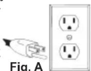
Grounded Tools (Three-Prong Plugs)
Tools marked “Grounding Required” have a three wire cord and three prong grounding plug. The plug must be connected to a properly grounded outlet (See Figure A). If the tool should electrically malfunction or break down, grounding provides a low resistance path to carry electricity away from the user, reducing the risk of electric shock.
The grounding prong in the plug is connected through the green wire inside the cord to the grounding system in the tool. The green wire in the cord must be the only wire connected to the tool's grounding system and must never be attached to an electrically "live" terminal.
Your tool must be plugged into an appropriate outlet, properly installed and grounded in accordance with all codes and ordinances. The plug and outlet should look like those in Figure A.
Double Insulated Tools (Two-Prong Plugs) Tools marked "Double Insulated" do not require grounding. They have a special double insulation system which satisfies OSHA requirements and complies with the applicable standards of Underwriters Laboratories, Inc., the Canadian Standard Association and the National Electrical Code. Double Insulated tools may be used in either of the 120 volt outlets shown in Figures B and C. Fig. B Fig. C
FEATURES
Miter system
The MILWAUKEE 6955-20 Miter Saw uses a heavy duty steel plate with detents (stops). This steel plate is extremely durable and provides for repeatable accuracy at each detent. The miter angle can be set using detents for commonly cut angles at 0^ , 15^ , 22.5^ 31.62^ , 45^ Right and Left and 60^ Right. The 6955-20 has a miter range from 55^ on the left to 60^ on the right. An industrial grade bearing allows the turntable to be quickly and accurately adjusted to any angle across the miter range.
Miter Angle Fine Adjust
In certain finish carpentry applications like casing a window or door, it is necessary to compensate for a non-square situation by making a precision miter angle adjustment to the turntable. The Milwaukee miter angle fine adjust system makes this process quick and easy, especially when the saw is positioned near a miter detent (stop).
Digital Miter Angle Readout
The Milwaukee 6955-20 has a Digital Miter Angle Readout at the front of the turntable that displays the miter angle of the turntable to a resolution of 0.1^ . The Digital Miter Angle Readout is based on the mechanical accuracy of the miter angle detent plate. It calibrates itself each time the turntable is placed in a miter detent and it requires no adjustment.
Using the Miter Angle Fine Adjust in conjunction with the Digital Miter Angle Readout, it is easy to make accurate minor angle adjustments anywhere along the miter range. Using these systems together makes it easy to re-position the turntable and repeat any miter angle setting.
When the turntable is positioned at a LEFT miter angle the digital readout will display with a (-) symbol in front of the angle (for example: -22.5^ or -44.7^ ). When the turntable is positioned at a RIGHT miter angle the digital readout will display as follows: 22.5^ or 44.7^ .
Dual Bevel Adjustment System
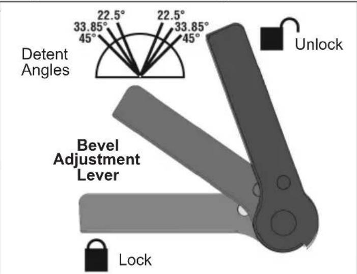
The Dual Bevel Adjustment System allows for quick and accurate bevel adjustments to either the Right or the Left. The bevel angle can be set using detents (stops) for the following commonly cut angles 0^ , 22.5^ , 33.85^ , 45^ Right and Left. The bevel mechanism also has several degrees of overtravel beyond 45^ on both the left and right.
Electronic Feedback Control Circuit
The Electronic Feedback Control Circuit (EFCC) helps improve the operation and life of the tool. It allows the tool to maintain constant speed and torque between no-load and load conditions. The soft start reduces the amount of torque reaction at startup to the tool and the user. It gradually increases the motor speed up from zero to the top no-load speed.
Electric Brake
The electric brake engages when the trigger is released, causing the blade to stop and allowing you to proceed with your work. WARNING! The brake is not a substitute for the guards, so it is essential to always wait for the blade to stop completely before removing the blade from the kerf. Generally the saw blade stops in four to five seconds. However, there may be a delay between the time the trigger is released and the time the brake engages. Occasionally the brake may miss completely. If the brake misses frequently, the saw needs servicing by an authorized MILWAUKEE service station.
Lights
The Milwaukee 6955-20 Miter Saw has two high power lights positioned on either side of the blade to illuminate the workpiece cutting area so that it is easy to see blade approach the cutting line. An ON / OFF switch for the lights is conveniently located on the trigger handle. The bulb is designed to provide several years of service. Uses standard bulb size GE 193.
Dust Management System
The Milwaukee 6955-20 Miter Saw dust collection system uses a large dust chute on both sides of the blade to capture and direct dust to back of the saw. The saw comes with a Dust Elbow and a Dust Bag that attach to the back of the Dust Chute. The dust bag has a zipper located on the bottom of the bag that makes it easy to empty. When using the saw on a stand, the dust bag zipper can be left open to allow the waste to fall into a waste container.
Carrying Handles
For ease of transporting, multiple carrying handles are provided, one on each side of the table and one on top of the saw head. Always lock the saw head down when transporting. WARNING! Do not carry tool by workpiece supports.
WARNING
To reduce the risk of injury, always unplug tool before attaching or re-
moving accessories or making adjustments. Use only specifically recommended accessories. Others may be hazardous.
Installing the Workpiece Supports
The workpiece supports are used as support extensions for cutting longer workpieces. To install, insert a support into the holes in the side of the table with the U-bend pointing up. Tighten the screws from beneath the saw to secure. WARNING! Do not carry tool by workpiece supports.
Adjusting the Miter Saw
The 6955-20 Miter Saw is fully adjusted at the factory. If it is not accurate due to shipping and handling, please follow these steps to accurately set up your saw. Once the saw is properly adjusted, it should remain accurate under normal jobsite and transportation conditions.
Squaring the Blade (90°) to the Fence (0° Miter)
- Unplug saw
- Place a square against the fence and blade and ensure that the square is not touching blade teeth as this will cause an inaccurate measurement
- Loosen the miter lock knob and move the saw to the 0^ miter position. Do not tighten the lock knob.
- If the saw blade is not exactly perpendicular to the fence, use the supplied wrench to loosen the screws that hold the miter scale to the base. Move the scale left or right until the blade is perpendicular to the fence. Use the square to verify that the blade is perpendicular to the fence. Retighten the screws.
- Loosen the miter pointer adjustment screw and reposition the pointer the so that it indicates exactly zero. Once the pointer is properly positioned, retighten the miter pointer adjustment screw.
Squaring the Blade (90°) to the Table (0° Bevel)
- Unplug saw
- Place a square against the table and blade and ensure that the square is not touching blade teeth as this will cause an inaccurate measurement.
- Remove the 6 screws holding the dust chute together.
- Move the bevel adjustment lever to the middle position and wedge in a tool (screw driver etc.) so the handle stay in the middle position. Move the saw head so that the bevel detent mechanism locks into the 0^ bevel detent.
- Loosen 2 screws (T25) on the front of the bevel arm, these screws are used to clamp the detent body.
- Using a T25 wrench you can adjust the bevel setting of the blade-to-table. Clockwise tilts blade to the right, counterclockwise tilts blade to the left.
- When you have the blade set to the 0^ bevel, torque the 2 screws to 85-100 in lbs.
- Remove the tool used to wedge the bevel adjustment lever.
- Move the bevel adjustment lever to "lock".
- Reassemble the dust chute sides, tightening the 6 screws securely.
- If necessary, loosen the left and right bevel pointer adjustment screws and reposition the pointers the so that they indicates exactly zero. Once the pointers are properly positioned, retighten the bevel pointer adjustment screw.
Mounting the Miter Saw
To prevent the tool from sliding, falling or tipping during operation, the saw can be mounted to a supporting surface such as a level, sturdy work table or bench. Position the saw and workbench to allow adequate room for cross-cutting long workpieces. To mount the saw, insert fasteners through the holes in the corners of the saw base.
Installing the Dust Bag
Use the dust bag to collect or divert sawdust. Insert the dust elbow into the dust chute on the back of the saw. Then, attach the dust bag by hooking it onto the dust elbow. Always empty the dust bag before storing and frequently during use.
Raising and Lowering the Saw Head
The saw head must be locked down for transporting and storing the tool. The tool is shipped with the saw head locked down. To unlock it, press and hold down the saw head and simultaneously pull out the lock down pin. To lock the saw head, press and hold down the saw head and then push in the lock down pin.
Locking and Unlocking the Sliding Mechanism
Always lock the sliding mechanism before transporting or storing the saw. To unlock it, loosen the slide rail lock by turning it counterclockwise. To lock it, tighten the slide rail lock by turning it clockwise.
Lock-Off
There is a hole in the trigger through which a padlock will fit to lock the tool when it is not in use. Use a padlock with a 1/4" shackle and always unplug the tool before installing it (padlock not supplied with tool).
Selecting the Correct Miter Saw Blade
Use only sliding miter saw blades with the MILWAUKEE Sliding Dual Bevel Miter Saw. Saw blades with a 0° hook angle or a negative hook angle work well for Sliding Miter saws. A negative hook angle means that teeth tip away from the direction of rotation, and a 0° degree hook angle means that the teeth are in line with the center of the blade. A low or negative hook angle will slow the feed rate and will also minimize the blade's tendency to "climb" the material being cut.
Installing and Changing Blades
Always use clean, sharp blades because dull blades tend to overload the tool, bind and cause pinching. Use only 12" blades rated at least 5500 RPM.
-
Unplug the tool.
-
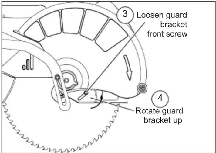
With the saw head up, use the wrench to loosen the guard bracket rear screw 1/4 turn using the wrench provided (1).
-
Raise the lower guard (2).

- Loosen (do not remove) the guard bracket front screw (3) until the guard bracket can be raised to expose the blade screw (4). Lower the lower guard until it rests on the guard bracket front screw. This will hold it up and out of the way during the blade change.
- Press in the spindle lock and rotate the spindle until the lock engages.
- Use the wrench to loosen and remove the left-hand thread blade screw clockwise.
- Remove the outer blade flange, blade, blade washer, and inner blade flange. Wipe the flanges, washer, and spindle to remove dust and debris. Inspect the parts for damage. Replace if needed.
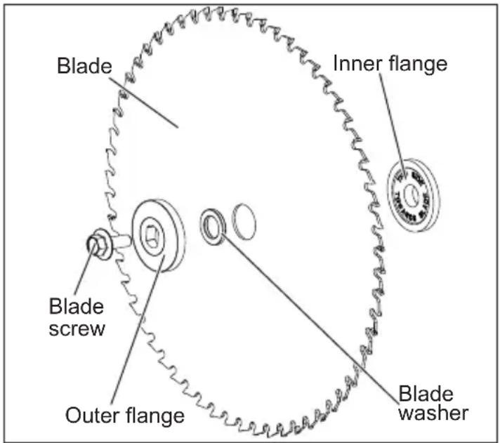
- Install the inner blade flange as shown.
- Insert the blade washer into the blade arbor hole.
- Match the arrow on the blade with the arrow on the lower guard. Slide the blade into the upper guard and onto the spindle.
- Install the outer blade flange.
- Press in the spindle lock and rotate the blade until the lock engages. Insert and securely tighten the blade screw counterclockwise with the wrench.
- Rotate the guard bracket into position and securely tighten the two screws. Return the wrench to the wrench holder.
- Lower the saw head and check the clearance between the blade and the adjustable kerf plates. Important: The lower guard must move freely. The blade should rotate freely (see "Adjusting the Kerf Plates").
Adjusting the Kerf Plates
Kerf plates reduce tear-out and splintering along the cut by providing edge support. Because blades vary in width, adjust the kerf plates with every blade change. Never make a cut without the adjustable kerf plates installed. The kerf plates can be set at their maximum width to accommodate all blade widths and bevel angles if tear-out and splintering are not a concern.
- Unplug the tool.
- Install the blade to be used. Each time the blade is changed, check to be sure the kerf plates are adjusted properly.
- Set the bevel angle. Each time the bevel is changed, check to be sure the kerf plates are adjusted properly.
- Loosen the six kerf plate adjusting screws.
- Lower the saw head to the full depth of cut (the point where the saw head will not lower any further).
- Slide the kerf plates to the desired spacing and tighten the six screws.
- Check to be sure the saw blade does not contact the kerf plates before starting the saw.
OPERATION
AWARNING To reduce the risk of injury, always wear proper eye protection marked to comply with ANSI Z87.1.
When working in dusty situations, wear appropriate respiratory protection or use an OSHA compliant dust extraction solution.
Always wait for the blade to stop completely and unplug the tool before changing accessories or making adjustments. Do not defeat the guards.
Do not carry tool by workpiece supports. Supports could bend or break, causing tool to drop. Only carry tool by carrying handles.
Using Face Boards (Zero Clearance Sub Fences)
There are face board mounting holes in the fences for attaching face boards. Face boards place distance between the fence and the workpiece, providing improved support for some workpieces. Workpiece splintering can be reduced by using face boards. As the width of the face board increases, the height of the workpiece which can be cut increases slightly (but the width capacity decreases slightly). Similarly, if you place a face board on the saw table and place a workpiece on top of the face board, you can cut a workpiece with greater width (but with less height).
Guards
The tool is shipped with both the upper and lower guard installed. The lower guard should cover the blade when the saw head is up and it should move freely and open automatically as the saw head is lowered into the workpiece. If the lower guard appears loose, sticks, or if it does not move to cover the blade when the saw head is up, tighten the guard bracket screws. If it still does not move freely, take the saw to an authorized service center for repairs. Do not attempt to open the guard further than the automatic action permits.
Select the Workpiece Carefully
Be cautious of pitchy, knotty, wet or warped workpieces. These materials are likely to create pinching conditions. Workpieces that bow and pinch may result in kick back. Inspect for and remove nails before cutting. Always keep blades clean and sharp; otherwise the blade produces a narrow kerf and is likely to be pinched by the workpiece. This tool is not recommended for cutting ferrous metals such as iron and steel. See Applications for a more complete list of materials.
Support the Workpiece Properly
Always support the workpiece during operation. Otherwise, the workpiece may pull up and into the saw. WARNING! Use clamps to support the workpiece whenever possible to keep hands far from the blade. Do not use this saw to cut pieces that are held by hand or too small to be securely clamped.
-
Use the Fence: Hold the workpiece flush against the fence to provide a straight path for the saw blade. This will help eliminate the tendency for the blade teeth to bind. The fence can be used as a support for miter, bevel and compound cuts. WARNING Keep hands out of the No Hands Zone at all times during use. Use the fence hand holds to ensure your hands do not enter the No Hands Zone
-
Use the workpiece clamp: Clamp the workpiece to the table with the included clamp. The clamp can be moved to either side of the table.
a. Insert the clamp bar into either clamp socket behind the fences.
b. Turn the clamp bar until it seats fully into the socket
c. Rotate the clamp around so the screw is above the table.
d. Tighten the clamp screw to secure the workpiece to the table.
- Use a C-clamp: Clamp the workpiece to the fence with a C-clamp.
Support of Longer Workpieces
Longer workpieces need support along their full length. If you are using the saw on a level work bench, prop up the workpiece to a height of 4-3/4" from the bottom of the saw feet. There are also many aftermarket work tables specifically designed for miter saws that provide supports for all types of workpieces.
Adjusting the Miter Angle
The miter angle can be set using detents for commonly cut angles, as well as finely adjusted to any angle. Use the miter angle pointer to adjust the turntable to any whole degree across the miter range. The digital miter angle readout shows the selected angle.
-
Loosen the miter angle lock knob.
-
To set the miter angle, pull up on the detent lever and rotate the turntable to the detent angle closest to the desired angle. The saw cuts miter angles from 55^ on the left to 60^ on the right. Detents are available at 0^ , 15^ , 22.5^ , 31.62^ , 45^ , and 60^ .
-
Tighten the miter angle lock knob to use the miter angle set at the detent before making a cut.
-
To make a fine adjustment to the miter angle:
A. Pull up and hold the detent lever. B. Push the fine adjustment ring forward until it locks to engage override.
C. Rotate the fine adjustment ring left or right until the desired angle is displayed on the digital miter angle readout. 14 turn = 1^ change in miter angle.
D. Tighten the miter angle lock knob to secure the table before making a cut.
E. Pull up on the detent lever to release the fine adjustment ring.
Adjusting the Bevel Angle
The bevel angle can be set using detents for commonly cut angles, as well as adjusted to any angle in between by using the bevel angle scale. The bevel mechanism also has several degrees of overtravel on both the left and right.
- Unplug the tool.
- To adjust the bevel angle, place one hand on the front handle for better control.
- Using the other hand, lift the bevel adjustment lever:
A. To use pre-set detents, lift the bevel adjustment lever half-way up (until it "clicks") to move the saw head left or right, with stops at pre-set detents.
B. To freely move the head, lift the bevel adjustment lever all the way up to freely move the saw head across the bevel range. - Pull or push the saw head to the desired angle using the bevel angle scale.
- Lock the bevel angle by pressing down the bevel adjustment lever before making a cut.
Adjusting the Depth of Cut
The depth of the cut can be adjusted for groove or rabbet cuts.
- Unplug the tool.
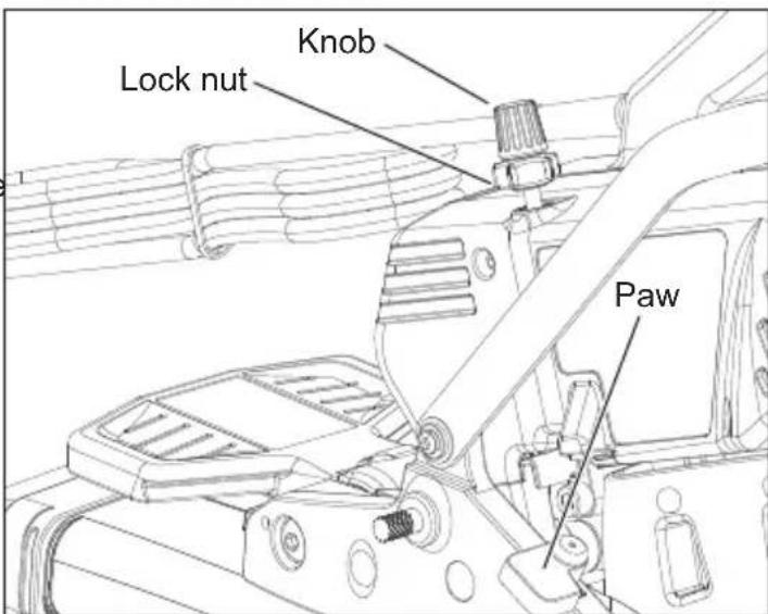
- To set the depth of cut, swivel the depth stop paw toward the front of the saw.
- Lower the saw head to the desired depth of cut.
- Rotate the depth stop adjustment knob until it contacts the paw. Lock in the depth using the lock nut.
- Plug in the tool and make a test cut to verify the depth of cut is correct.
- To remove the depth of cut limit, loosen the lock nut by turning counterclockwise and swivel the paw away from the front of the saw.
Adjusting the Fences
- Loosen the fence lock knobs.
- The fences can slide side-to-side to the desired position to allow for a bevel or compound miter cut.
- Always position the fences properly for maximum work support.
- Tighten the fence lock knobs securely before making a cut.
NOTE: If either fence has any movement forward to backward, tighten the fence set screw, located on the back of each fence slot.
Lights
Use the on/off switch to turn on the turntable lights before making a cut. Turn off the lights when cutting is complete.
WARNING To reduce the risk of injury, do not rely on the brake as a safety feature. Always wait until the blade stops completely before allowing anything near the blade. To reduce the risk of injury, make sure all adjustments are securely locked before making a cut.
Starting and Stopping the Tool
Always hold the trigger handle firmly because the starting and stopping action of the motor may cause the handle to move up or down slightly. WARNING! Always press down miter lock lever and tighten all adjustments prior to use. WARNING! Ensure hands are out of the No Hands Zone.
- To start the motor, push down the trigger lock and pull the trigger.
- To stop the motor, release the trigger. The electric brake will stop the blade in about 4 seconds. WARNING! The brake is not a substitute for the guards and could fail; always wait for the blade to stop completely before removing the blade from the workpiece. If the brake fails to stop the blade or misses frequently, return the tool to a MILWAUKEE service facility for repair.
Making a Chop Cut
The sliding mechanism can be locked to use the saw for chop cuts (cuts not requiring the use of the slide mechanism). Cut workpieces with chop cuts whenever possible. A chop cut is always faster and easier to make than a sliding cut.
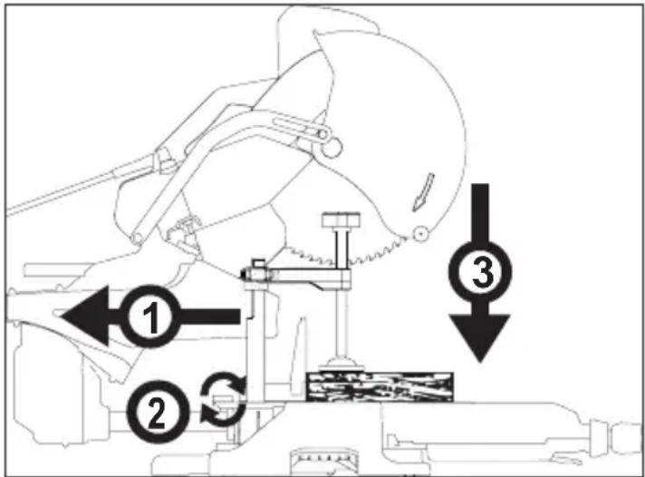
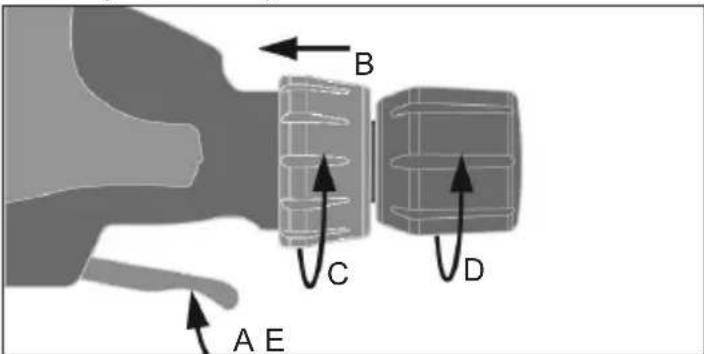
- Slide the saw head all the way back (1).
- Tighten the slide rail lock (2).
- Plug in the tool. Raise the saw head completely.
-
Select the desired angles following the steps in "Adjusting the Miter Angle" and "Adjusting the Bevel Angle".
-
Place the workpiece on the turntable and line up the cut.
- Support the workpiece using any of the methods described in "Support the Workpiece Properly".
- Start the motor. Wait a few seconds for the blade to reach full speed. Then gently lower the saw head into the workpiece all the way through the cut (3).
- Always allow the saw to do the work. Forcing the tool may stall or overheat the motor.
- After the cut is complete, release the trigger and wait for the blade to stop completely. Then gently raise the saw head and remove the workpiece. Always unplug the tool before retrieving loose cut-off pieces from inside the guard area.
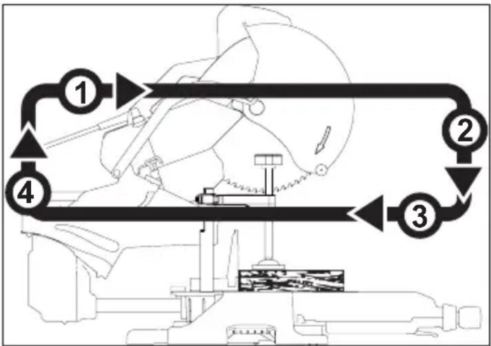
Making a Sliding Cut
Wider workpieces can be cut using the sliding mechanism.
flowchart
graph TD
    A["Component 1"] --> B["Component 2"]
    B --> C["Component 3"]
    C --> D["Component 4"]
    D --> A
    style A fill:#f9f,stroke:#333
    style B fill:#ccf,stroke:#333
    style C fill:#cfc,stroke:#333
    style D fill:#fcc,stroke:#333
- Make sure that the slide rail lock is loose and that the saw head moves freely back and forth.
- Select the desired angle following the steps in "Adjusting the Miter Angle" and "Adjusting the Bevel Angle".
- Place the workpiece on the turntable and line up the cut.
- Raise saw head and pull it out OVER the workpiece WITHOUT cutting (1).
- Start the motor. Wait a few seconds for the blade to reach full speed.
- Press down on saw head (2).
- Push saw through the cut (3).
- After the cut is complete, release the trigger and wait for the blade to stop completely. Then gently raise the saw head (4) and remove the workpiece. Always unplug the tool before retrieving loose cut-off pieces from inside the guard area.
APPLICATIONS
⚠ WARNING Do not cut stone, brick, concrete, or ferrous metals (iron, steel, stainless steel, or alloys of these metals) with this saw. Do not use abrasive wheels with this saw.
Dust created by cutting these materials and/or using abrasive cut-off wheels can jam the blade guard and possibly cause personal injury.
Recommended Materials and Applications
The following materials can be cut with the slide compound miter saw. There are many types of saw blades available. Always use the proper blade for the particular material and application.
- Wood - solid wood, plywood, particle board, MDF (medium density fiberboard), HDF (high density fiberboard), melamine laminated particle board, formica laminates, hardboard (masonite).
- Plastics - PVC, CPVC, ABS, solid surfacing materials (such as Corian®), and other plastic materials. When cutting plastic, avoid overheating the blade and blade teeth to prevent melting the workpiece.
• Nonferrous Metals - aluminum, brass, copper, and other non-ferrous materials.
Cutting Non-Square Materials Cutting Round (Cylindrical) Materials
"V" shaped blocks can be used to support round materials like closet rod and plastic pipe.
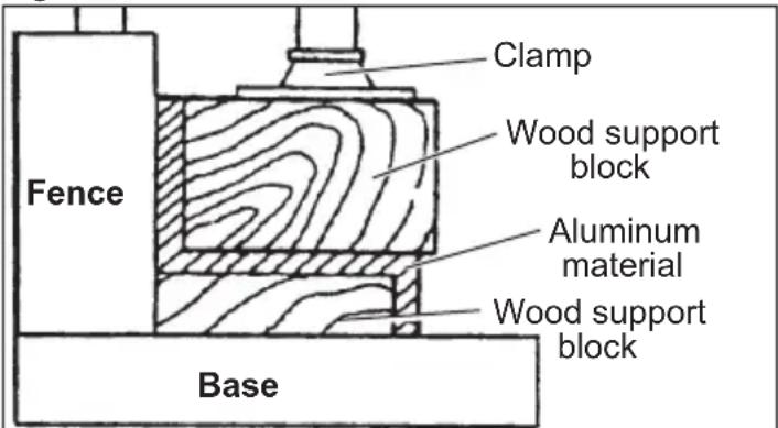
Aluminum Sash and Other Channel Type and Materials
Aluminum sash material can be supported with blocks to prevent it from deforming while it is being cut.
| Miter Range | Miter Detents (Stops) | |
| 0° to 55° Left0° to 60° Right | 0°, 15°, 22.5°, 31.62°, 45° Left0°, 15°, 22.5°, 31.62°, 45° Right | |
| Bevel Range | Bevel Detents (Stops) | |
| 0° to 45° Left0° to 48° Right | 0°, 22.5°, 33.85°, 45° Left0°, 22.5°, 33.85°, 45°, 48° Right | |
| Base Molding Capacity | Nested Crown Capacity | |
| 6" at 0°6" at 45° Left and Right | 6-5/8" | |
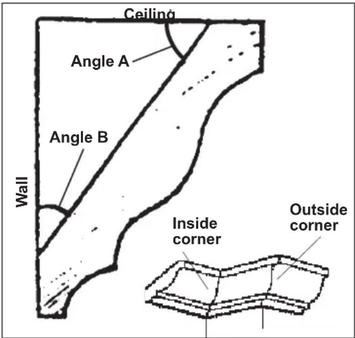
Two Methods for Cutting Crown Molding
The angles created on a piece of crown molding that fits flat against the ceiling and wall will, when added together, equal 90^ (A + B = 90^ ). The most common crown molding angles are :
52°/38°: A 52° angle against the ceiling (A) and a 38° angle against the wall (B). The miter saw has special miter settings at 31.6° left and right and a bevel setting at 33.9° to use when cutting 52°/38° crown molding flat on the miter saw table. These settings are identified with a diamond mark.
45°/45': A 45° angle against the ceiling (A) and a 45° angle against the wall (B). The miter saw has special miter settings at 35.3° left and right and a bevel setting at 30° to use when cutting 45°/45° crown flat on the miter saw table. These settings are identified with a black circle.
NOTE: Even though all of these angles are standard, rooms are very rarely constructed so the corners are exactly 90^ . You will need to “fine tune” these settings and make necessary adjustments to the cutting angles.
Cutting Crown Molding Flat on the Miter Saw Table
The advantage of cutting crown molding flat on the table is that it is easier to secure the molding at the correct cutting position. Also larger pieces of crown molding may be cut laying flat on the miter saw table.
-
Set the bevel and miter angles using the Crown Molding Miter Angles chart. Tighten the miter lock knob and the bevel lock knob.
-
Using the Positioning section below, correctly positions the molding.
NOTE: Always make a test cut on scrap material to confirm all angles are correct.
- Make the cut according to "Making a Chop Cut".
Cutting Crown Molding Angled Against the Fence (Nested – in position)
Always use a crown molding fence when cutting crown molding angled against the fence. When cutting crown molding angled against the fence does not require bevel settings. Small changes in the miter angle can be made without affecting the bevel angle. When using this method the saw can be quickly and easily adjusted for corners that are not 90° (square).
Positioning
Standard (U.S.) crown molding with 52° and 38° angles (set bevel angle to 33.85°)
Left side, inside corner
- Top edge of molding against fence
- Miter table set right 31.62
- Save left end of cut
Right side, inside corner
- Bottom edge of molding against fence
- Miter table set left 31.62
- Save left end of cut
Left side, outside corner
- Bottom edge of molding against fence
- Miter table set left 31.62
- Save right end of cut
Right side, outside corner
- Top edge of molding against fence
- Miter table set right 31.62
- Save right end of cut
Standard (U.S.) crown molding with 45° angles (set bevel angle to 0°)
Left side, inside corner
-
Top edge of molding against fence
-
Miter table set right 45
-
Save left end of cut
Right side, inside corner
-
Bottom edge of molding against fence
-
Miter table set left 45
-
Save left end of cut
Left side, outside corner
-
Bottom edge of molding against fence
-
Miter table set left 45
-
Save right end of cut
Right side, outside corner
-
Top edge of molding against fence
-
Miter table set right 45
-
Save right end of cut
MAINTENANCE
WARNING
To reduce the risk of injury, always unplug the tool before performing any maintenance. Never disassemble the tool. Contact a MILWAUKEE service facility for ALL repairs.
Maintaining Tools
Keep your tool in good repair by adopting a regular maintenance program. Inspect your tool for issues such as undue noise, misalignment or binding of moving parts, breakage of parts, or any other condition that may affect the tool operation. Return the tool to a MILWAUKEE service facility for repair. After six months to one year, depending on use, return the tool to a MILWAUKEE service facility for inspection.
WARNING
To reduce the risk of personal in-jury, electric shock and damage, never immerse your tool in liquid or allow a liquid to flow inside it.
Cleaning
Clean dust and debris from vents. Keep handles clean, dry and free of oil or grease. Use only mild soap and a damp cloth to clean, since certain cleaning agents and solvents are harmful to plastics and other insulated parts. Some of these include gasoline, turpentine, lacquer thinner, paint thinner, chlorinated cleaning solvents, ammonia and household detergents containing ammonia. Never use flammable or combustible solvents around tools.
Repairs
For repairs, return the tool to the nearest service centre
SERVICE - UNITED STATES
1-800-SAWDUST (1.800.729.3878)
Monday-Friday, 7:00 AM - 6:30 PM CST
or visit www.milwaukeetool.com
Contact Corporate After Sales Service Technical Support with technical, service/repair, or warranty questions.
Email: metproductsupport@milwaukeeetool.com
Register your tool at www.milwaukeeetool.com...
• to receive important notifications regarding your purchase
• to ensure that your tool is protected under the warranty
• to become a Heavy Duty club member
SERVICE - CANADA
Milwaukee Tool (Canada) Ltd
1.800.268.4015
Monday-Friday, 7:00 AM - 4:30 PM CST
or visit www.milwaukeetool.ca
ACCESSORIES
WARNING
Use only recommended accessories. Others may be hazardous.
For a complete listing of accessories, go online to www.milwaukeetool.com or contact a distributor.
LIMITED WARRANTY USA & CANADA
Every MILWAUKEE power tool* (see exceptions below) is warranted to the original purchaser only to be free from defects in material and workmanship. Subject to certain exceptions, MILWAUKEE will repair or replace any part on an electric power tool which, after examination, is determined by MILWAUKEE to be defective in material or workmanship for a period of five (5) years** after the date of purchase unless otherwise noted. Return of the power tool to a MILWAUKEE factory Service Center location or MILWAUKEE Authorized Service Station, freight prepaid and insured, is required. A copy of the proof of purchase should be included with the return product. This warranty does not apply to damage that MILWAUKEE determines to be from repairs made or attempted by anyone other than MILWAUKEE authorized personnel, misuse, alterations, abuse, normal wear and tear, lack of maintenance, or accidents.
Normal Wear: Many power tools need periodic parts replacement and service to achieve best performance. This warranty does not cover repair when normal use has exhausted the life of a part including, but not limited to, chucks, brushes, cords, saw shoes, blade clamps, o-rings, seals, bumpers, driver blades, pistons, strikers, lifters, and bumper cover washers.
*This warranty does not cover Air Nailers & Staplers; Airless Paint Sprayer; Cordless Battery Packs; Gasoline Driven Portable Power Generators; Hand Tools; Hoist – Electric, Lever & Hand Chain; M12™ Heated Gear; Reconditioned Product; and Test & Measurement Products. There are separate and distinct warranties available for these products.
**The warranty period for Job Site Radios, M12™ Power Port, M18™ Power Source, Jobsite Fan and Trade Titan™ Industrial Work Carts is one (1) year from the date of purchase. The warranty period for the Drain Cleaning Cables is two (2) years from the date of purchase. The warranty period for the M18™ Compact Heat Gun and the 8 Gallon Dust Extractor is three (3) years from the date of purchase. The warranty period for the LED in the LED Work Light and the LED Upgrade Bulb for the Work Light is the lifetime of the product subject to the limitations above. If during normal use the LED or LED Bulb fails, the part will be replaced free of charge.
Warranty Registration is not necessary to obtain the applicable warranty on a MILWAUKEE power tool product. The manufacturing date of the product will be used to determine the warranty period if no proof of purchase is provided at the time warranty service is requested. ACCEPTANCE OF THE EXCLUSIVE REPAIR AND REPLACEMENT REMEDIES DESCRIBED HEREIN IS A CONDITION OF THE CONTRACT FOR THE PURCHASE OF EVERY MILWAUKEE PRODUCT. IF YOU DO NOT AGREE TO THIS CONDITION, YOU SHOULD NOT PURCHASE THE PRODUCT. IN NO EVENT SHALL MILWAUKEE BE LIABLE FOR ANY INCIDENTAL, SPECIAL, CONSEQUENTIAL OR PUNITIVE DAMAGES, OR FOR ANY COSTS, ATTORNEY FEES, EXPENSES, LOSSES OR DELAYS ALLEGED TO BE AS A CONSEQUENCE OF ANY DAMAGE TO, FAILURE OF, OR DEFECT IN ANY PRODUCT INCLUDING, BUT NOT LIMITED TO, ANY CLAIMS FOR LOSS OF PROFITS. SOME STATES DO NOT ALLOW THE EXCLUSION OR LIMITATION OF INCIDENTAL OR CONSEQUENTIAL DAMAGES, SO THE ABOVE LIMITATION OR EXCLUSION MAY NOT APPLY TO YOU. THIS WARRANTY IS EXCLUSIVE AND IN LIEU OF ALL OTHER EXPRESS WARRANTIES, WRITTEN OR ORAL. TO THE EXTENT PERMITTED BY LAW, MILWAUKEE DISCLAIMS ANY IMPLIED WARRANTIES, INCLUDING WITHOUT LIMITATION ANY IMPLIED WARRANTY OF MERCHANTABILITY OR FITNESS FOR A PARTICULAR USE OR PURPOSE; TO THE EXTENT SUCH DISCLAIMER IS NOT PERMITTED BY LAW, SUCH IMPLIED WARRANTIES ARE LIMITED TO THE DURATION OF THE APPLICABLE EXPRESS WARRANTY AS DESCRIBED ABOVE. SOME STATES DO NOT ALLOW LIMITATIONS ON HOW LONG AN IMPLIED WARRANTY LASTS, SO THE ABOVE LIMITATION MAY NOT APPLY TO YOU, THIS WARRANTY GIVES YOU SPECIFIC LEGAL RIGHTS, AND YOU MAY ALSO HAVE OTHER RIGHTS WHICH VARY FROM STATE TO STATE.
This warranty applies to product sold in the U.S.A. and Canada only. Please consult the 'Service Center Search' in the Parts & Service section of MILWAUKEE's website www.milwaukeeetool.com or call 1.800.SAWDUST (1.800.729.3878) to locate your nearest service facility for warranty and non-warranty service on a Milwaukee electric power tool.
LIMITED WARRANTY - MEXICO, CENTRAL AMERICA & CARIBBEAN
TECHTRONIC INDUSTRIES' warranty is for 5 years since the original purchase date.
This warranty card covers any defect in material and workmanship on this Product.
To make this warranty valid, present this warranty card, sealed/ stamped by the distributor or store where you purchased the product, to the Authorized Service Center (ASC). Or, if this card has not been sealed/stamped, present the original proof of purchase to the ASC. Call toll-free1 01 (800) 030-7777 to find the nearest ASC, for service, parts, accessories or components.
Procedure to make this warranty valid
Take the product to the ASC, along with the warranty card sealed/ stamped by the distributor or store where you purchased the product, and any faulty piece or component will be replaced without cost for you. We will cover all freight costs relative with this warranty process.
Exceptions
This warranty is not valid in the following situations.
a) When the product is used in a different manner from the end-user guide or instruction manual.
b) When the conditions of use are not normal.
c) When the product was modified or repaired by people not authorized by TECHTRONIC INDUSTRIES.
Note: If cord set is damaged, it should be replaced by an Authorized Service Center to avoid electric risks.
SERVICE AND ATTENTION CENTER
Call to 01 (800) 030-7777
IMPORTED AND COMMERCIALIZED BY
TECHTRONIC INDUSTRIES MEXICO, SA DE CV
Av President Masarik #29 piso 7, Col. Polanco V Sección
CP 11560, Deleg. Miguel Hidalgo, CDMX
Model:
Date of Purchase:
Distributor or Store Stamp:
RÈGLES DE SÉCURITÉ GÉNÉRALES RELATIVES AUX OUTILS ELECTRIQUES
AVERTISSEMENT
Poids....29.5 kg (65 lb)
CAPACITIES
Coupes d'onglet
natural_image
Diagram of a mechanical component with directional arrows indicating motion or flow (no text or symbols)Milwaukee Tool (Canada) Ltd 1.800.268.4015
Monday-Friday, 7:00 AM - 4:30 PM CST www.milwaukeetool.ca
GARANTIE LIMITÉE - AUX ÉTATS-UNIS ET AU CANADA
Lunes a Viernes (9am a 6pm)
Cutting Compound Miters
The chart below identifies miter and bevel settings for various types of compound miters. Always make trial cuts in scrap material prior to making the cut in the workpiece.
13135 West Lisbon Road
Brookfield, WI 53005 USA


- WORK AREA SAFETY
- ELECTRICAL SAFETY
- PERSONAL SAFETY
- POWER TOOL USE AND CARE
- SERVICE
- SPECIFIC SAFETY RULES FOR MITER SAW
- SYMBOLOGY
- FUNCTIONAL DESCRIPTION
- SPECIFICATIONS
- CAPACITIES
- EXTENSION CORDS
- Guidelines for Using Extension Cords
- GROUNDING
- WARNING
- Grounded Tools (Three-Prong Plugs)
- FEATURES
- Miter system
- Miter Angle Fine Adjust
- Digital Miter Angle Readout
- Dual Bevel Adjustment System
- Electronic Feedback Control Circuit
- Electric Brake
- Lights
- Dust Management System
- Carrying Handles
- Installing the Workpiece Supports
- Adjusting the Miter Saw
- Squaring the Blade (90°) to the Fence (0° Miter)
- Squaring the Blade (90°) to the Table (0° Bevel)
- Mounting the Miter Saw
- Installing the Dust Bag
- Raising and Lowering the Saw Head
- Locking and Unlocking the Sliding Mechanism
- Lock-Off
- Selecting the Correct Miter Saw Blade
- Installing and Changing Blades
- Adjusting the Kerf Plates
- OPERATION
- AWARNING To reduce the risk of injury, always wear proper eye protection marked to comply with ANSI Z87.1.
- Using Face Boards (Zero Clearance Sub Fences)
- Guards
- Select the Workpiece Carefully
- Support the Workpiece Properly
- Support of Longer Workpieces
- Adjusting the Miter Angle
- Adjusting the Bevel Angle
- Adjusting the Depth of Cut
- Adjusting the Fences
- Starting and Stopping the Tool
- Making a Chop Cut
- Making a Sliding Cut
- APPLICATIONS
- Cutting Non-Square Materials Cutting Round (Cylindrical) Materials
- Aluminum Sash and Other Channel Type and Materials
- Cutting Crown Molding Flat on the Miter Saw Table
- Cutting Crown Molding Angled Against the Fence (Nested – in position)
- Positioning
- Standard (U.S.) crown molding with 52° and 38° angles (set bevel angle to 33.85°)
- Standard (U.S.) crown molding with 45° angles (set bevel angle to 0°)
- MAINTENANCE
- Maintaining Tools
- Cleaning
- Repairs
- SERVICE - UNITED STATES
- 1-800-SAWDUST (1.800.729.3878)
- SERVICE - CANADA
- Milwaukee Tool (Canada) Ltd
- 1.800.268.4015
- ACCESSORIES
- LIMITED WARRANTY USA & CANADA
- LIMITED WARRANTY - MEXICO, CENTRAL AMERICA & CARIBBEAN
- Procedure to make this warranty valid
- Exceptions
- RÈGLES DE SÉCURITÉ GÉNÉRALES RELATIVES AUX OUTILS ELECTRIQUES
- AVERTISSEMENT
- Coupes d'onglet
- Milwaukee Tool (Canada) Ltd 1.800.268.4015
- GARANTIE LIMITÉE - AUX ÉTATS-UNIS ET AU CANADA
- Cutting Compound Miters
Brand : MILWAUKEE
Model : 695520
Category : Electric saw