
652321 - Electric saw MILWAUKEE - Free user manual and instructions
Find the device manual for free 652321 MILWAUKEE in PDF.
| Product Type | Electric reciprocating saw (Sawzall) |
| Brand | Milwaukee |
| Model | 6523-21 |
| Supply Voltage | 120 V AC, 60 Hz |
| Rated Current | 13 A |
| Stroke Length | 32 mm (1-1/4 in) |
| Strokes per Minute (No Load) | 0 - 3,000 SPM (variable speed) |
| Orbital Action | Yes, adjustable (straight or orbital) |
| Blade Type | 1/2 in (13 mm) universal tang blades |
| Blade Clamping System | Quik-Lok® keyless |
| Power Cord | Quik-Lok® removable (model 6523-21) |
| Handle Rotation | Yes, 8 locking positions at 45° |
| Adjustable Shoe | Yes, 3 forward/rear positions |
| Double Insulated | Yes |
| Approximate Weight | 3.5 kg |
| Dimensions (L x W x H) | 45 x 10 x 20 cm |
| Warranty | 5 years (limited) |
| Maintenance | Clean vents, periodic lubrication, brush replacement by authorized service center |
| Safety | Safety glasses required, unplug before adjustments, avoid contact with live wires |
| Spare Parts Available | Bimetal blades, Quik-Lok cords (3 m and 7.6 m), carrying case |
Frequently Asked Questions - 652321 MILWAUKEE
User questions about 652321 MILWAUKEE
0 question about this device. Answer the ones you know or ask your own.
Ask a new question about this device
Download the instructions for your Electric saw in PDF format for free! Find your manual 652321 - MILWAUKEE and take your electronic device back in hand. On this page are published all the documents necessary for the use of your device. 652321 by MILWAUKEE.
USER MANUAL 652321 MILWAUKEE
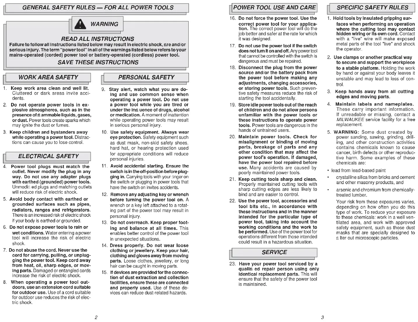
Failure to follow all Instructions listed below may result in electric shock, are and/or serious injury. The term "power tool" in all of the warnings listed below refers to your mains-operated (corded) power tool or battery-operated (cordless) power tool.
SAVE THESE INSTRUCTIONS
WORK AREA SAFETY
- Keep work area clean and well lit. Cluttered or dark areas invite accidents.
- Do not operate power tools in explosive atmospheres, such as in the presence of ammable liquids, gases, or dust. Power tools create sparks which may ignite the dust or fumes.
- Keep children and bystanders away while operating a power tool. Distractions can cause you to lose control.
ELECTRICAL SAFETY
- Power tool plugs must match the outlet. Never modify the plug in any way. Do not use any adapter plugs with earthed (grounded) power tools. Unmodified plugs and matching outlets will reduce risk of electric shock.
- Avoid body contact with earthed or grounded surfaces such as pipes, radiators, ranges and refrigerators. There is an increased risk of electric shock if your body is earthed or grounded.
- Do not expose power tools to rain or wet conditions. Water entering a power tool will increase the risk of electric shock.
- Do not abuse the cord. Never use the cord for carrying, pulling, or unplugging the power tool. Keep cord away from heat, oil, sharp edges, or moving parts. Damaged or entangled cords increase the risk of electric shock.
- When operating a power tool outdoors, use an extension cord suitable for outdoor use. Use of a cord suitable for outdoor use reduces the risk of electric shock.
PERSONAL SAFETY
- Stay alert, watch what you are doing and use common sense when operating a power tool. Do not use a power tool while you are tired or under the influence of drugs, alcohol or medication. A moment of inattention while operating power tools may result in serious personal injury.
- Use safety equipment. Always wear eye protection. Safety equipment such as dust mask, non-skid safety shoes, hard hat, or hearing protection used for appropriate conditions will reduce personal injuries.
- Avoid accidental starting. Ensure the switch is in the off-position before plugging In. Carrying tools with your finger on the switch or plugging in power tools that have the switch on invites accidents.
- Remove any adjusting key or wrench before turning the power tool on. A wrench or a key left attached to a rotating part of the power tool may result in personal injury.
- Do not overreach. Keep proper footing and balance at all times. This enables better control of the power tool in unexpected situations.
- Dress properly. Do not wear loose clothing or jewellery. Keep your hair, clothing and gloves away from moving parts. Loose clothes, jewellery, or long hair can be caught in moving parts.
- If devices are provided for the connection of dust extraction and collection facilities, ensure these are connected and properly used. Use of these devices can reduce dust-related hazards.
POWER TOOL USE AND CARE
- Do not force the power tool. Use the correct power tool for your application. The correct power tool will do the job better and safer at the rate for which it was designed.
- Do not use the power tool if the switch does not turn it on and off. Any power tool that cannot be controlled with the switch is dangerous and must be repaired.
- Disconnect the plug from the power source and/or the battery pack from the power tool before making any adjustments, changing accessories, or storing power tools. Such preventive safety measures reduce the risk of starting the tool accidentally.
- Store idle power tools out of the reach of children and do not allow persons unfamiliar with the power tools or these instructions to operate power tools. Power tools are dangerous in the hands of untrained users.
- Maintain power tools. Check for misalignment or binding of moving parts, breakage of parts and any other condition that may affect the power tool's operation. If damaged, have the power tool repaired before use. Many accidents are caused by poorly maintained power tools.
- Keep cutting tools sharp and clean. Properly maintained cutting tools with sharp cutting edges are less likely to bind and are easier to control.
- Use the power tool, accessories and tool bits etc., in accordance with these instructions and in the manner intended for the particular type of power tool, taking into account the working conditions and the work to be performed. Use of the power tool for operations different from those intended could result in a hazardous situation.
SERVICE
- Have your power tool serviced by a qualified repair person using only identical replacement parts. This will ensure that the safety of the power tool is maintained.
SPECIFIC SAFETY RULES
- Hold tools by insulated gripping surfaces when performing an operation where the cutting tool may contact hidden wiring or its own cord. Contact with a "live" wire will make exposed metal parts of the tool "live" and shock the operator.
- Use clamps or another practical way to secure and support the workpiece to a stable platform. Holding the work by hand or against your body leaves it unstable and may lead to loss of control.
- Keep hands away from all cutting edges and moving parts.
- Maintain labels and nameplates. These carry important information. If unreadable or missing, contact a MILWAUKEE service facility for a free replacement.
- WARNING: Some dust created by power sanding, sawing, grinding, drilling, and other construction activities contains chemicals known to cause cancer, birth defects or other reproductive harm. Some examples of these chemicals are:
- lead from lead-based paint
• crystalline silica from bricks and cement and other masonry products, and
• arsenic and chromium from chemically-treated lumber.
Your risk from these exposures varies, depending on how often you do this type of work. To reduce your exposure to these chemicals: work in a well-ventilated area, and work with approved safety equipment, such as those dust masks that are specially designed to liter out microscopic particles.
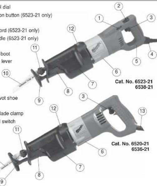
FUNCTIONAL DESCRIPTION
- Speed control dial
- Handle rotation button (6523-21 only)
- Trigger
- Quik-Lok ^® cord (6523-21 only)
- Rotating handle (6523-21 only)
- Nameplate
- Insulating boot
- Shoe release lever
Symbology
| Double Insulated | |
| C US | Underwriters Laboratories, Inc., United States and Canada |
| V~ | Volts Alternating Current |
| no xxxx/min. | No Load Strokes Per Minute (SPM) |
| A | Amps |
| ←→ | Straight Cut |
| Orbital Cut |
Specifications
| Cat. No. | Volts AC Only | Amps | Length of Stroke | Strokes per Minute |
| 6520-21 | 120 | 12 | 1-1/8" | 0 - 2800 |
| 6523-21 | 120 | 13 | 1-1/4" | 0 - 3000 |
| 6536-21 | 120 | 13 | 1-1/4" | 0 - 3000 |
| 6538-21 | 120 | 15 | 1-1/4" | 0 - 2800 |
GROUNDING

WARNING
Improperly connecting the grounding wire can result in the risk of electric shock. Check with a qualin ed electrician if you are in doubt as to whether the outlet is properly grounded. Do not modify the plug provided with the tool. Never remove the grounding prong from the plug. Do not use the tool if the cord or plug is damaged. If damaged, have it repaired by a MILWAUKEE service facility before use. If the plug will not at the outlet, have a proper outlet installed by a qualin ed electrician.
Grounded Tools:
Tools with Three Prong Plugs
Tools marked "Grounding Required" have a three wire cord and three prong grounding plug. The plug must be connected to a properly grounded outlet (See Figure A). If the tool should electrically malfunction or break down, grounding provides a low resistance path to carry electricity away from the user, reducing the risk of electric shock.
The grounding prong in the plug is connected through the green wire inside the cord to the grounding system in the tool. The green wire in the cord must be the only wire connected to the tool's grounding system and must never be attached to an electrically "live" terminal.
Your tool must be plugged into an appropriate outlet, properly installed and grounded in accordance with all codes and ordinances. The plug and outlet should look like those in Figure A.
Double Insulated Tools:
Tools with Two Prong Plugs
Tools marked "Double Insulated" do not require grounding. They have a special double insulation system which satisfies OSHA requirements and complies with the applicable standards of Underwriters Laboratories, Inc., the Canadian Standard Association and the National Electrical Code. Double Insulated tools may be used in either of the 120 volt outlets shown in Figures B and C.
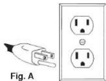
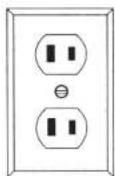
Fig. B
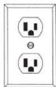
Fig. C
EXTENSION CORDS
Grounded tools require a three wire extension cord. Double insulated tools can use either a two or three wire extension cord. As the distance from the supply outlet increases, you must use a heavier gauge extension cord. Using extension cords with inadequately sized wire causes a serious drop in voltage, resulting in loss of power and possible tool damage. Refer to the table shown to determine the required minimum wire size.
The smaller the gauge number of the wire, the greater the capacity of the cord. For example, a 14 gauge cord can carry a higher current than a 16 gauge cord. When using more than one extension cord to make up the total length, be sure each cord contains at least the minimum wire size required. If you are using one extension cord for more than one tool, add the nameplate amperes and use the sum to determine the required minimum wire size.
Guidelines for Using Extension Cords
- If you are using an extension cord outdoors, be sure it is marked with the suffix "W-A" ("W" in Canada) to indicate that it is acceptable for outdoor use.
- Be sure your extension cord is properly wired and in good electrical condition. Always replace a damaged extension cord or have it repaired by a qualified person before using it.
- Protect your extension cords from sharp objects, excessive heat and damp or wet areas.
Recommended Minimum Wire Gauge for Extension Cords*
| Nameplate Amperes | Extension Cord Length | ||||
| 25' | 50' | 75' | 100' | 150' | |
| 0 - 2.0 | 18 | 18 | 18 | 18 | 16 |
| 2.1 - 3.4 | 18 | 18 | 18 | 16 | 14 |
| 3.5 - 5.0 | 18 | 18 | 16 | 14 | 12 |
| 5.1 - 7.0 | 18 | 16 | 14 | 12 | 12 |
| 7.1 - 12.0 | 16 | 14 | 12 | 10 | |
| 12.1 - 16.0 | 14 | 12 | 10 | ||
| 16.1 - 20.0 | 12 | 10 | |||
* Based on limiting the line voltage drop to five volts at 150% of the rated amperes.
READ AND SAVE ALL INSTRUCTIONS FOR FUTURE USE.
TOOL ASSEMBLY

WARNING
To reduce the risk of injury, always unplug tool before attaching or removing accessories or making adjustments. Use only specifically recommended accessories. Others may be hazardous.
Removing and Replacing Quik-Lok® Cords (Cat. No. 6523-21)
MILWAUKEE's exclusive Quik-Lok ^6 Cords provide instant 5 eld replacement or substitution.
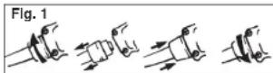
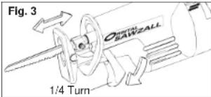
- To remove the Quik-Lok® Cord, turn the cord nut 1/4 turn to the left and pull it out.
- To replace the Quik-Lok® Cord, align the connector keyways and push the connector in as far as it will go. Turn the cord nut 1/4 tum to the right to lock.
Selecting a Blade
Use MILWAUKEE Sawzall® Blades for best performance. When selecting a blade, choose the right type and length.
Many types of blades are available for a variety of applications: cutting metal, wood, nail-embedded wood, scroll cutting, roughing-in, and contours.
Many lengths are also available. Choose a length long enough to extend beyond the shoe and your work throughout the stroke. Do not use blades less than 3-1/2" long since they won't extend beyond the shoe throughout the stroke.
For best performance and longest life, see "Accessories" to select the best blade for the job.
Quik-Lok® Blade Clamp
Unplug the tool before changing blades. Be sure the spindle and blade clamp areas are clean. Metal chips and sawdust may prevent the Quik-Lok® Blade Clamp from clamping securely.
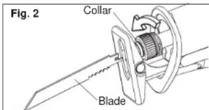
- Depending on the job, the blade may be inserted with the teeth facing up or down. To install a blade, twist collar in the direction of the arrow while inserting the blade into the clamp until the tang butts against the collar.
- Release collar and the spring loaded mechanism will clamp the blade firmly in place.
- Twist collar in the opposite direction of the arrow to ensure that the blade is locked into the clamp.
- Tug on blade to make sure it is securely locked in place.
- To remove a blade, twist collar in the direction of the arrow while pulling on the blade. Be careful when handling hot blades.
Quik-Lok® Blade Clamp Maintenance
- Periodically clean dust and debris from the Quik-Lok® Blade Clamp with dry compressed air.
- If the collar resists twisting, twist itr back and forth to shake debris loose.
- Periodically lubricate Quik-Lok® Blade Clamp with dry lubricant such as graphite.
Removing broken blades from the Quik-Lok® Blade Clamp
Unplug the tool before removing blades. Broken blades can be removed by the following methods.
- Point the tool downward, twist the collar, and shake the tool up and down (do not turn the tool on while your fingers are holding the blade clamp open). The shank of the broken blade should drop out of the clamp.
- If shaking the tool doesn't work: In most cases, a corner of the broken blade will extend beyond the blade clamp. Simply twist the collar and pull the broken blade out of the clamp by this corner.
- If the broken stub doesn't extend far enough to be grabbed by its corner, use a thin blade with small teeth (such as a metal cutting blade) to hook the blade that is jammed in the clamp while twisting the collar and pull it out.
OPERATION
WARNING
To reduce the risk of injury, wear safety goggles or glasses with side shields.
Adjustable Pivot Shoe
The shoe can be adjusted forward or backward to six positions to take advantage of the unused portion of the blade or for special jobs requiring low blade clearance.
- To adjust the shoe, pull the shoe release lever down 1/4 turn and slide the shoe forward or backward to the desired position.
- To lock the shoe in position, push the shoe release lever up.
- After adjusting the shoe, slowly pull the trigger to be sure the blade always extends beyond the shoe and your work throughout the stroke.
DO NOT OPERATE SAWZALL WITHOUT SHOE. STRIKING THE SPINDLE AGAINST WORK MAY DAMAGE THE RECIPROCATING MECHANISM.
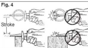
WARNING
To reduce the risk of injury, be sure the blade always extends beyond the shoe and work throughout the stroke. Blades may shatter if they impact the work or shoe (Fig. 4).
Impact Protection System
All models are equipped with a unique patented gearing system that provides efficient power transmission and extended life in the most difficult cutting applications. This durable system will absorb impacts, blade lock ups, and motor stalls. These models can be used for extreme cutting applications such as large diameter pipe, thick metal, pallets, and heavy demolition and renovation work as well as for general purpose cutting.
WARNING
Do not operate the Sawzall with the handle rotation button pressed in or with the handle not locked into position.
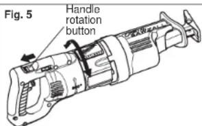
Rotating the Handle (Cat. No. 6523-21)
The 6523-21 Orbital Sawzall® handle can rotate continuously in either direction, allowing the user to achieve optimal cutting positions and comfort. The handle can be locked into one of eight (8) detent positions, one at every 45^ angle.
To rotate the handle:
- Unplug the tool.
- Press in the handle rotation button.
- Rotate the handle to the desired position.
- Release the handle rotation button. This will lock the handle firmly into position.
NOTE: Make sure the handle does not rotate before using the tool.
WARNING
If the handle can not be locked into position, do not operate the Sawzall®. Return the Sawzall® to a Milwaukee service facility immediately for repair.
Starting, Stopping and Controlling Speed
- To start the tool, grasp the handle firmly and pull the trigger.
- To stop the tool, release the trigger. Allow the tool to come to a complete stop before removing the blade from a partial cut or laying the tool down.
Orbit Control Switch
The Orbital Sawzall ^® is equipped with an orbit control switch. The tool may be operated with straight reciprocating (non orbital) or orbital action. Straight reciprocating action should be used when a smooth cut is needed. Orbital action is recommended for fast, aggressive cutting. The optimal orbital action should be determined by the user for their specific cutting requirements.
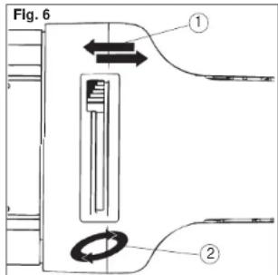
- For straight reciprocating action, move the orbit control switch to the straight cut symbol (1).
- For orbital action, move the orbit control switch towards the orbital cut symbol (2).
The amount of orbital action may be adjusted by moving the orbital control switch to any position between the two symbols. For larger orbital action, move the orbit control switch closer to the orbital cut symbol (2). For smaller orbital action, move the orbit control switch closer to the straight cut symbol (1).
Orbital action may be adjusted when the tool is running.
NOTE: Orbital action will not operate if the blade is installed upside down.
Selecting the Speed Range
The speed control dial controls the maximum strokes per minute. The speed will remain variable to the chosen dial setting by use of the trigger switch. Refer to the chart for recommended dial settings.
| MATERIAL | SUGGESTED DIAL SETTINGS* |
| Mild Steel | 2-3 |
| Wood | 5 |
| Nail-Embedded Wood | 5 |
| Stainless Steel | 1-3 |
| Drywall | 4-5 |
| Fiberglass | 1-3 |
| Plastics | 1-3 |
| Cast Iron | 2-3 |
| Non-Ferrous Metals | 2-3 |
* These are only suggested settings; the actual optimal setting may vary depending on line voltage, blade selected and user preference.
Trigger Speed Control Switch
These Sawzalls ^® are equipped with a trigger speed control switch. It may be operated at any speed from zero strokes per minute to full speed. Always start tool before blade contacts the workpiece. To vary the speed, simply increase or decrease the pressure on the trigger. The further the trigger is pulled, the greater the speed. To stop the tool, release the trigger and allow the tool to stop completely before removing from a partial cut or before laying the tool down.
General Cutting
For straight or contour cutting from an edge, line the blade up with your cutting line. Before the blade contacts the workpiece, grasp the handle a rmly and pull the trigger. Then guide the tool along your cutting line. Always hold the shoe a at against the workpiece to avoid excessive vibration.
Cutting Metals
Begin cutting at a slow speed, gradually increasing speed as you cut. When cutting into metals or hard materials that can not be cut from an edge, drill a starting hole larger than the widest part of the blade. Extend blade life by using a solid blade cutting lubricant.

To reduce the risk of explosion, electric shock and property damage, always check the work area for hidden gas pipes, electrical wires or water pipes when making blind or plunge cuts.
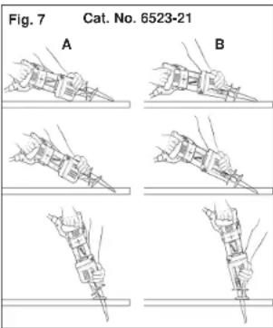
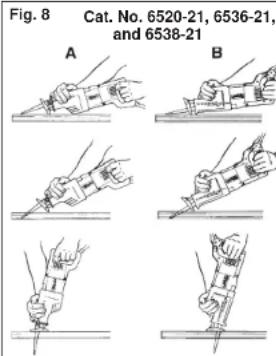
Plunge Cutting
Your MILWAUKEE Sawzall ^9 is ideal for plunge cutting directly into surfaces that can not be cut from an edge, such as walls or u oors. Orbital action is recommended for plunge cutting. Plunge cutting may be done two ways depending on how the blade is inserted. Column A shows how to plunge cut with the teeth of the blade facing down. Column B shows how to plunge cut with the teeth of the blade facing up.
NOTE: Orbital action will not operate if the blade is installed upside down.
Do not plunge cut into metal surfaces (see "Cutting Metals").
- Insert the blade into the tool.
If you inserted the blade with the teeth facing downward, hold the tool as shown in Column A, resting the edge of the shoe on the workpiece.
If you inserted the blade with the teeth facing upward, hold the tool as shown in Column B, resting the edge of the shoe on the workpiece as shown. -
With the blade just above the workpiece, pull the trigger. Using the edge of the shoe as a pivot, lower the blade into the workpiece as shown.
-
As the blade starts cutting, raise the handle of the tool slowly until the shoe rests firmly on the workpiece. Then guide the tool along your cutting line to acquire the desired cut.
NOTE: To make plunge cutting easier, use a heavy gauge blade and install the blade with the teeth facing upward as shown in Column B.
ACCESSORIES

To reduce the risk of injury, always unplug the tool before attaching or removing accessories. Use only speci cally recommended accessories. Others may be hazardous.
For a complete listing of accessories refer to your MILWAUKEE Electric Tool catalog or go on-line to www.milwaukeetool.com. To obtain a catalog, contact your local distributor or a service center.
Quik-Lok ^® Cord Sets
10' Quik-Lok® Cord Cat. No. 48-76-5010 25' Quik-Lok® Cord Cat. No. 48-76-5025
Carrying Case
Cat. No. 48-55-2055
Orbital Pipe Clamp System
Cat. No. 49-22-1016
Keyed Blade Clamp Kit
Cat. No. 49-22-5016
See Pages 38 & 39 for a listing of Sawzall ^® Blades.
MAINTENANCE

WARNING
To reduce the risk of injury, always unplug your tool before performing any maintenance. Never disassemble the tool or try to do any rewiring on the tool's electrical system. Contact a MILWAUKEE service facility for ALL repairs.
Maintaining Tools
Keep your tool in good repair by adopting a regular maintenance program. Before use, examine the general condition of your tool. Inspect guards, switches, tool cord set and extension cord for damage. Check for loose screws, misalignment, binding of moving parts, improper mounting, broken parts and any other condition that may affect its safe operation. If abnormal noise or vibration occurs, turn the tool off immediately and have the problem corrected before further use. Do not use a damaged tool. Tag damaged tools "DO NOT USE" until repaired (see "Repairs").
Under normal conditions, relubrication is not necessary until the motor brushes need to be replaced. After six months to one year, depending on use, return your tool to the nearest MILWAUKEE service facility for the following:
- Lubrication
• Brush inspection and replacement - Mechanical inspection and cleaning (gears, spindles, bearings, housing, etc.)
• Electrical inspection (switch, cord, armature, etc.) - Testing to assure proper mechanical and electrical operation

WARNING
To reduce the risk of injury, electric shock and damage to the tool, never immerse your tool in liquid or allow a liquid to flow inside the tool.
Cleaning
Clean dust and debris from vents. Keep the tool handles clean, dry and free of oil or grease. Use only mild soap and a damp cloth to clean your tool since certain cleaning agents and solvents are harmful to plastics and other insulated parts. Some of these include: gasoline, turpentine, lacquer thinner, paint thinner, chlorinated cleaning solvents, ammonia and household detergents containing ammonia. Never use a ammable or combustible solvents around tools.
Repairs
If your tool is damaged, return the entire tool to the nearest service center.
FIVE YEAR TOOL LIMITED WARRANTY
Every MILWAUKEE power tool (including cordless product – tool, battery pack(s) and battery charger and Work Lights – cordless ashlights) is warranted to the original purchaser only to be free from defects in material and workmanship. Subject to certain exceptions, MILWAUKEE will repair or replace any part on an electric power tool which, after examination, is determined by MILWAUKEE to be defective in material or workmanship for a period of live (5) years' after the date of purchase. Return the electric power tool and a copy of proof of purchase to a MILWAUKEE factory Service Center location or MILWAUKEE Authorized Service Station, freight prepaid and insured. This warranty does not apply to damage that MILWAUKEE determines to be from repairs made or attempted by anyone other than MILWAUKEE authorized personnel, misuse, alterations, abuse, normal wear and tear, lack of maintenance, or accidents.
*Every MILWAUKEE V™-technology (V18™ & V28™) LITHIUM-ION Battery Pack and M18 XC LITHIUM-ION Battery Pack is warranted for live (5) years / 2000 charges from the date of purchase, whichever first occurs. The first 1000 charges or 2 years of the warranty, whichever first occurs, are covered through free replacement of the defective battery. This means that for the earlier of the first 1000 charges or two (2) years from the date of purchase/first charge, a replacement battery will be provided to the customer for any defective battery free of charge. Thereafter, the remaining charges up to a total of 2000 or the remainder of the live (5) year period from the date of purchase, whichever first occurs, will be covered on a pro rata basis. This means that every customer gets an additional 1000 charges or three (3) years of pro rata warranty on the V™-technology LITHIUM-ION Battery Pack and M18 XC LITHIUM-ION Battery Pack depending upon the amount of use.
*The warranty period for ALL other LITHIUM-ION Battery Packs is two (2) years from the date of purchase.
*The warranty period for M12 2-Beam Laser & M12 Power Port, Ni-CD Battery Packs, Job Site Radios, and Trade Titan™ Industrial Work Carts is one (1) year from the date of purchase. Warranty Registration is not necessary to obtain the applicable warranty on a MILWAUKEE product. The manufacturing date of the product will be used to determine the warranty period if no proof of purchase is provided at the time warranty service is requested.
ACCEPTANCE OF THE EXCLUSIVE REPAIR AND REPLACEMENT REMEDIES DESCRIBED HEREIN IS A CONDITION OF THE CONTRACT FOR THE PURCHASE OF EVERY MILWAUKEE PRODUCT. IF YOU DO NOT AGREE TO THIS CONDITION, YOU SHOULD NOT PURCHASE THE PRODUCT. IN NO EVENT SHALL MILWAUKEE BE LIABLE FOR ANY INCIDENTAL, SPECIAL, CONSEQUENTIAL OR PUNITIVE DAMAGES, OR FOR ANY COSTS, ATTORNEY FEES, EXPENSES, LOSSES OR DELAYS ALLEGED TO BE AS A CONSEQUENCE OF ANY DAMAGE TO, FAILURE OF, OR DEFECT IN ANY PRODUCT INCLUDING, BUT NOT LIMITED TO, ANY CLAIMS FOR LOSS OF PROFITS. THIS WARRANTY IS EXCLUSIVE AND IN LIEU OF ALL OTHER WARRANTIES OR CONDITIONS, WRITTEN OR ORAL, EXPRESSED OR IMPLIED. WITHOUT LIMITING THE GENERALITY OF THE FOREGOING, MILWAUKEE DISCLAIMS ANY IMPLIED WARRANTY OF MERCHANTABILITY OR FITNESS FOR A PARTICULAR USE OR PURPOSE, AND ALL OTHER WARRANTIES.
This warranty applies to product sold in the U.S.A., Canada and Mexico only. Please consult the 'Service Center Search' in the Parts & Service section of MILWAUKEE's website www.milwaukeetool.com or call 1.800.SAWDUST (1.800.729.3878) to locate your nearest service facility for warranty and non-warranty service on a Milwaukee electric power tool.
RÈGLES GÉNÉRALES DE SÉCURITÉ POUR LES OUTILS ÉLECTRIQUE

AVERTISSEMENT
LIRE SOIGNEUSEMENT TOUTES LES INSTRUCTIONS
All blades have 1/2" universal tang.
UNITED STATES - MILWAUKEE Service
MILWAUKEE prides itself in producing a premium quality product that is NOTHING BUT HEAVY DUTY®.
Your satisfaction with our products is very important to us! If you encounter any problems with the operation of this tool, or you would like to locate the factory Service/Sales Support Branch or authorized service station nearest you, please call...
1-800-SAWDUST
(1.800.729.3878)
Monday-Friday
7:00 AM - 6:30 PM
Central Time
or visit our website at
www.milwaukeeetool.com
For service information, use the 'Service Center Search' icon found in the 'Parts & Service' section.
Additionally, we have a nationwide network of authorized Distributors ready to assist you with your tool and accessory needs. Check your "Yellow Pages" phone directory under "Tools-Electric" for the names & addresses of those nearest you or see the 'Where To Buy' section of our website.
Contact our Corporate After Sales Service Technical Support about ...
•Technical Questions
•Service/Repair Questions
•Warranty
call: 1-800-SAWDUST
fax: 1.800.638.9582
email: metproductsupport@milwaukeeetool.com
Register your tool online at
www.milwaukeetool.com and..
• receive important notifications regarding your purchase
- ensure that your tool is protected under the warranty
• become a HEAVY DUTY club member
Canada - Service MILWAUKEE
Milwaukee Electric Tool (Canada) Ltd
755 Progress Avenue
Scarborough, Ontario M1H 2W7
Dr. Andrade 140 Local B, Col. Doctores
MILWAUKEE ELECTRIC TOOL CORPORATION
13135 West Lisbon Road • Brookeld, Wisconsin, U.S.A. 53005
58-14-4050d5
09/09
Printed in USA


- SAVE THESE INSTRUCTIONS
- WORK AREA SAFETY
- ELECTRICAL SAFETY
- PERSONAL SAFETY
- POWER TOOL USE AND CARE
- SERVICE
- SPECIFIC SAFETY RULES
- FUNCTIONAL DESCRIPTION
- GROUNDING
- WARNING
- Grounded Tools:
- Tools with Three Prong Plugs
- Double Insulated Tools:
- Tools with Two Prong Plugs
- EXTENSION CORDS
- Guidelines for Using Extension Cords
- READ AND SAVE ALL INSTRUCTIONS FOR FUTURE USE.
- TOOL ASSEMBLY
- Removing and Replacing Quik-Lok® Cords (Cat. No. 6523-21)
- Selecting a Blade
- Quik-Lok® Blade Clamp Maintenance
- Removing broken blades from the Quik-Lok® Blade Clamp
- OPERATION
- Adjustable Pivot Shoe
- Impact Protection System
- Rotating the Handle (Cat. No. 6523-21)
- Starting, Stopping and Controlling Speed
- Orbit Control Switch
- Selecting the Speed Range
- Trigger Speed Control Switch
- General Cutting
- Cutting Metals
- Plunge Cutting
- ACCESSORIES
- Quik-Lok ® Cord Sets
- Carrying Case
- Orbital Pipe Clamp System
- Keyed Blade Clamp Kit
- MAINTENANCE
- Maintaining Tools
- Cleaning
- Repairs
- FIVE YEAR TOOL LIMITED WARRANTY
- RÈGLES GÉNÉRALES DE SÉCURITÉ POUR LES OUTILS ÉLECTRIQUE
- AVERTISSEMENT
- LIRE SOIGNEUSEMENT TOUTES LES INSTRUCTIONS
- UNITED STATES - MILWAUKEE Service
- 1-800-SAWDUST
- Register your tool online at
- www.milwaukeetool.com and..
- Canada - Service MILWAUKEE
- Milwaukee Electric Tool (Canada) Ltd
- MILWAUKEE ELECTRIC TOOL CORPORATION
- West Lisbon Road • Brookeld, Wisconsin, U.S.A. 53005
Brand : MILWAUKEE
Model : 652321
Category : Electric saw